Table of Contents
Advertisement
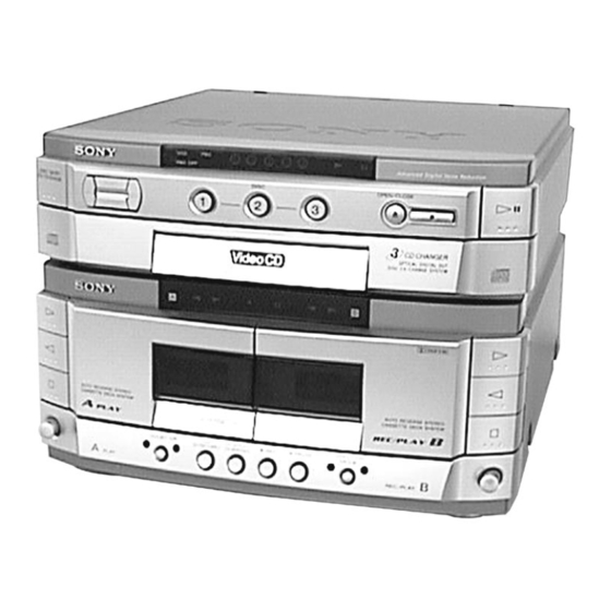
SERVICE MANUAL
• This set is the deck and Video CD
section in MHC-VX500/VX700AV.
This stereo system is equipped with the Dolby B-
type noise reduction system.
* Manufactured under license from Dolby
Laboratories Licensing Corporation.
DOLBY, the double-D symbol ; and "PRO LOGIC"
are trademarks of Dolby Laboratories Licensing
Corporation.
Video section
Inputs
Outputs
VIDEO CD/CD player section
System
Laser
Laser output
Frequency response
Wavelength
MICROFILM
SPECIFICATIONS
AV INPUT VIDEO (phono jack):
1Vp-p, 75 Ω
VIDEO IN (phono jack)
1Vp-p, 75 Ω
MONITOR OUT (phono jack):
1Vp-p, 75 Ω
VIDEO OUT (phono jack)
1Vp-p, 75 Ω
S-VIDEO (4-pin/mini-DIN jack):
Y: 1Vp-p, unbalanced, sync negative
C: 0.286Vp-p, load impedance 75 Ω
Compact disc, digital audio and video
system
Semiconductor laser (λ=780nm)
Emission duradon: continuous
Max. 44.6µW*
*This output is the value measured at a
diatance of 200 mm from the objective
lens surface on the Optical Pick-up Block
with 7 mm aperture.
20 Hz – 20 kHz (±1 dB)
780 – 790 nm
HTC-VX500
Model Name Using Similar Mechanism
CD
CD Mechanism Type
Section
Base Unit Type
Optical Pick-up Name
Model Name Using Similar Mechanism
Tape deck
Section
Tape Transport Mechanism Type
Signal to noise ratio
Dynamic range
Video Color System format
CD OPTICAL DIGITAL OUT
(Square optical connector jack, rear panel)
Wavelength
Output Level
Tape player section
Recording system
Frequency response
(DOLBY NR OFF)
General
Dimensions (w/h/d)
Mass
Design and specifications are subject to change without notice.
COMPACT DISC DECK
E Model
HTC-V5550
CDM38-5BD24
BU-5BD24
KSS-213BA/F-NP
HTC-V5550
TCM-230AWR2
TCM-230PWR2
More than 90 dB
More than 90 dB
NTSC, PAL
600 nm
–18 dBm
4-track 2-channel stereo
40 – 13,000 Hz (±3 dB),
using Sony TYPE
cassette
40 – 14,000 Hz (±3 dB),
using Sony TYPE
cassette
Approx. 288 × 205 × 360 mm
Approx. 4.6 kg
Advertisement
Chapters
Table of Contents

Subscribe to Our Youtube Channel
Related Manuals for Sony HTC-VX500


Summary of Contents for Sony HTC-VX500
- Page 1 Recording system 4-track 2-channel stereo Frequency response 40 – 13,000 Hz (±3 dB), VIDEO CD/CD player section (DOLBY NR OFF) using Sony TYPE cassette System Compact disc, digital audio and video 40 – 14,000 Hz (±3 dB), system using Sony TYPE Laser Semiconductor laser (λ=780nm)
- Page 2 COMPONENTS IDENTIFIED BY MARK ! OR DOTTED LINE WITH MARK ! ON THE SCHEMATIC DIAGRAMS AND IN THE PARTS LIST ARE CRITICAL TO SAFE OPERATION. REPLACE THESE COMPONENTS WITH SONY PARTS WHOSE PART NUMBERS APPEAR AS SHOWN IN THIS MANUAL OR IN SUPPLEMENTS PUBLISHED BY SONY.
-
Page 3: Table Of Contents
TABLE OF CONTENTS SERVICING NOTE ····················································· 4 GENERAL ····································································· 7 DISASSEMBLY 3-1. Loading Panel ····································································· 8 3-2. Back Panel and CD Mechanism Deck ······························· 8 3-3. Front Panel ········································································· 9 3-4. TC Mechanism Deck and Cassette Holder ························· 9 3-5. Disk Tray ········································································· 10 MECHANICAL ADJUSTMENTS ··························... -
Page 4: Servicing Note
SECTION 1 SERVICING NOTE HOW TO OPEN THE DISC TRAY WHEN POWER SWITCH TURNS OFF 1 Remove the Case. 3 Pull-out the disc tray. 2 Turn the cam to the direction of arrow. Note for Installation (ROTARY ENCODER) Note:When attaching the Base unit, Insert the BU cam section A into the groove of BU cam. - Page 5 Connection and Operations of the Unit by Itself This unit cannot be operated by itself as it does not come with a power supply. Connect STR-VX500/VX700 as shown in “Connection 1” before beginning servicing. Connection 1: If there is STR-VX500/VX700. STR-VX500/VX700 SYSTEM CABLE 17P AC IN...
- Page 6 Cold Reset NOTE: This is the mode for operating the unit by itself. Take note that the operating method differs when connected to the STR-VX500/ VX700. This method is described in the manuals of the STR-VX500 and STR-VX700. Refer to these manuals for details. This mode is used for initializing the RAM contents.
-
Page 7: General
SECTION 2 GENERAL Front Panel 2 3 4 qa qs qd qf Location of Parts and Controls 1 DISC SKIP/EX-CHANGE button w; DIRECTION MODE button 2 DISC 1 button wa X PAUSE button 3 DISC 2 button ws z REC button 4 DISC 3 button wd HI-SPEED DUBBING button 5 DISC NUMBER 1<... -
Page 8: Disassembly
SECTION 3 DISASSEMBLY Note: Follow the disassembly procedure in the numerical order given. 3-1. LOADING PANEL 3 Loading panel (Remove two claws) Two claws 2 Pull-out the disc tray. 1 Turn the cam to the direction of arrow. 3-2. BACK PANEL AND CD MECHANISM DECK qf CD mechanism deck 7 Back panel 4 Two screws... -
Page 9: Front Panel
3-3. FRONT PANEL 2 Flat type wire 1 Flat type wire (17core, CNS104) (17core, CNS102) 3 Flat type wire (15core, CNS101) 4 Connector (CN113) 6 Lead (with connector) 8 Front panel (Remove the catcher) Catcher 7 Connector (CNP105) 5 Two screws ×... -
Page 10: Disk Tray
3-5. DISC TRAY Note: When installing the Disc tray, pull around the flat type wire to pass through the claw A and claw B , as shown in the figure. 3 Flat type wire (8 core) 4 Two claws 2 Pull-out the disc tray. 5 Remove the disc tray. -
Page 11: Mechanical Adjustments
SECTION 4 SECTION 5 MECHANICAL ADJUSTMENTS ELECTRICAL ADJUSTMENTS Precaution Read before adjustments Clean the following parts with a denatured alcohol-moistened To adjust the unit, operate the unit by itself using the conduction jig swab: (PFJ-1). record/playback heads pinch rollers erase head rubber belts For details on switching functions and fast forwarding the unit, etc. - Page 12 Turn the adjustment screw and check output peaks. If the peaks Tape Speed Adjustment (Deck B) do not match for L-CH and R-CH, turn the adjustment screw so that outputs match within 1 dB of peak. Note: Set the test mode using the following method and begin tape speed adjustment.
- Page 13 Record Bias Adjustment (Deck B) Record Level Adjustment (Deck B) Procedure: Procedure: Press the x (CD) button while pressing the DIRECTION Press the x (CD) button while pressing the DIRECTION MODE button. MODE button. While pressing the x (CD) button, press the h (TAPE A) While pressing the x (CD) button, press the h (TAPE A) button, set the function to “deck B”.
- Page 14 RF signal waveform CD SECTION Notes: VOLT/DIV: 200 mV TIME/DIV: 500 ns 1. CD block basically constructed to operate without adjustment. There- (with the 10: 1 probe fore, check each item in order given. in use) 2. Use YEDS-18 disc (Part No.: 3-702-101-01) unless otherwise indicated. 3.
-
Page 15: Diagrams
HTC-VX500 SECTION 6 DIAGRAMS 6-1. CIRCUIT BOARDS LOCATION VIDEO SECTION Frequency Adjustment Connection: frequency counter VIDEO board VIDEO board REG board TP508 (27 MHz) – CD PANEL board VIDEO IN/OUT board Procedure: Connect the frequency counter to TP508 (27 MHz) on VIDEO board. -
Page 16: Block Diagrams
HTC-VX500 6-2. BLOCK DIAGRAMS SERVO SECTION MCLK IC104 33.8MHz (Page 17) FILTER RF AMP, FOCUS/TRACKING ERROR AMP IC103 DETECTOR A+5V XTSL CTL1 CLOCK DIGITAL SIGNAL PROCESSOR GENERATOR IC101 (1/2)(BD BOARD) DATA, BCK, LRCK, C2PO DATA DATA (Page 17) DIGITAL PLL... -
Page 17: Audio/Video Cd Section
HTC-VX500 AUDIO/VIDEO CD SECTION (Page 16) DIGITAL FILTER, D/A CONVERTER IC509 (Page 19) MPEG VIDEO/AUDIO DECODER, DIGITAL DATA CD-L DA-DATA VOUTL VIDEO SIGNAL PROCESSOR MPEG LOW-PASS AUDIO INPUT FILTER, DA-BCK LOW-PASS IC505 AUDIO INTERFACE INTERFACE NOISE FILTER CONVERTER FILTER DA-LRCK... -
Page 18: Tape Deck Section
HTC-VX500 TAPE DECK SECTION DECK PROCESS DECK A/B SELECT, PB/REC EQ AMP, DOLBY NR AMP, ALC, AMS • SIGNAL PATH IC301 : PB (DECK A) HP101 DOLBY PASS (PLAYBACK) : PB (DECK B) PB OUT (L) PB-L PB EQ AMP... -
Page 19: Power Section
HTC-VX500 POWER SECTION M12V THIS NOTE IS COMMON FOR PRINTED WIRING BOARDS AND SCHEMATIC DIAGRAMS. +7.5V REG +12V REG A+7.5V IC851 (In addition to this, the necessary note is printed Q852 in each block.) For schematic diagrams. Note: +5V REG •... -
Page 20: Printed Wiring Board Cd Section
HTC-VX500 6-3. PRINTED WIRING BOARD CD SECTION • Refer to page 15 for Circuit Boards Location. BA F (Page 32) • Semiconductor Location Ref. No. Location IC101 IC102 C-10 IC103 IC104 Q101 E-12 Q102 Q103... -
Page 21: Schematic Diagram Cd Section
HTC-VX500 6-4. SCHEMATIC DIAGRAM CD SECTION • Refer to page 35 for Waveforms. • Refer to page 38, 39 for IC Block Diagrams. (Page 33) The components identified by mark ! or dotted line with mark ! are critical for safety. -
Page 22: Schematic Diagram Deck Section
HTC-VX500 6-5. SCHEMATIC DIAGRAM DECK SECTION • Refer to page 39 for IC Block Diagrams. MAIN BOARD CNS101 (Page 25) The components identified by mark ! or dotted line with mark ! are critical for safety. Replace only with part number specified. -
Page 23: Printed Wiring Board Deck Section
HTC-VX500 6-6. PRINTED WIRING BOARD DECK SECTION • Refer to page 15 for Circuit Boards Location. MAIN BOARD CNS101 (Page 24) -
Page 24: Printed Wiring Board Main Section
HTC-VX500 6-7. PRINTED WIRING BOARD MAIN SECTION • Refer to page 15 for Circuit Boards Location. (Page 28) (Page 28) (Page 31) (Page 31) (Page 32) (Page 27) (Page 28) • Semiconductor Location (Page 23) Ref. No. Location D110 D855... -
Page 25: Schematic Diagram Main (1/2) Section
HTC-VX500 6-8. SCHEMATIC DIAGRAM MAIN (1/2) SECTION • Refer to page 39 for IC Block Diagrams. (Page 27) (Page 30) (Page 30) (Page 33) (Page 22) (Page 33) -
Page 26: Schematic Diagram Main (2/2) Section
HTC-VX500 6-9. SCHEMATIC DIAGRAM MAIN (2/2) SECTION • Refer to page 24 for Printed Wiring Board. • Refer to page 41 for IC Pin Function Description. (TH,IA) EPM7064-RCONT2-V1.0 (EA,HK,MY,SP) The components identified by mark ! or dotted (Page 29) line with mark ! are critical for safety. -
Page 27: Printed Wiring Board Leaf Sw Section
HTC-VX500 6-10. PRINTED WIRING BOARD LEAF SW SECTION • Refer to page 15 for Circuit Boards Location. MAIN BOARD CNS104 (Page 24) 6-11. SCHEMATIC DIAGRAM LEAF SW SECTION MAIN BOARD CNS104 (Page 25) -
Page 28: Printed Wiring Board Panel Section
HTC-VX500 6-12. PRINTED WIRING BOARD PANEL SECTION • Refer to page 15 for Circuit Boards Location. (Page 24) CD PANEL BOARD (Page 24) (Page 24) -
Page 29: Schematic Diagram Panel Section
HTC-VX500 6-13. SCHEMATIC DIAGRAM PANEL SECTION (Page 26) (Page 26) (Page 26) -
Page 30: Schematic Diagram Cd Motor Section
HTC-VX500 6-14. SCHEMATIC DIAGRAM CD MOTOR SECTION • Refer to page 39 for IC Block Diagrams. MAIN BOARD CN112 (Page 25) MAIN BOARD CN111 (Page 25) -
Page 31: Printed Wiring Board Cd Motor Section
HTC-VX500 6-15. PRINTED WIRING BOARD CD MOTOR SECTION • Refer to page 15 for Circuit Boards Location. MAIN BOARD CN112 (Page 24) MAIN BOARD CN111 (Page 24) -
Page 32: Printed Wiring Board Video Section
HTC-VX500 6-16. PRINTED WIRING BOARD VIDEO SECTION • Refer to page 15 for Circuit Boards Location. (Page 34) • Semiconductor • Semiconductor Location Location Ref. No. Location Ref. No. Location D301 IC501 D501 IC502 D502 IC506 IC101 Q302 IC401 Q303... -
Page 33: Schematic Diagram Video (1/2) Section
HTC-VX500 6-17. SCHEMATIC DIAGRAM VIDEO (1/2) SECTION • Refer to page 42 for IC Pin Function Description. • Refer to page 35 to 37 for Waveforms. (Page 21) (Page 25) (Page 25) -
Page 34: Schematic Diagram Video (2/2) Section
HTC-VX500 6-18. SCHEMATIC DIAGRAM VIDEO (2/2) SECTION • Refer to page 32 for Printed Wiring Board. • Refer to page 35 to 37 for Waveforms. • Refer to page 39 for IC Block Diagrams. • Refer to page 44 for IC Pin Function Description. - Page 35 • Waveforms VIDEO BOARD BD BOARD 1 IC501 5 (LRCK) 1 IC101 wh (RFDC) 200 mV/DIV, 500 ns/DIV 6 IC101 rj (BCLK) +0.25 Vp-p 5.2 Vp-p –0.20 5 Vp-p 22.8 µ s 474 ns 2 IC501 qd (BCLK) 2 IC101 wj (TE) 200 mV/DIV, 100 µs/DIV 7 IC101 ys (XTAI) 4.4 Vp-p 5.2 Vp-p...
- Page 36 qh IC505 <zzz (DA-BCK), IC509 !¶ (BCK) 6 IC402 ql (XIN) qa IC505 ug (C-OUT) 4.8 Vp-p 3.4 Vp-p 0.5 Vp-p 8.1 MHz 472 ns 7 IC402 w; (XOUT) qs IC505 ih (DA-XCLK) qj Q301 (Base) 1.8 Vp-p 4.2 Vp-p 5.2 Vp-p 8.1 MHz 60 ns...
- Page 37 wa IC509 w; (384FSO) wh IC401 3 1 Vp-p 5.1 Vp-p 59 ns ws IC509 wa (768FSO) wj IC401 1 4.8 Vp-p 2 Vp-p 30 ns wd IC509 wf (XT2) wk J301 3 (COUT) 1 Vp-p 1 Vp-p 27 MHz wf IC401 7 wl J301 4 (YOUT) 1.7 Vp-p...
-
Page 38: Ic Block Diagrams
6-19. IC BLOCK DIAGRAMS • BD BOARD IC101 CXD2545Q SFDR RFDC SSTP FILO LOCK FILI CLTV AVSS RFAC BIAS DFCT MIRR ASYI COUT CLOK XLAT DATA ASYO AVDD ATSK DFSW SCLK ASYE DIRC XRST SENS MUTE SQCK PSSL SQSO WDCK LRCK DA16 EXCK... -
Page 39: Audio Board
IC103 CXA1821M-T6 • VIDEO IN/OUT BOARD IC601 NJM4580D-D A OUT LD ON A –IN B OUT LC/PD APC LD AMP VREF RF EQ AMP A +IN B –IN RF SUMMING AMP V– B +IN FOCUS ERROR AMP FE BIAS TRACKING ERROR AMP VC BUFFER •... -
Page 40: Ic Pin Function Description
6-20. IC PIN FUNCTION DESCRIPTION • MAIN BOARD IC101 MASTER CONTROL (uPD780016AYGF-022-3BA/EPM7064-RCONT2-V1.0) Pin No. Pin Name Description CAPM-EMG (+) Capstan motor control 1 (+) signal output 2 to 7 LED1 to LED6 — Not used — Ground X’tal (5MHz) — Power supply (+5V) —... - Page 41 Pin No. Pin Name Description TBL-L Table motor control output TBL-R — Not used LOAD-OUT Loading motor control signal output LOAD-IN CD-PAUSE DECO2 CD-PLAY LED ON/OFF control output EXIST3 EXIST1 DISC3 — Ground DISC1 LED ON/OFF control output SENSE2 BD Condition signal input SENS DISC-SENS Slit sensor of disc table input...
- Page 42 • VIDEO BOARD IC502 M30620MC-313FP (CD MECHANISM CONTROLLER) Pin No. Pin Name Description SENSE Internal status (SENSE) signal input from the CXD2545Q (IC101) SENSE CLK Sense serial data reading clock signal output to the CXD2545Q (IC101) DSP DATA Serial data output to the CXD2545Q (IC101) DSP LATCH Serial data latch pulse output to the CXD2545Q (IC101) DSP CLK...
- Page 43 Pin No. Pin Name Description — Not used (open) BUS XHOLD Hold signal input terminal Not used (fixed at “H”) 42,43 — Not used (open) SHIMUKE Destination setting terminal “L”: Chinese, “H”: English Vertical synchronized signal input from the MPEG video/audio decoder (IC505) “L” active BUS XWRL —...
- Page 44 • VIDEO BOARD IC505 CL680T-D1 (MPEG VIDEO/AUDIO DECODER, VIDEO SIGNAL PROCESSOR) Pin No. Pin Name Description — Not used (open) — Ground terminal CD-BCK CD decode bit clock signal (2.8224 MHz) input from the CXD2545Q (IC101) CD-DATA CD decode data input from the CXD2545Q (IC101) CD-LRCK CD decode L/R sampling clock signal (44.1 kHz) input from the CXD2545Q (IC101) CD-C2PO...
- Page 45 Pin No. Pin Name Description RREF Fix the video signal output level control VREF Reference voltage (+1.235V) output terminal AVDD-DAC — Power supply terminal (+3.3V) (for D/A converter) C-OUT Chrominance video signal output terminal AGND-DAC — Ground terminal (for D/A converter) CLK-SEL0 GCK (pin<z/b ) selection terminal “L”: external clock, “H”: internal clock (fixed at “H”) CLK-SEL1...
- Page 46 Pin No. Pin Name Description VDD3 — Power supply terminal (+3.3V) HSEL Command selection signal input from the CD mechanism controller (IC502) CDG-SDATA — Not used (fixed at “L”) CDG-VFSY — Not used (fixed at “L”) CDG-S0S1 — Not used (fixed at “L”) 125 to 128 —...
-
Page 47: Exploded Views
SECTION 7 EXPLODED VIEWS NOTE: • -XX, -X mean standardized parts, so they may • The mechanical parts with no reference number The components identified by mark ! or have some differences from the original one. in the exploded views are not supplied. dotted line with mark ! are critical for safety. -
Page 48: Front Panel Section
* 65 1-669-422-11 TC(A) BOARD X-4951-674-1 ESCUTHEON (TC) ASSY 4-215-062-01 DAMPER X-4951-772-1 ESCUTCHEON CD ASSY 3-019-456-11 SCREW, STEP 4-962-708-11 EMBLEM (4-A), SONY 4-900-888-01 EJECT (LEVER-L) 4-900-881-11 BUTTON (EJECT A) 4-900-889-01 EJECT (LEVER-R) 4-900-882-11 BUTTON (EJECT-B) * 71 1-669-420-11 CDPANEL BOARD... -
Page 49: Cd Mechanism Section 1 (Cdm38-5Bd24)
7-3. CD MECHANISM SECTION 1 (CDM38-5BD24) M701 Ref. No. Part No. Description Remarks Ref. No. Part No. Description Remarks 4-981-789-01 BRACKET (2), YOKE 4-977-941-01 BEARING (WORM) 4-977-945-01 TRAY (TURN) * 209 1-658-576-11 SENSOR BOARD X-4946-665-1 SHAFT ASSY, WORM 4-934-376-01 SHAFT (ROLLER) 4-977-943-01 BELT (TURN) (1.2) 4-981-187-01 COLLAR (WORM) 4-977-956-01 WHEEL, WORM... -
Page 50: Cd Mechanism Section 2 (Cdm38-5Bd24)
7-4. CD MECHANISM SECTION 2 (CDM38-5BD24) supplied M801 BU-5BD24 S811 Ref. No. Part No. Description Remarks Ref. No. Part No. Description Remarks 4-981-789-11 BRACKET (2), YOKE * 260 X-4946-668-1 CHASSIS (CDM) ASSY 4-977-954-01 PULLEY (SL) 4-985-672-01 SCREW (+PTPWHM2.6), FLOATING 4-977-953-01 GEAR (SL-A) * 262 1-658-578-11 MOTOR (SLIDE) BOARD 4-977-955-01 GEAR (SL-B) -
Page 51: Base Unit Section (Bu-5Bd24)
7-5. BASE UNIT SECTION (BU-5BD24) M101 M102 Ref. No. Part No. Description Remarks Ref. No. Part No. Description Remarks ! 301 8-848-379-31 OPTICAL PICK-UP BLOCK KSS-213BA/F-NP * 307 A-4699-697-A BD BOARD, COMPLETE 1-769-069-11 WIRE (FLAT TYPE) (16 CORE) 4-951-620-41 SCREW (2.6), +BVTP 3-713-786-51 SCREW +P 2 ×... -
Page 52: Tc Mechanism Section 1 (Tcm-230Awr2/230Pwr2)
7-6. TC MECHANISM SECTION 1 (TCM-230AWR2/230PWR2) * NOTE: Two types of parts which are not interchangeable are available for the Head deck (A) ASSY and Head deck (B) ASSY. When replacing the parts, refer to the following figure, and use the appropriate part Parts with “P”... -
Page 53: Tc Mechanism Section 2 (Tcm-230Awr2/230Pwr2)
7-7. TC MECHANISM SECTION 2 (TCM-230AWR2/230PWR2) * NOTE: Two types of parts which are not interchangeable are available for the mechanical block assembly. When replacing the parts, refer to the following figure, and use the appropriate part. Parts with “P” mark: 230PWR2 Parts without “P”... -
Page 54: Electrical Parts List
SECTION 8 AUDIO ELECTRICAL PARTS LIST NOTE: • Due to standardization, replacements in the • RESISTORS When indicating parts by reference number, parts list may be different from the parts All resistors are in ohms. please include the board name. specified in the diagrams or the components METAL: metal-film resistor used on the set. - Page 55 AUDIO Ref. No. Part No. Description Remarks Ref. No. Part No. Description Remarks R612 1-249-409-11 CARBON 1/4W F < CONNECTOR > ! R621 1-212-851-00 FUSIBLE 1/4W F ! R622 1-212-851-00 FUSIBLE 1/4W F CN101 1-770-706-11 CONNECTOR, FFC/FPC 23P R623 1-249-432-11 CARBON 1/4W CN102 1-777-937-11 CONNECTOR, FFC/FPC 16P...
- Page 56 CD PANEL CONNECTOR LEAF SW Ref. No. Part No. Description Remarks Ref. No. Part No. Description Remarks R173 1-216-025-91 RES,CHIP 1/10W R251 1-249-406-11 CARBON 1/4W F R175 1-216-025-91 RES,CHIP 1/10W R252 1-249-406-11 CARBON 1/4W F R176 1-216-073-00 METAL CHIP 1/10W R253 1-249-410-11 CARBON 1/4W F...
- Page 57 LEAF SW MAIN Ref. No. Part No. Description Remarks Ref. No. Part No. Description Remarks < CABLE > C137 1-164-159-11 CERAMIC 0.1uF C138 1-104-665-11 ELECT 100uF * DM1001 1-784-581-11 HOLDER, CABLE (2.5MM PITCH) 4P C139 1-128-551-11 ELECT 22uF C140 1-164-159-11 CERAMIC 0.1uF <...
- Page 58 Q343 8-729-029-66 TRANSISTOR DTC114ESA-TP R328 1-249-425-11 CARBON 4.7K 1/4W F Q852 8-729-018-60 TRANSISTOR 2SD2012-LC R329 1-249-437-11 CARBON 1/4W Q855 8-729-018-59 TRANSISTOR 2SB1375(LB-SONY) R330 1-249-425-11 CARBON 4.7K 1/4W F R331 1-249-437-11 CARBON 1/4W < RESISTOR > R332 1-249-415-11 CARBON 1/4W F...
- Page 59 MOTOR (SLIDE) MOTOR (TURN) SENSOR Ref. No. Part No. Description Remarks Ref. No. Part No. Description Remarks R337 1-249-417-11 CARBON 1/4W F < SWITCH > R338 1-249-411-11 CARBON 1/4W R339 1-249-437-11 CARBON 1/4W S801 1-762-527-11 SWITCH, ROTARY (OPEN/CLOSE) R340 1-249-437-11 CARBON 1/4W ************************************************************ R341...
-
Page 60: Tcpanel Board
SENSOR TC (A) TC (B) TC LED TC PANEL VIDEO Ref. No. Part No. Description Remarks Ref. No. Part No. Description Remarks < RESISTOR > < RESISTOR > R701 1-249-416-11 CARBON 1/4W F R221 1-249-406-11 CARBON 1/4W F R702 1-249-407-11 CARBON 1/4W F R222 1-249-406-11 CARBON... - Page 61 VIDEO Ref. No. Part No. Description Remarks Ref. No. Part No. Description Remarks C402 1-124-778-00 ELECT CHIP 22uF 6.3V < CONNECTOR > C403 1-124-778-00 ELECT CHIP 22uF 6.3V C404 1-126-206-11 ELECT CHIP 100uF 6.3V * CN301 1-564-506-11 PLUG, CONNECTOR 3P C405 1-110-530-11 ELECT CHIP 1000uF...
- Page 62 VIDEO Ref. No. Part No. Description Remarks Ref. No. Part No. Description Remarks < TRANSISTOR > R406 1-216-081-00 METAL CHIP 1/10W R407 1-216-073-00 METAL CHIP 1/10W Q301 8-729-024-91 TRANSISTOR 2SC2712-GL-TE85L R408 1-216-073-00 METAL CHIP 1/10W Q302 8-729-024-91 TRANSISTOR 2SC2712-GL-TE85L R409 1-216-049-91 RES,CHIP 1/10W Q303...
- Page 63 VIDEO VIDEO IN/OUT Ref. No. Part No. Description Remarks Ref. No. Part No. Description Remarks R545 1-216-025-91 RES,CHIP 1/10W < FERRITE BEAD > R546 1-216-049-91 RES,CHIP 1/10W R547 1-216-295-91 SHORT FB603 1-412-473-21 INDUCTOR R548 1-216-049-91 RES,CHIP 1/10W R549 1-216-025-91 RES,CHIP 1/10W <...
- Page 64 HTC-VX500 Sony Corporation 9-929-006-11 99H16091-1D Home Audio Company Printed in Japan ©1999.8 Published by Quality Assurance Dept.
Need help?
Do you have a question about the HTC-VX500 and is the answer not in the manual?
Questions and answers