
Related Manuals for Net Optics iBypass


Summary of Contents for Net Optics iBypass
-
Page 1: User Guide
User Guide iBypass Switches with Heartbeat ™ 800-0182-001 Doc. PUBIBPOHBU Rev. B 6/11... - Page 2 PLEASE READ THESE LEGAL NOTICES CAREFULLY. By using a Net Optics iBypass Switch you agree to the terms and conditions of usage set forth by Net Optics, Inc. No licenses, express or implied, are granted with respect to any of the technology described in this manual.
-
Page 3: Table Of Contents
Plan the Installation ..........9 Unpack and Inspect the iBypass Switch ....... . .10 Installing XFP or SFP Monitor Port Transceivers . - Page 4 Switch CLI Syntax ........
-
Page 5: Introduction
Heartbeat Packet The iBypass Switch monitors the attached device by sending a Heartbeat packet to the device. If the iBypass Switch does not receive the Heartbeat response, it automatically switches network traffic to bypass the unresponsive device—even if the device is still receiving power. The iBypass continues to send the Heartbeat, and will restore traffic flow through the device as soon as the link is restored .For... - Page 6 Bypass Detect You can set the Monitor Ports to cycle on and off while the iBypass Switch is in Bypass ON mode in order to trigger attached devices to alarms to a management system. In Bypass Detect mode, the monitor ports will cycle through five seconds off followed by fifteen seconds on.
-
Page 7: Bypass Modes
• Email: ts-support@netoptics.com • Customer Portal: http://customer.netoptics.com/portal Bypass Modes The iBypass Switch with Heartbeat bypasses attached in-line device and sends traffic straight through the network link when one of three events occurs: • Power loss to the switch • Link failure... - Page 8 Switches with Heartbeat Two LEDs on the front of the iBypass Switch indicate whether the switch is bypassing the connected appliance or not. When the Bypass ON indicator is illuminated, the iBypass Switch has not received the heartbeat packet as expected and directly connects Network Ports A and B.
-
Page 9: Tap Mode During Bypass
(for example, once every millisecond from Monitor Port 1). The iBypass Switch validates the path when it receives the packet on the Monitor Port 2. If the iBypass Switch does not receive the packet as expected three times in a row (assuming the Retry count is set to 3), the iBypass Switch automatically enters Bypass ON mode. -
Page 10: Snmp Traps
The iBypass Switch collects statistics about the traffic passing through each of its ports. The statistics can be viewed and cleared using any of the management interfaces. The traffic statistics collected by the iBypass Switch on each of its ports are: • Peak traffic rate • Time of the peak traffic •... -
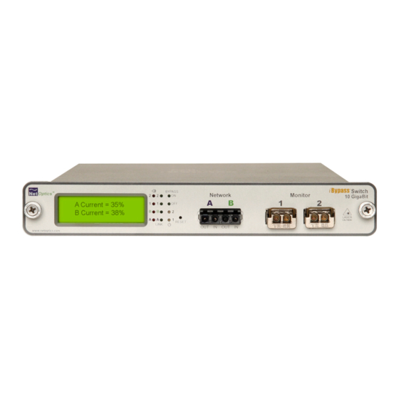
Page 11: Front Panel
The day and time information reflects the highest peak event since reset. You can set the iBypass Switch 24-hour clock through the CLI or by using the remote manager interfaces. -
Page 12: Threshold Alarm Leds
If there is no current activity on this link, the LED flashes. Power LEDs If the iBypass Switch is deployed with both power supplies, both power LEDs will illuminate when connected to power. If a power LED is off, the corresponding power supply is not functioning or connected. -
Page 13: Installing The Ibypass Switch
Plan the Installation Before you begin the installation of your iBypass Switch, determine the following: • IP address of the iBypass Switch or, if you are deploying multiple iBypass Switches, a range of IP addresses • Net Mask for the iBypass Switch •... -
Page 14: Unpack And Inspect The Ibypass Switch
• Quick Installation Guide • CD that contains this manual and System Manager software You may have also purchased a panel for rack mounting the iBypass Switch, and an extended warranty. If any component is missing or damaged, contact Net Optics Customer Service immediately at +1 (408) 737-7777. -
Page 15: Connect Power To The Ibypass Switch
Switches with Heartbeat 2. Slide the iBypass Switch into one of the slots and secure the device by tightening the thumb screws. 3. Make sure that the rack is properly grounded. Connect Power to the iBypass Switch For power fault protection, the iBypass Switch has redundant power supplies. The second power supply is available to support the flow of traffic to the monitoring device in the event that the first power supply becomes unavailable. -
Page 16: Connecting To The Cli Interface
Switch Command Line Interface. You will now set a new username and password, IP address for the iBypass Switch, utilization threshold levels for Port A and B, and the current date and time. Other parameters are optional and dependent on your installation. -
Page 17: Configure The Ibypass Switch With The Cli
Switches with Heartbeat 3. Power on the iBypass Switch. The Net Optics CLI banner and login prompt appear in the Terminal Emulation software (see below). The login default is netoptics. ************************************* * Net Optics Command Line Interface * *************************************... - Page 18 To change the iBypass Switch IP address: Enter set ip <new ip address>. Example: Enter set ip 10.60.10.100 to set the iBypass Switch IP address to 10.60.10.100. Web Manager and System Manager will connect to the device at this address.
- Page 19 Display and Check Current Settings Enter show set. The CLI displays the current setting, similar to the example below. Net Optics> show set show set Model: Net Optics Management System for HB Bypass System Time: 03/29/2011 18:25:14 IP Address: 10.60.4.20 Netmask: 255.0.0.0 Manager: 192.168.0.1...
- Page 20 Switches with Heartbeat Use the CLI Help Command 1. Enter Help at the Net Optics prompt. The list of help topics is displayed. Net Optics> help ************************************* * Net Optics Command Line Interface * ************************************* Usage: "help <variable>" display - Toggle internet accessibility and LCD display.
-
Page 21: Connect The Ibypass Switch To The Network
Switches with Heartbeat Do not disconnect the DB9 cable yet from the RS232 port. You will use it once more to turn the iBypass Switch display on and off. Connect the iBypass Switch to the Network To connect the iBypass Switch to the network: 1. -
Page 22: Connect A Monitoring Device To The Ibypass Switch
1. Enter show display to view the current setting. The default value is ON. 2. Enter display. Now look at the front of the iBypass Switch. Access from the Management Port is blocked and the iBypass Switch front panel does not display utilization or peak information. -
Page 23: Check The Installation
To Monitoring Device Figure 10: Connecting the Monitoring Devices Check the Installation You have connected the iBypass Switch to the network, to the monitoring device and to power. It should be functioning correctly now. Check the status of the fol- lowing: •... -
Page 24: Web Manager
Switch with an IP address. Web Manager supports all common browsers. To access Web Manager: 1. Open an Internet browser on your computer. 2. Enter the iBypass Switch IP address in the URL. The default IP address is 192.168.2.100. Web Manager displays, as shown in the following figure. - Page 25 Switches with Heartbeat Figure 11: Web Manager main screen...
- Page 26 Web Manager window. You cannot change the Status or Statistics fields; they are read-only. Field Name Description Bypass System Status System Status Status of the iBypass, UP or DOWN Link Status Status of the port Link, UP or DOWN Port Speed Speed for the port Power Supply...
- Page 27 Port B, Port 1, Port 2 (separate control for each port). The Peak Rate is a traffic measurement during peak time. The Net Optics iBypass Web Manager will capture the highest peak rate and time, and then display them in the Statistics section.
-
Page 28: Set Date And Time Window
Number of seconds (from 20 to 900) between automatic Interval reloads of the Web Manager page;. 4. Save changes to the iBypass Switch by clicking Submit Changes at the bottom of the page. 5. To update the display, click your browser's refresh button. -
Page 29: Check/Change The Heartbeat Packet From Web Manager
Check/Change the Heartbeat Packet from Web Manager Use the Heartbeat window to view hexadecimal information about the current Heartbeat packet or to edit the Net Optics Heartbeat packet and create your own customized Heartbeat packets (one for each monitored device). You can do this from Web Manager or System Manager. -
Page 30: Download And Install New Software
66 67 68 69 B8 8E 1C A9 Download and Install New Software Use the Software Download window to download and install new software into the iBypass Switch. You can find software release information in the Net Optics Customer Portal. - Page 31 6. Click Go Back to Main Menu to return to the main Web Manager window. Tips! ____________________________________________________________________ See the Technical Note Upgrading iTap and iBypass Software Using HFS for instructions for setting up a Web File Server for downloading software to the iBypass Switch.
-
Page 32: Set Port Parameters
3. Select Yes to enable link autonegotiation or No for fixed settings. 4. Select the link speed if it is a 10/100/1000 iBypass Switch, Gigabit for 1000 Mbps, 100 BT for 100 Mbps, or 10 BT for 10 Mbps. You must select Yes for one speed and No for the other two. -
Page 33: System Manager
System Manager Overview This chapter describes how to install and use the Net Optics System Manager. Use the System Manager to change system settings, to view system status, and retrieve data from configured Net Optics iBypass Switch devices. The following topics are covered: •... -
Page 34: Install System Manager
Switches with Heartbeat Install System Manager The executable installation file for System Manager is distributed on the CD in- cluded with the iBypass Switch. To install System Manger: 1. Locate Setup.exe on the CD and double click it. The License Agreement appears. -
Page 35: Explore System Manager
• View traffic utilization and peaks • View traffic statistics NOTE ___________________________________________________________________ In order to access an iBypass Switch with System Manager, the Display option must be set to ON in the CLI. For more information, see Using the Command Line Interface in Chapter 2. -
Page 36: Using The Toolbar
2. Log in with the default User Name netoptics and Password netoptics. The initial System Manager window appears. A new System Manager does not yet show any Net Optics units. The System Frame portion of the window (left side) displays iBypass Switches and Groups as you add them to the system. -
Page 37: Create A System Manager Group
View information about System Manager Create a System Manager Group Organize iBypass Switches or other Net Optics devices into groups for quick ac- cess. Devices must belong to a group. If you add an iiBypass Switch when there is no group, a group is created automatically. -
Page 38: Add Devices To A System Manager Group
3. Enter a name for the iBypass Switch in the Node Name text box. Each Node Name in the system must be unique. 4. Enter the IP address of the iBypass Switch in the IP Address text box. The IP address must be unique on the network. -
Page 39: Delete An Ibypass Switch From System Manager
6. Check your settings and click Create. The iBypass Switch appears in the system frame. The indicator to the right of the iBypass Switch picture blinks green when the iBypass Switch is functioning normally. If there is an alarm condition on the iBypass Switch, the indicator blinks red. -
Page 40: Configure An Ibypass Switch From System Manager
3. Click Yes to delete the iBypass Switch from System Manager. Configure an iBypass Switch from System Manager Set the configuration parameters of an added iBypass Switch from the Configure tab. To configure an iBypass Switch: 1. Click the icon of the iBypass Switch you want to configure. - Page 41 Field Name Description IP Address IP address of the iBypass Switch; the default IP address is 10.60.0.123. Change the IP address by typing a new one in the box. When you change the IP address, System Manager will lose its connection with the device until you put the new address in the device in the System Frame.
- Page 42 3c 60 00 00 50 c2 3c 60 01 08 00 The new configuration parameters take effect the next time System Manager polls the iBypass Switch. If System Manager detects a change when it pools, a circled arrow appears next to the value until the next polling.
-
Page 43: View Ibypass Switch Information From System Manager
Monitor Port connections. To view iBypass Switch information: 1. Click the image of the iBypass Switch you want to view in the System Frame. The Status tab is a read-only list of information from the iBypass Switch. Use the scroll bar and arrows to view the entire list if necessary. - Page 44 Total Packets Total number of packets that have passed through the iBypass unit since the last reset. When this value changes, a circled arrow appears next to the value to alert you to the change; if polling produces the same total packet result...
- Page 45 Field Description Total Bytes Total number of bytes that have passed through the iBypass unit since the last reset. When this value changes, a circled arrow appears next to the value to alert you to the change; if polling produces the same byte total twice in a row, the circled arrow disappears.
-
Page 46: Modify An Ibypass Switch Name Or Address From System Manager
To change a switch name or IP address from the Modify iBypass Switch dialog: 1. In the System Frame, select the image of the iBypass Switch you want to change. 2. Click Modify in the toolbar. The Modify iBypass Switch dialog appears. -
Page 47: Uninstalling System Manager
1. Click the Start menu button and navigate to Settings/Control Panel. 2. Double Click Add/Remove Programs. 3. Locate the Net Optics System Manager icon and click "Install/Uninstall" or "Change and Remove Programs buton. 4. Follow the instructions provided through the software wizard. -
Page 48: Specifications And Models
Switches with Heartbeat Appendix A Specifications and Models Specifications Electrical Power Supply Input 100-240VAC, 0.5A, 47-63Hz Power Supply Output 12V, 5A (10 GigaBit models), 3A (GigaBit models), 1.5A (10/100/1000 model) Environmental Operating Temperature 0˚C to 40˚C Storage Temperature -10˚C to 70˚C... - Page 49 Switches with Heartbeat Optical SR Fiber Type Fiber Type: Corning Multimode 62.5/125μm or 50/125μm, wavelength 850nm Split Ratio Network Port Insertion Loss Monitor Port Insertion Loss 60/40 1.25 dB 1.25 dB 50/50 1.25 dB 1.25 dB Optical LR Fiber Type Fiber Type: Corning Singlemode 8.5/125μm, wavelength 1310nm...
-
Page 50: Available Models
IBPO-HBSR-XFP 10 GigaBit SR iBypass Switch with Heartbeat IBPO-HBLR-XFP 10 GigaBit LR iBypass Switch with Heartbeat IBPO-HB50SR-XFP 10 GigaBit SR iBypass Switch with Heartbeat, 50um IBPO-HBER-XFP 10 GigaBit ER iBypass Switch with Heartbeat IBPO-HBLX-SFP GigaBit LX iBypass Switch with Heartbeat... -
Page 51: Command Line Interface
Switches with Heartbeat Appendix B Command Line Interface iBypass Switch CLI Syntax This Appendix contains information about the syntax to be used with each CLI command. The CLI is not case sensitive; commands may be entered with upper case or lower case letters. The commands are: •... - Page 52 Switches with Heartbeat Command Sub-Command Syntax Description Ping ping <d.d.d.d> ping a network IP address Reset Peak reset peak port Where <port ID> is A or B <port ID> Statistics reset statistics port Where <port ID> is A or B <port ID>...
- Page 53 Switches with Heartbeat Command Sub-Command Syntax Description Threshold set threshold port Where <port ID> is A, B, 1, (continued) <port ID> or 2 and <parameter> is 0 to <parameter> 100 as % of port bandwidth Time set time Where <date & time> is mm/ <date &...
-
Page 54: Set Parameter Port Command
The default values for Timeout are 1 ms on 10 GigaBit models and 1 second on other models. Default Retry is 3 packets. With these settings, the iBypass Switch goes to Bypass ON mode in 3x1 ms=3 ms (10 GigaBit models) if no Heartbeat packets are detected. If customer equipment latency exceeds 3 ms, then the iBypass Switch will go into Bypass ON mode before it detects the first Heartbeat packet. -
Page 55: Limitations On Warranty And Liability
Net Optics, Inc. warrants this Tap to be in good working order for a period of ONE YEAR from the date of purchase from Net Optics or an authorized Net Optics reseller. - Page 56 .netoptics .com © 2011 by Net Optics, Inc. All Rights Reserved.
Need help?
Do you have a question about the iBypass and is the answer not in the manual?
Questions and answers