Table of Contents
Advertisement
Change for Life
Thank you for choosing Recreational Vehicle
manual carefully before operation and keep it for future reference.
V.121210
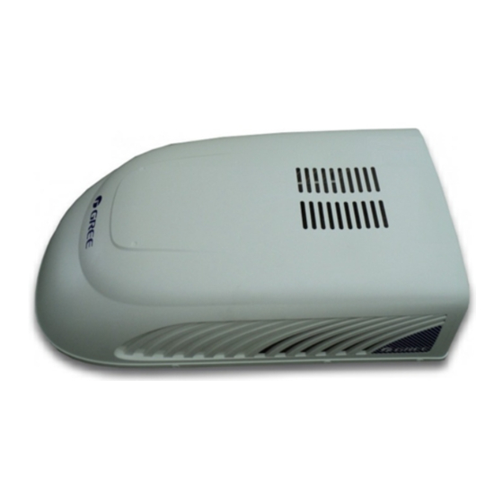
Recreational Vehicle
Air Conditioner
Owner's Manual
Operation & Installation
Models:
RVA-135R
RVA-135RHP
RVA-150R
RVA-150RHP
Air Conditioner,Please read this owner's
Advertisement
Table of Contents

Related Manuals for Gree RVA-135R


Summary of Contents for Gree RVA-135R
-
Page 1: Air Conditioner
Change for Life Recreational Vehicle Air Conditioner Owner's Manual Operation & Installation Models: RVA-135R RVA-135RHP RVA-150R RVA-150RHP Thank you for choosing Recreational Vehicle Air Conditioner,Please read this owner’s manual carefully before operation and keep it for future reference. V.121210... -
Page 2: Table Of Contents
CONTENTS 1. A FEW WORDS ABOUT YOUR NEW AIR CONDITIONING UNIT .........1 2. ELECTRIC DIAGRAM ......................2 3. PACKING LIST .........................3 4. SPECIFICATIONS ......................4 5. OPERATION OF WIRELESS REMOTE CONTROL ............5 6. CONTROL PANEL ......................9 7. INSTALLATION INSTRUCTION..................10 ..10 STEP 1-SELECTING AN INSTALLATION LOCATION & INSTALLING THE ROOF TOP AIR CONDITIONER ................13 STEP 2-INSTALLING THE CEILING ASSEMBLY ....................14... -
Page 3: A Few Words About Your New Air Conditioning Unit
A FEW WORDS ABOUT YOUR NEW AIR CONDITIONING UNIT Thank you for choosing the GREE Recreational Vehicle Air Conditioner. This manual will supply you with all the information for installation, operation and maintenance. Take a few minutes to discover how to get the most in cooling comfort and economic operation from your new air conditioner. -
Page 4: Electric Diagram
ELECTRIC DIAGRAM Ceiling Assembly CONNECTOR PRINTED CIRCUIT BOARD YEGN ROOM SWING1 SWING2 TERMINAL BLOCK BN(BK) BU(WH) YEGN(GN) STEPPING STEPPING ROOM TEMP. POWER MOTOR MOTOR SENSOR Notice: Use Copper Conductors Only. Roof Top Air Conditioner(heat pump 4-WAY TUBE OUT TUBE TRANSFORMER VALVE SENSOR SENSOR... -
Page 5: Packing List
PACKING LIST Packing List of Indoor Unit Name Quantity Remark Owner's Manual Bolt sub-assy M8X190 Sponge(air duct) Plate of air vent Remote control YS1FAF Double-sided gummed paper Remote control holder AAA1.5V batteries Tapping screw ST 4.2X9.5 TA Sunk screw (remote control holder) Packing List of Outdoor Unit Name Quantity... -
Page 6: Specifications
SPECIFICATIONS ● These specifications are for reference only. For actual data, please refer to the nameplate on the back of the unit. Model RVA-135R RVA-150R Power Supply (Ph/V/Hz) 1/115/60 Rated Cooling Capacity (BTU/h) 13500 15000 Cooling Power Input (Watts) 1350... -
Page 7: Operation Of Wireless Remote Control
OPERATION OF WIRELESS REMOTE CONTROL Name and Function of Wireless Remote Control Note: This wireless remote control is universal,and it could be used for many other models. The buttons that are not relevant to this unit will not be described below. Signal Transmitter SLEEP SLEEP button... - Page 8 Note: This wireless remote control is universal,and it could be used for many other models. The buttons that are not relevant to this unit will not be described below. + button Press this button to increase setting temperature, hold for more than 2 seconds to rapidly increase setting temperature.In AUTO mode, setting temperature is not adjustable.Setting temperature Range of...
- Page 9 Guide for Operation - General Operation 1. After powering on,press ON/OFF button,the unit will start to run.(Note:When it is powered on,the guide louver of indoor unit will close automatically.) 2. Press MODE button to select desired running mode. 3. Pressing + or - button, to set the desired temperature. 4.
- Page 10 1. Slightly press the place with , and push the cover along the arrow. 2. Take out the used batteries. (As show in figure) 3. Insert two new AAA1.5V batteries, and pay attention to the polarity. (As show in figure) 4.
-
Page 11: Control Panel
CONTROL PANEL Note: If the remote control is missing , operate on the control panel. Not available for cooling only model ON/OFF button MODE button Select the operation mode, AUTO, COOL, Operation starts when pressing this button, and DRY, FAN, HEAT(for heating model) or stops when pressing this button again. -
Page 12: Installation Instruction
INSTALLA TION INSTRUCTION BEFORE INSTALLATION Testrun the unit with proper power supply. Refer to the operation instruction section in the Owner’s Manual Operation & Installation. Make sure all the controls operate correctly then disconnect the power supply of the unit. ●... - Page 13 CASE B. If a roof vent opening is not used,a new opening(see figure 1)will be cut into the vehicl roof. A matching opening will also have to be cut into the interior vehicle ceiling,be careful when cutting the ceiling opening because if the ceiling opening is carpeted,snagging could occur. After the opening in the roof and interior ceiling are the correct size,a framed support structure must be placed between the exterior roof top and interior ceiling.The reinforced framed structure must follow the follwing guidelines:...
- Page 14 Location for Rubber Locator Gasket Location for Stick Height Varies to Make Unit Level Location for Rubber Locator Figure 2 Figure 4 Level Level Level Above or Below Above Level 10° Max Level Level 10° Max Below Level 0° Max Figure 3 NOTE AIR CONDITIONER DIMENSIONS (ROOF OF UNIT) 39.3''...
-
Page 15: Step 2-Installing The Ceiling Assembly
STEP 2-INSTALLING THE CEILING ASSEMBLY Make sure that you have properly matched the roof top air conditioner and interior ceiling assembly.The following step by step instructions must be performed in the following sequence to ensure proper installation. Carefully take the ceiling assembly out Secure the ceiling assembly frame to the of the carton (The remote control packed roof top air conditioner with the mounting... -
Page 16: Step 3-Electrical Wiring
STEP 3-ELECTRICAL WIRING ROUTING 115V AC WIRING WARNING Make sure that all power supply to the unit is disconnected before performing any work on the unit to avoid the possibility of shock or injury and/or damage to the equipment. After the interior ceiling assembly frame is properly secured to the roof top air conditioner, the following electrical connections must be performed. -
Page 17: Step 4-Completing The Installation
STEP 4-COMPLETING THE INSTALLATION To complete the installation and system checkout requirements, the following steps must be performed. Check the thermostat position. Make sure the thermostat is routed through the holding guide and is not touching any metal surface. Make sure the guide louver and the filters are properly positioned in the ceiling grille. Secure the ceiling grille to the ceiling assembly frame with 4 screws.(see Figure 10). -
Page 18: Troubleshooting Guide
TROUBLESHOOTING GUIDE If you have problems with your recreational vehicle air conditioner, check this guide before contacting your service representative. TROUBLE POSSIBLE CAUSE SOLUTION The unit can The unit may not be connected to the Check the power supply of the vehicle and make sure it is not start power supply correctly. -
Page 19: Normal Maintenance Procedures
NORMAL MAINTENANCE PROCEDURES ACTIVETY FREQUENCY Remove the cover and wash the condenser coil Twice a year. Clean the filter When the air conditioner FILTER CHECK (More frequent cleaning may be necessary light on. depending on the air quality) HOW TO REMOVE THE AIR FILTER Remove the air filters by pulling them as illustrated below.
Need help?
Do you have a question about the RVA-135R and is the answer not in the manual?
Questions and answers