Table of Contents
Advertisement
User and Maintenance Manual
for the Homeowner
and
Installation Instructions
for the Contractor
ACU-STEAM™ Humidifi er
by Thermolec
! !
Please read this manual carefully before beginning installation.
Important Notice to the Contractor :
Once the installation is complete, please leave this manual with the customer for future reference.
April 2007 V1.1
Advertisement
Table of Contents

Subscribe to Our Youtube Channel
Related Manuals for Thermolec Acu-Steam


Summary of Contents for Thermolec Acu-Steam
- Page 1 User and Maintenance Manual for the Homeowner Installation Instructions for the Contractor ACU-STEAM™ Humidifi er by Thermolec Please read this manual carefully before beginning installation. Important Notice to the Contractor : Once the installation is complete, please leave this manual with the customer for future reference.
- Page 3 Warnings and Disclaimer – Installation Precautions Please read and understand the warnings and instructions fully before you begin this installation and keep them handy for future reference. The manufacturer will assume no responsibility and the warranty will be void if the installer or the user does not adhere to the following precautions : This humidifi...
-
Page 4: View Of The Unit
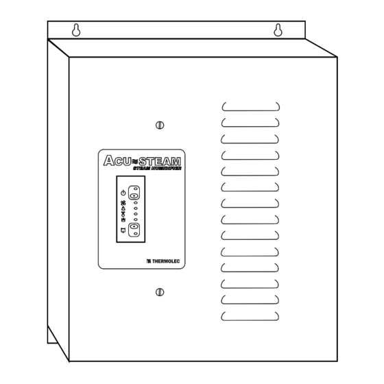
Instructions and User Manual for the Homeowner View of the unit Fig. 2a External view of the humidifi er. Water Tank Top View. Please see Fig. 2b. Fig. 2b Fig. 2b Water tank Side View. Please see Fig. 2c. ... - Page 5 Startup The startup of the humidifi er is done in as follows : • Put the main power ON at the electrical panel. The green pilot light comes ON. The humidifi er is ready to work. • Open the water supply valve. •...
- Page 6 If you installed an ACU-STEAM humidistat and an outdoor sensor, this adjustment will be done automatically. The outdoor sensor reduces the setting of the humidistat according to the outdoor temperature during cold days without having to set the humidistat knob manually.
- Page 7 Fig. 5a Fig. 5a The ACU-STEAM humidistat also has two pilot lights to indicate the current status. The green light is lit when the humidistat is demanding for humidity, thus activating the boiling cycle. The red light indicates a warning and reproduces the same warning code as the red light on the humidifi er control panel.
- Page 8 Warning Red light An abnormal condition occurred. Please refer to the error code table in Section 7. Steam White light The humidifi er is heating water to produce steam. Filling cycle Blue light The electric water valve is open thus fi lling the humidifi...
-
Page 9: What To Do If A Malfunction Occurs
What To Do if a Malfunction Occurs Shut the main power OFF and restart the humidifi er to see if the error code disappears. If you see a water leak, follow the water supply tube and close the valve installed on the water pipe located near the humidifi... -
Page 10: Cleaning The Tank
The humidifi er will stop and drain. Please note that when using an ACU-STEAM electronic humidistat, if the relative humidity is extremely low the humidifi er may still run with the knob at the minimum setting because of a range limiter inside the cover. If this occurs you will need to remove the humidistat cover by pulling it off and turn the knob completely counter-clockwise. - Page 11 Pull the plastic tube attached to the bottom of the unit out of the rigid drain pipe on the wall. You do not have to remove the plastic tube attached to the bottom of the pan. Remove the overfl ow pan from the unit by lifting the front off the screw and pulling it towards you.
- Page 12 Put the overfl ow pan under the tank by sitting it back on its holding screws. 8.10 Reconnect the white wire of the overfl ow sensor on the water pan. 8.11 Put the overfl ow and main drain tubes back into the rigid drain pipe attached to the wall. 8.12 Put the cover back on the humidifi...
- Page 13 Preventative Maintenance Preventive maintenance to be performed every two years. In order to avoid problems due to accumulation of deposits, we suggest that you replace the centre metal tube, the silicone drain tube and the low level sensor. We also suggest you replace the round o-ring gasket around the tank.
-
Page 14: Warranty
Thermolec responsibility shall be limited in any case to the replacement or repair, in its factory or in the fi eld, by its own personnel or by others chosen by Thermolec, at its option, of such steam humidifi er or parts thereof, as shall prove to be defective within the warranty period. -
Page 15: Unpacking The Unit
Detailed Instructions for the Contractor Unpacking the Unit 11.1 Contents Please inspect the carton’s contents and report any missing parts or damage immediately. 1 Humidifi er 1 Main Drain tube (32” long – already installed and coiled inside the unit) 1 Steam hose (4 feet long x 1 inch I.D.) 1 Steam diffuser (12”, 18”... - Page 16 Dimensions and Available Models Fig. 12a 12.1 Humidifi er dimensions 11 5/8” 11 5/8” 14” 14” 9” 9” 13” 13” Fig. 12b 12.2 Available models Capacity Capacity Model Model Lbs/Hr Lbs/Hr Power Power Voltage Voltage Current Current (Kg/Hr) (Kg/Hr) (Kw) (Kw) Acu-5 Acu-5...
- Page 17 Detailed View and Wiring Fig. 13a View of the top of the unit. Electric Electric Black Black Steam Outlet Steam Outlet Valve Valve Heating Heating Element Element Black Black Manual Manual Thermal Thermal High Level High Level Cut-out Cut-out Low Level Low Level Level Level...
- Page 18 View and list of the wire harness by color and function. Please see Fig. 13b & Fig. 13c. Overflow Sensor Overflow Sensor Ground Ground connection connection connection connection On/Standby LED On/Standby LED On/Standby On/Standby Element Element Switch Switch Relay Relay Fan LED Fan LED Neutral...
- Page 19 Note: Please read sections 14 and 15 before proceeding. Installing the Steam Hose and the Steam Diffuser 14.1 Proper installation of the diffuser and steam hose is critical for the trouble-free operation of the humidifi er. Please fi nd an accessible location on the duct and make sure you have a minimum length of 35”...
- Page 20 14.4 After installing the humidifi er (Section 15) use the second supplied hose clamp, to install the other end of the steam hose (4 feet long) onto the steam outlet on the top of the water tank and tighten it. Never try to reduce the diameter of the steam hose or any added rigid piping.
-
Page 21: Installing The Humidifi Er
Installing the Humidifi er For ease of service, keep a minimum space of 24” in front of the unit. 15.1 Remove the cover by turning the two 1/4 turn screws to the left and pull the cover towards you. 15.2 Remove the white wire connected on the water pan at the bottom of the unit. - Page 22 The two fl exible tubes coming from the humidifi er and which will be inserted in the rigid pipe, require a minimum free vertical length of 18”. It is very important to leave an air gap between the rigid pipe and the tubes to allow the siphon to function properly.
- Page 23 Installing the Water Supply Valve Important Notes : • Turn off the main water supply before beginning. • The supply valve is designed to be installed on a copper pipe only. Please see Fig.16a. If the plumbing is made with plastic pipe, the saddle valve is not appropriate because it could squash or crack the plastic tube. It should be replaced by a special valve (not supplied) suited for plastic.
- Page 24 16.7 Push the tube fully into the valve. Tighten the brass compression nut with small wrenches, without stripping, using the double wrench method in order to apply the torque on the fi tting only and not on the valve assembly. Please see Fig. 16d. Fig.
- Page 25 Installing the Air Pressure Probe 17.1 The pressure probe (also called a Pitot tube) connected to the pressure differential switch inside the unit checks whether there is enough air pressure in the warm air duct to activate the humidifi er. 17.2 The probe has to be installed in the warm air duct, as close as possible to the humidifi...
-
Page 26: Making Electrical Connections
Making Electrical Connections NOTE : All internal wiring is done at the factory. All external wiring shall be done by a qualifi ed electrician and must conform to procedures, regulations and local codes. 18.1 A dedicated breaker in the main panel (or fused disconnect) must be installed. 18.2 The voltage of the available power supply must be the same as the one required by the humidifi... - Page 27 Installing and Connecting the Humidistat 19.1 See wiring diagrams in section 21 for proper connection. If you are using an ACU-STEAM electronic humidistat with outdoor sensor please refer to the instructions included with the humidistat. If you decide to use a standard mechanical humidistat, connect the mechanical humidistat between the terminals marked GND (ground) &...
-
Page 28: Start-Up And Test Procedure
Start-up and Test Procedure 20.1 Take the 5/16 dia. plastic tube previously uncoiled and push one end on the connector located at the bottom of the overfl ow pan. Please see Fig. 20a and Fig.20b. Fig. 20a Fig. 20a Fig. 20b Fig. - Page 29 20.13 As water evaporates in the tank, the electric valve opens as needed to maintain the proper water level. 20.14 When the humidity reaches the desired level the humidifi er stops producing steam and automatically drains. In order to eliminate the residues and keep the tank as clean as possible, the humidifi er also drains after a certain number of boiling –...
-
Page 30: Wiring Diagrams
Wiring diagrams Page 28... - Page 31 120VAC Page 29...
- Page 32 Page 30...
-
Page 33: Detailed Error Codes
Detailed Error Codes Page 31...
Need help?
Do you have a question about the Acu-Steam and is the answer not in the manual?
Questions and answers