Chapters
Table of Contents
Troubleshooting

Related Manuals for Yamaha AVX-S80


Summary of Contents for Yamaha AVX-S80
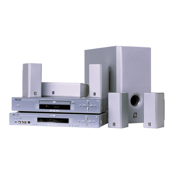
- Page 1 HOME THEATER SOUND SYSTEM AVX-S80 VOLUME STANDBY/ON STEREO INPUT INPUT MODE SILENT VIDEO2 – MEMORY AUTO/MAN'L A/B/C/D/E PRESET/BAND PRESET/TUNING PHONES VIDEO AUDIO OPTICAL AVX-S80: AVR-S80 + NX-S80S + NX-S80C + SW-S80 OWNER’S MANUAL...
-
Page 2: Important Safety Instructions
IMPORTANT SAFETY INSTRUCTIONS Ventilation – Slots and openings in the cabinet are provided for ventilation and to ensure reliable operation of the CAUTION product and to protect it from overheating, and these RISK OF ELECTRIC SHOCK openings must not be blocked or covered. The openings DO NOT OPEN should never be blocked by placing the product on a bed, sofa, rug, or other similar surface. - Page 3 “ON”, please try to eliminate the problem by using one requirements. Modifications not expressly approved of the following measures: by Yamaha may void your authority, granted by the FCC, to use the product. Relocate either this product or the device that is being affected by the interference.
- Page 4 YAMAHA will not be held responsible for any damage resulting from use of this system with a voltage other than specified. 13 To prevent damage by lightning, disconnect the power cord from The name plate is located on the bottom of AVR-S80.
-
Page 5: Table Of Contents
CONTENTS INTRODUCTION REMOTE CONTROL FEATURES INTRODUCTION ............... 2 OPERATING OTHER COMPONENTS USING THE FEATURES ................2 REMOTE CONTROL ............32 CHECKING THE ACCESSORIES ........3 Setting the manufacturer code ......... 32 INSTALLING BATTERIES IN THE REMOTE Other component controlling functions ......33 CONTROL ................ -
Page 6: Introduction
Also, the SILENT CINEMA DSP program allows you to enjoy the sound field even through the headphones. Since the AVX-S80 consists of an AV receiver, a center speaker, front speakers, rear speakers and a subwoofer, you can enjoy stronger bass and surround effects as well as a good balance throughout the speakers. Moreover, the One-touch connection of the speaker connectors designed exclusively for this system allows you to easily connect the speakers. -
Page 7: Checking The Accessories
CHECKING THE ACCESSORIES Check your package to make sure it contains the following items. AVR-S80 NX-SW80 (NX-S80S x4, NX-S80C, SW-S80) Fasteners (2 sets) Screws Remote control Batteries (x2) AM loop antenna Non-skid pads (AA, R06, UM-3) for the center (2 sets: 16 pieces) (4 pieces) speaker Mounting... -
Page 8: Controls And Functions
CONTROLS AND FUNCTIONS Front panel VOLUME STANDBY/ON STEREO INPUT INPUT MODE SILENT VIDEO2 – MEMORY AUTO/MAN'L A/B/C/D/E PRESET/BAND PRESET/TUNING PHONES VIDEO AUDIO OPTICAL 1 STANDBY/ON 7 VIDEO 2 jacks Turns this system on, or set it to the standby mode. When These jacks are for connecting a video component such as you turn this system on, you will hear a click and there a camcorder or video game player. -
Page 9: Remote Control
CONTROLS AND FUNCTIONS Remote control 3 CODE SET This section explains the function of each button on the remote control when you operate this system as an Used when setting up the manufacturer code. amplifier. Make sure that the AMP mode is selected 4 DSP program buttons before starting operation. -
Page 10: Using The Remote Control
CONTROLS AND FUNCTIONS I Using the remote control – Approximately 6 m (20 feet) 30° 30° Handling the remote control • Do not spill water or other liquids on the remote control. • Do not drop the remote control. • Do not leave or store the remote control in the following types of conditions: –... -
Page 11: Front Panel Display
CONTROLS AND FUNCTIONS Front panel display 2 3 4 9 0 o VIRTUAL DVD/CD VIDEO 1VIDEO 2 VCR TUNER STEREO AUTO TUNED SILENT MATRIX PS PTY RT CT MOVIE THTR 12ENTERTAINMENT DTSDOLBY DIGITALPRO LOGIC B. BOOST DIGITAL PTY HOLD MEMORY PRO LOGIC 8 8 8 8 8 8 8 8 8 8 8 8 8 8 SLEEP... -
Page 12: Preparation Steps
PREPARATION STEPS In order to enjoy sound and video images with this sound Before connecting components system, follow the procedures as described below. See • Do not connect this system or other components to the each page for details. mains power until all connections between the components have been completed. -
Page 13: Speaker Setup
SPEAKER SETUP This system has been designed to provide the best sound- Speaker placement field quality with a 5-speaker system, using front left and right speakers, rear left and right speakers and a center Refer to the following diagram when you place the speaker. -
Page 14: Installing The Speakers
SPEAKER SETUP I Mounting the front and rear Installing the speakers speakers on a wall When mounting the speakers on a wall, use the holes on I Placing the center speaker the speakers’ back panels. Place the speaker on TV whose top is flat or on the floor Fasten screws into a firm wall or wall under the TV or inside the TV rack so that it is stabilized. - Page 15 (option) speaker stand By using the Yamaha Speaker Stand SPS-80, speakers can be placed on the floor. (Two stands make a set.) The provided mounting bracket with 1 pair of screw holes (at an interval of 60 mm) can be used to mount the speaker on a speaker stand.
-
Page 16: Connections
CONNECTIONS Anti-dust cap Connecting TV and audio/video Remove the cap covering the OPTICAL jack when components connecting an optical cable to an OPTICAL jack on the rear panel of this system. Safely store the cap and always I Types of audio jacks re-insert it in the terminal when the terminal is not in use. - Page 17 CONNECTIONS I The connection example Use the following included or commercially available connection cables. For Audio component For Video Component Video pin cable Optical cable For AV component Audio/Video cable The connection example shown below is just an example. Connect in accordance with the components you have. INPUT OUTPUT INPUT...
-
Page 18: Connecting The Antennas
• A properly installed outdoor antenna provides clearer reception than an indoor one. If you experience poor reception quality, an outdoor antenna may improve the quality. Consult the nearest authorized YAMAHA dealer or service center about the outdoor antennas. Notes •... -
Page 19: Connecting The Speakers
CONNECTIONS Connecting the speakers Connect the included speakers to the AV receiver (AVR-S80) using the included speaker cables and system control cable as shown below. AV receiver As this terminal is used for testing at the (AVR-S80) factory, do not connect any equipment to this terminal. - Page 20 CONNECTIONS I Using commercially available The back of the (RED) Subwoofer speakers and speaker cables You can use commercially available speaker cables and speakers except for a subwoofer. If you use them, note the (RED) following. • Use the speaker whose impedance is 6Ω or higher. When using the speaker whose impedance is lower than 6Ω, the protection circuit may start working or this Connector...
-
Page 21: Connecting To An External Amplifier
CONNECTIONS Connecting to an external Connecting the AC power cord amplifier Plug in this system to the wall outlet. I Memory back-up If you want to increase the power output to the speakers, or want to use another amplifier, connect an external The memory back-up circuit prevents the stored data from amplifier to the 6CH PREOUT jacks as follows. -
Page 22: Adjusting Speaker Output Levels
ADJUSTING SPEAKER OUTPUT LEVELS This section explains how to adjust speaker output levels LEFT RIGHT using the test tone generator. When this adjustment is complete, the output level heard at the listening position should be the same from each speaker. This is important CENTER for best performance of the digital sound field processor, SUBWOOFER... -
Page 23: Basic Playback
BASIC PLAYBACK Basic operations Adjust the volume to the desired level. The volume level is displayed digitally. Example: –70 dB You can play the software loaded on the audio and video Control range: VOLUME MUTE (minimum) to components connected to this system. 0 dB (maximum) Note POWER... -
Page 24: This System
BASIC PLAYBACK I When you have finished using this system • When AUTO is selected, this system automatically determines the type of signal. If this system detects a Dolby Digital or Press STANDBY/ON on the front panel (POWER ( DTS signal, the decoder automatically switches to the on the remote control) to set this system in the standby appropriate setting. -
Page 25: Selecting A Sound Field Program
BASIC PLAYBACK Selecting a sound field program This system’s built-in DSP (Digital Sound field Processor) can simulate various acoustic environments, including a concert hall and movie theater, with its 9 sound field programs. For the best results, choose a program appropriate for the selected audio source. - Page 26 BASIC PLAYBACK Program Features ENTERTAINMENT/ This program adds a deep and spatial feeling to video game sounds. Game ENTERTAINMENT/ This program produces an enthusiastic atmosphere and lets you feel as if you are at an actual Concert Video jazz or rock concert. TV SPORTS With this program, you can enjoy watching various TV programs such as news, variety shows, music programs or sports programs.
-
Page 27: Table Of Program Names For Each Input Format
BASIC PLAYBACK I Table of Program Names for Each Input Format This system automatically chooses the appropriate decoder and DSP sound field pattern according to the input signal format. 2 channel 5.1 channel 6.1 channel * Input DOLBY DIGITAL DOLBY DIGITAL ANALOG, PCM, Program + Matrix 6.1... - Page 28 BASIC PLAYBACK I Selecting PRO LOGIC II Notes You can enjoy the 2-channel sources decoded into five • Some Dolby Digital Surround EX or DTS ES software may not contain the signal that is necessary for this system to switch to discrete channels by selecting PRO LOGIC II in program the Matrix 6.1 decoding mode.
-
Page 29: Normal Stereo Reproduction
BASIC PLAYBACK I SILENT CINEMA DSP • Format: You can enjoy a powerful sound field similar to what you The type of an input signal. When digital input is not known, could expert from actual speakers with SILENT the mode is set to the analog mode. CINEMA DSP. -
Page 30: Recording
RECORDING I Timer playback/recording Recording adjustments and other operations are performed from the recording components. Refer to the This system can perform playback or recording with an operation instructions for these components. external timer (not supplied). Refer to the operating instructions for the component and the timer to be used. -
Page 31: Tuning
TUNING I Manual tuning Indication on the front panel (example) Preset station If the signal from the station you want to select is weak, number Reception band you must tune in to it manually. TUNER Select TUNER and the reception band C 1 : A M 6 3 0 k H z following steps 1 and 2 described in... -
Page 32: Presetting Stations
TUNING Automatic preset tuning options Presetting stations You can select the preset group and number from which this system will store FM stations and/or begin tuning toward lower or higher frequencies. MEMORY PRESET/BAND Follow steps 1 and 2 described in “Automatically presetting stations (for FM VOLUME stations)”... -
Page 33: Exchanging Preset Stations
TUNING Press MEMORY on the front panel while the Tuning in to a preset station “MEMORY” indicator is flashing. The station band and frequency appear on the front You can tune any desired station simply by selecting the panel display with the preset group and number you preset station number under which it was stored. -
Page 34: Receiving Rds Stations (U.k. And Europe Models Only)
RECEIVING RDS STATIONS (U.K. and Europe models only) RDS (Radio Data System) is a data transmission system Description of RDS data by FM stations in many countries. This system can receive, PS, PTY, RT and CT data when RDS data contains various information such as PS receiving RDS broadcasting stations. -
Page 35: Changing The Rds Mode
RECEIVING RDS STATIONS (U.K. and Europe models only) Changing the RDS mode PTY SEEK function The four modes are available in this system for displaying If you select the desired program type, this system RDS data. When an RDS station is being received, PS, automatically searches all preset RDS stations that are PTY, RT and/or CT mode indicators that correspond to broadcasting a program of the required type. -
Page 36: Operating Other Components Using The Remote Control
2-digit DVD player on the remote control allows you to operate manufacturer code for the component to be not only the AVX-S80 but also your TV, VCR or DVD controlled using the numeric buttons. player using the remote control. -
Page 37: Other Component Controlling Functions
OPERATING OTHER COMPONENTS USING THE REMOTE CONTROL Other component controlling functions By pressing an input selector button (TV, VCR, DVD/CD) for which the manufacturer code is set, the functions of the remote control buttons change for controlling the corresponding component as follows. Controlling a TV 1 TV (POWER) Turns the TV on, or set it to the standby mode. - Page 38 OPERATING OTHER COMPONENTS USING THE REMOTE CONTROL Controlling a DVD player 1 AV (POWER) • The buttons on the remote control whose names are Press to turn on the DVD player or set it to the standby written in green are operation buttons for a DVD mode.
-
Page 39: Set Menu
SET MENU The SET MENU consists of 9 items including the speaker Adjusting the items on the SET mode setting. Choose the appropriate item and adjust or MENU select the values as necessary. Adjustment should be made with the remote control. •... -
Page 40: Speaker Set (Speaker Mode Settings)
SET MENU I 1B FRONT (front speaker mode) 1 SPEAKER SET (speaker mode Choices: LARGE, SMALL settings) LARGE Select this if you have large front speakers. The entire Use this feature to select suitable output modes for your range of the front left and right channel signal is directed speaker configuration. -
Page 41: Lfe Level
SET MENU I 1D BASS (LFE/bass out mode) 2 LFE LEVEL LFE signals carry low-frequency effects when this system decodes a Dolby Digital or DTS signal. Low-frequency Use this feature to adjust the output level of the LFE signals are defined as 90 Hz and below. The Low- (low-frequency effect) channel when playing back a frequency signals can be directed to both front left and Dolby Digital or DTS signal. -
Page 42: Sp Dly Time (Speaker Delay Time)
SET MENU 3 SP DLY TIME (speaker delay 4 D. RANGE (dynamic range) time) Use this feature to adjust the dynamic range. This setting is effective only when this system is decoding Dolby Use this feature to adjust the delay of the center channel Digital signals. -
Page 43: Input Mode (Initial Input Mode)
SET MENU 7 INPUT MODE (initial input mode) Use this feature to designate the input mode for sources connected to the digital (optical) input jacks when you turn on this system. Choices: AUTO, LAST AUTO Select this to allow this system to automatically detect the type of input signal and select the appropriate input mode. -
Page 44: Adjusting The Level Of The Effect Speakers
ADJUSTING THE LEVEL OF THE EFFECT SPEAKERS I For 5ch Stereo You can adjust the output level of each effect speaker (center, rear left and right, and subwoofer) while listening You can adjust the volume level for each channel in 5- to a source. -
Page 45: Changing The Parameter Settings For Dsp Programs
CHANGING THE PARAMETER SETTINGS FOR DSP PROGRAMS The following table shows factory-set delay time. Adjusting the delay time Program Preset value (ms) You can adjust the time difference between the beginning CONCERT HALL of the sound from the front speakers and the beginning of JAZZ CLUB the sound effect from the rear speakers. -
Page 46: Adjusting The Parameter Settings For Pro Logic Ii Music
CHANGING THE PARAMETER SETTINGS FOR DSP PROGRAMS Adjusting the parameter settings for PRO LOGIC II Music I Changing parameter settings I PRO LOGIC II Music parameter descriptions You can adjust the values of PRO LOGIC II Music parameters so the sound fields are recreated accurately in PANORAMA your listening room. -
Page 47: Troubleshooting
Refer to the chart below when this system does not function properly. If the problem you are having is not listed below or if the instruction below does not help, set this system to the standby mode, disconnect the power cord, and contact the nearest authorized YAMAHA dealer or service center. I General... - Page 48 TROUBLESHOOTING Problem Cause Remedy Refer to page The output level of the center speaker is set to Raise the level of the center speaker. No sound from the minimum. center speaker. “1A CENTER” on the SET MENU is set to Select the appropriate mode for your center NON.
- Page 49 TROUBLESHOOTING I Tuner Problem Cause Remedy Refer to page Previously preset The preset stations are cleared. Pre-set the stations once again. stations cannot be tuned in. FM stereo reception is The characteristics of FM stereo Check the antenna connections. noisy. broadcasts may cause this problem Try using a high-quality directional FM when the transmitter is too far away or...
-
Page 50: Glossary
Compressed PCM differences in the sound heard as well. Based on a wealth signals are called packed PCM (PPCM). of actually measured data, YAMAHA CINEMA DSP uses YAMAHA original sound field technology to combine Matrix 6.1 Dolby Pro Logic, Dolby Digital and DTS systems to The system incorporates Matrix 6.1 decoder for Dolby... -
Page 51: Specifications
SUBWOOFER (100 Hz, 10% THD, 5 Ω) • Subwoofer .................... 50 W Model Name ..............SW-S80 Type ..Advanced YAMAHA Active Servo Technology system • Total Harmonic Distortion Speaker .... 16 cm (6-1/2 inch) woofer, magnetically shielded FRONT L/R (20 W, 1 kHz) ..........0.05 % Impedance ................ - Page 52 LIST OF MANUFACTURER’S CODES Signature Sony (Device Code: 2) Sylvania 97 25 Telefunken 69 64 65 66 Yamaha 99 92 Thomson 23 66 Admiral 92 93 Toshiba 92 26 67 Aiwa 94 76 83 Videch 97 42 Akai 95 96...
- Page 53 76 77 Thorn 93 96 Toshiba 35 69 89 Universum 96 27 76 W.WHouse Wards 95 96 36 62 (Device Code: 4) Yamaha 99 22 23 DENON 99 24 Funai HITACHI KENWOOD Mitsubishi Onkyo 32 33 34 Panasonic 99 35...
- Page 54 YAMAHA ELECTRONICS (UK) LTD. YAMAHA HOUSE, 200 RICKMANSWORTH ROAD WATFORD, HERTS WD1 7JS, ENGLAND YAMAHA SCANDINAVIA A.B. J A WETTERGRENS GATA 1, BOX 30053, 400 43 VÄSTRA FRÖLUNDA, SWEDEN YAMAHA MUSIC AUSTRALIA PTY, LTD. 17-33 MARKET ST., SOUTH MELBOURNE, 3205 VIC., AUSTRALIA...
- Page 55 Connecting to a TV (monitor), DVD player, video camera and video game player AVX - S 8 0 DVD player TV (monitor) CONNECTION GUIDE VIDEO INPUT PCM/ DIGITAL S VIDEO MIXED 2CH OPTICAL SUBWOOFER COMPONENT VIDEO AC IN DIGITAL VIDEO AUDIO OUT AUDIO OUT VIDEO OUT...
- Page 56 DVD/VIDEO CD/CD PLAYER DVD-S80 NATURAL SOUND DVD PLAYER DVD-S80 STANDBY/ON Before connecting, operating or adjusting this product, please read these instructions completely. Please keep this manual for future reference. OWNER’S MANUAL...
- Page 57 FCC requirements. Modifications not expressly approved by THIS PRODUCT UTILIZES A LASER. Yamaha may void your authority, granted by the FCC, to use the product. USE OF CONTROLS OR ADJUSTMENTS OR PERFORMANCE 2. IMPORTANT: When connecting this product to accessories and/or OF PROCEDURES OTHER THAN THOSE SPECIFIED HEREIN another product use only high quality shielded cables.
- Page 58 PRECAUTIONS Table of contents Getting started Before using this unit please read these operating instructions carefully. Take special care to follow the warnings indicated on the unit itself as well PRECAUTIONS ........03 as the safety suggestions listed below.
-
Page 59: Accessories
Accessories Please check and identify the supplied accessories. ∏ Remote control ∏ Batteries (k k k k k 2) ∏ Power cable ∏ Audio/Video cable for remote control Note The included power cable is for use with this unit only. Do not use it with other equipment. -
Page 60: Video Connection
Connection Video connection This unit equips three types of video jacks as follows: 1. VIDEO jack 3. COMPONENT VIDEO OUT jacks This jack transmits conventional composite video signal. Connect this jack These jacks transmit color difference and luminance separately and to your AV amplifier so that you can switch the both audio and video inputs provide the best quality picture. -
Page 61: The Remote Control
The remote control ∫ Batteries Do not: ≥mix old and new batteries. ≥use different types at the same time. R6, AA, UM-3 ≥heat or expose to flame. ≥take apart or short circuit. ≥attempt to recharge alkaline or manganese batteries. ≥use batteries if the covering has been peeled off. Mishandling of batteries can cause electrolyte leakage which can damage items the fluid contacts and may cause a fire. -
Page 62: Control Reference Guide
Control reference guide Page 1 Standby/on switch (POWER Í/I) ......06 Press to switch the unit from on to standby mode or vice versa. In standby mode, the unit is still consuming a small amount of power. -
Page 63: Basic Play
Basic play To stop play Press [∫] ( page 9, Resume function). To pause play Press [;] during play. Press [1] (PLAY) to restart play. ∫ ∫ Auto standby 6, 5 :, 9 The unit switches to standby mode after about 30 minutes in the stop mode. TOP MENU MENU Notes... -
Page 64: Skipping Chapters Or Tracks
Skipping chapters or tracks Resume function [DVD-V] [CD] [VCD] [DVD-V] [CD] [VCD] During play or while paused (When the elapsed play time is displayed) Press [:] or [9]. The position you stopped play at is recorded by the unit when “!” is flash- ing on the display. -
Page 65: Convenient Features
Convenient features Program play Remote control only You can select up to 32 tracks/chapters to play in the order you choose. ∫ While stopped 6, 5 Press [PROGRAM]. e.g. CD TOP MENU MENU Choose a track, then press ENTER. PROGRAM Track Time 3, 4, 2, 1... -
Page 66: Random Play
Using the tree screen to find a group Random play [DVD-V] [CD] [VCD] Press [1] while a track is highlighted to display the tree screen. Remote control only File list While stopped Tree MP3 music G 8/16 Press [RANDOM]. 001 My Favorite Total 123 001 Brazilian pops 002 Chinese pops... -
Page 67: Increasing Your Enjoyment Of Movies
Increasing your enjoyment of movies Subtitles During play Press [SUBTITLE]. The number changes each time you press the button. English French 3, 4, 1 I love you Je t’aime ANGLE ≥In some cases, the subtitle language is not changed to the selected one SUBTITLE AUDIO immediately. -
Page 68: Using On-Screen Menu Icons
Using On-Screen Menu Icons On-Screen Menu Icons are menus that contain information about the disc or unit. These menus allow you to perform operations by changing this information. Common procedures [DVD-V] [CD] [VCD] Remote control only Press [ON SCREEN]. 3, 4, 2, 1 Each time you press the button: ENTER Disc information... -
Page 69: Disc Information
Using On-Screen Menu Icons Disc information Unit information e.g. DVD-Video Play menu e.g. MP3 disc a A-B repeat [DVD-V] [CD] [VCD] You can repeat a section between points A and B within a title or track. [ENTER] (start point) [ENTER] (finish point) To cancel: [ENTER] e.g. - Page 70 Audio menu Display menu a 4:3 TV ZOOM [DVD-V] a ADVANCED SURROUND [DVD-V] (Dolby Digital, 2-channel or over only) ON()OFF Expand a letterbox picture ( page 6) to fill more of a regular 4:3 Use ADVANCED SURROUND Virtual Surround Sound to enjoy a aspect television (The sides of the picture are cut off when you select surround-like effect if you are using 2 front speakers.
-
Page 71: Changing Settings
Changing settings This chart shows the settings for this unit. Change the settings to suit your preferences and to suit the unit to the environment in which it is being used. These settings are retained in memory until they are changed, even if the unit is turned off. See page 17 for details on menu operation. Menus Items Options... -
Page 72: Common Procedures
Entering a password (Ratings) [DVD-V] The password screen is shown when you select levels 0 to 7. 1. Input a 4-digit password with the numbered buttons and press [ENTER]. ≥If you enter a wrong number, press [CANCEL] to erase it before you press [ENTER]. -
Page 73: Troubleshooting Guide
Troubleshooting guide Before requesting service, make the below checks. If you are in doubt about some of the check points, or if the remedies indicated in the chart do not solve the problem, consult your dealer for instructions. Power Page No power. -
Page 74: Glossary
Unit displays Page “NO PLAY” ≥You inserted a disc the unit cannot play; insert one it can. “CHECK DISC” ≥Disc is dirty. Wipe the disc clean. – “H∑∑” ≥Trouble is likely to have occurred. The number following “H” depends on the status of the unit. –... -
Page 75: Specifications
YAMAHA ELECTRONIK EUROPA G.m.b.H. SIEMENSSTR. 22-34, 25462 RELLINGEN BEI HAMBURG, F.R. OF GERMANY YAMAHA ELECTRONIQUE FRANCE S.A. PA PARIS-EST RUE AMBROISE CROIZAT CROISSY-BEAUBOURG BP70-77312 MARNE LAVALLEE, CEDEX 2 FRANCE YAMAHA ELECTRONICS (UK) LTD. YAMAHA HOUSE, 200 RICKMANSWORTH ROAD WATFORD, HERTS WD1 7JS, ENGLAND YAMAHA SCANDINAVIA A.B.
Need help?
Do you have a question about the AVX-S80 and is the answer not in the manual?
Questions and answers