Table of Contents
Advertisement
Quick Links
Advertisement
Table of Contents

Related Manuals for Supero Supero X9QR7-TF+


Summary of Contents for Supero Supero X9QR7-TF+
- Page 1 X9QR7-TF+ X9QRi-F+ USER’S MANUAL Revision 1.0a...
- Page 2 This product, including software and docu- mentation, is the property of Supermicro and/or its licensors, and is supplied only under a license. Any use or reproduction of this product is not allowed, except as expressly permitted by the terms of said license.
-
Page 3: About This Motherboard
Manageability Engine (ME), Rapid Storage Technology, Digital Media Interface (DMI), PCI-E Gen. 3.0 and 1600 MHz DDR3 memory. These features will greatly enhance system performance. This motherboard is ideal for HPC/Cluster/Database server platforms. Please refer to our Website (http://www.supermicro.com) for CPU and memory support updates. Manual Organization Chapter 1 describes the features, specifications and performance of the mother- board, and provides detailed information about the Intel C602 chipset. -
Page 4: Conventions Used In The Manual
X9QR7-TF+/X9QRi-F+ Motherboard User’s Manual Conventions Used in the Manual Pay special attention to the following symbols for proper system installation and to prevent damage to the system or injury to yourself: Danger/Caution: Instructions to be strictly followed to prevent catastrophic system failure or to avoid bodily injury Warning: Important information given to ensure proper system installation or to prevent damage to the components... -
Page 5: Contacting Supermicro
Super Micro Computer, Inc. 980 Rock Ave. San Jose, CA 95131 U.S.A. Tel: +1 (408) 503-8000 Fax: +1 (408) 503-8008 Email: marketing@supermicro.com (General Information) support@supermicro.com (Technical Support) Website: www.supermicro.com Europe Address: Super Micro Computer B.V. Het Sterrenbeeld 28, 5215 ML... -
Page 6: Table Of Contents
X9QR7-TF+/X9QRi-F+ Motherboard User’s Manual Table of Contents Preface Chapter 1 Overview Overview ......................1-1 Processor and Chipset Overview..............1-11 Special Features ................... 1-12 PC Health Monitoring ..................1-12 ACPI Features ....................1-13 Power Supply ....................1-13 Super I/O ....................... 1-14 Advanced Power Management ..............1-14 Intel Intelligent Power Node Manager (IPNM) .......... - Page 7 Table of Contents Ethernet Ports ..................2-17 Unit Identifier Switch ................2-18 Front Control Panel ..................2-19 Front Control Panel Pin Definitions............... 2-20 NMI Button ....................2-20 Power LED ....................2-20 HDD LED ....................2-21 NIC1/NIC2 LED Indicators ............... 2-21 Overheat (OH)/Fan Fail/PWR Fail/UID LED ..........
- Page 8 X9QR7-TF+/X9QRi-F+ Motherboard User’s Manual SAS2 Ports ....................2-36 Chapter 3 Troubleshooting Troubleshooting Procedures ................3-1 Before Power On .................... 3-1 No Power ......................3-1 No Video ......................3-2 System Boot Failure ..................3-2 Losing the System’s Setup Configuration ............3-2 Memory Errors ....................
-
Page 9: Chapter 1 Overview
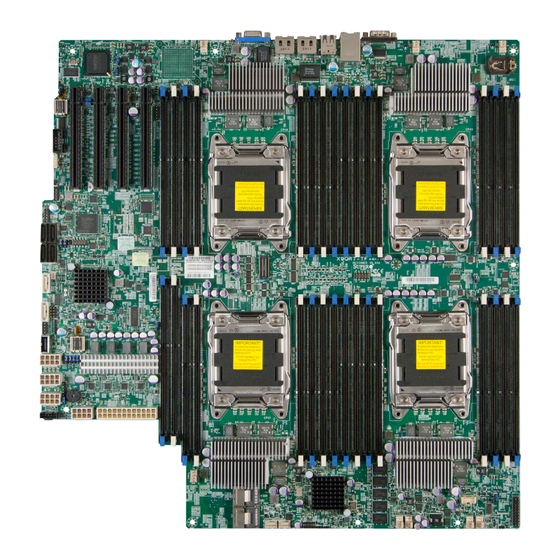
Checklist Congratulations on purchasing your computer motherboard from an acknowledged leader in the industry. Supermicro boards are designed with the utmost attention to detail to provide you with the highest standards in quality and performance. Please check that the following items have all been included with your motherboard. - Page 10 X9QR7-TF+/X9QRi-F+ Motherboard User’s Manual Motherboard Image Note: All graphics shown in this manual were based upon the latest PCB Revision available at the time of publishing of the manual. The motherboard you've received may or may not look exactly the same as the graphics shown in this manual.
-
Page 11: Motherboard Layout
Rev. 1.02 UFBMC1 CPU4 CPU3 CPU1 CPU1 CLPD CPU2 CPU1 JPW5 CPU1 CPU1 LS2E1 JPW4 JPW3 JPW2 JPW1 JPI2C1 SAS CTRL FAN6 FAN5 J3 J2 JOH1 Note: For the latest CPU/Memory updates, please refer to our Website at http://www.supermicro.com/products/motherboard/ for details. - Page 12 X9QR7-TF+/X9QRi-F+ Motherboard User’s Manual X9QR7-TF+/X9QRi-F+ Quick Reference USB0/1 COM1 LAN1 LAN2 USB2/3 BMC CTRL LAN CTRL IPMI_LAN X9QR7-TF+/X9QRi-F+ Rev. 1.02 UFBMC1 CPU4 CPU3 CPU1 CPU1 CLPD CPU2 CPU1 JPW5 CPU1 CPU1 LS2E1 JPW4 JPW3 JPW2 JPW1 JPI2C1 SAS CTRL FAN6 FAN5 J3 J2 JOH1...
- Page 13 Chapter 1: Overview X9QR7-TF+/X9QRi-F+ Jumpers Jumper Description Default Setting JBT1 Clear CMOS See Chapter 2 JPB1 BMC Enabled Pins 1-2 (Enabled) JPG1 VGA Enabled Pins 1-2 (Enabled) JPRST1 BMC Reset Off (Normal) JPS1 SAS Enable Pins 1-2 (Enabled) JPT1 TPM (Trusted Platform) Enable Pins 1-2 (Enabled) JPTG1 GLAN1/GLAN2 Enable...
- Page 14 X9QR7-TF+/X9QRi-F+ Motherboard User’s Manual USB 0/1, 2/3 Back Panel USB 0/1, 2/3 Ports (JUSB0_1, JUSB2_3) USB 4 Type A USB Connector (JUSB4) for Front Access USB 5 Front Accessible USB Header USB 6/7 Front Accessible USB Connections (JUSB6/7) Backpanel VGA Port X9QR7-TF+/X9QRi-F+ LED Indicators Description State...
-
Page 15: Motherboard Features
Chapter 1: Overview Motherboard Features • Quad Intel Intel E5-4600 Series (Socket R-LGA ® 2011) processors; each processor supports four full- width Intel QuickPath Interconnect (QPI) links (with support of up to 25.6 GT/s per QPI link and with Data Transfer Rate of up to 8.0 GT/s per direction) •... -
Page 16: Peripheral Devices
X9QR7-TF+/X9QRi-F+ Motherboard User’s Manual Serial (COM) Port • Two (2) Fast UART 16550 Connection: 9-pin RS- 232 port Super I/O • Winbond Super I/O 83527 Peripheral USB Devices Devices • Four (4) USB ports on the rear I/O panel (USB 0/1, USB 2/3), •... - Page 17 SuperoDoctor III, Watch Dog, NMI • Chassis Intrusion Header and Detection • Dimensions 16.79" (L) x 16.40" (W) (426.47 mm x 416.56 mm) Note: For IPMI Configuration Instructions, please refer to the Embedded IPMI Configuration User's Guide available @ http://www.supermicro.com/ support/manuals/.
-
Page 18: System Block Diagram
X9QR7-TF+/X9QRi-F+ Motherboard User’s Manual 10Gbit/1G/1000BaseT RJ45 TX LAN Twinville DDR3-DMM DDR3-DMM DDR3-DMM DDR3-DMM DDR3-DMM DDR3-DMM 1066/1333/1600 1066/1333/1600 Dual 10GbE 1066/1333/1600 1066/1333/1600 1066/1333/1600 1066/1333/1600 10Gbit/1G/1000BaseT RJ45 DDR3-DMM DDR3-DMM DDR3-DMM DDR3-DMM TX LAN DDR3-DMM DDR3-DMM 1066/1333/1600 1066/1333/1600 1066/1333/1600 1066/1333/1600 1066/1333/1600 1066/1333/1600 DDR3-DMM DDR3-DMM 1066/1333/1600 1066/1333/1600... -
Page 19: Processor And Chipset Overview
Chapter 1: Overview Processor and Chipset Overview Built upon the functionality and the capability of Intel (Socket R) processors and the C602chipset, the X9QR7-TF+/X9QRi-F+ motherboard provides the perfor- mance and feature sets required for quad_processor-based HPC/Cluster/Database servers. With support of Intel QuickPath interconnect (QPI) Technology, the X9QR7-TF+/ X9QRi-F+ offers point-to-point serial interconnect interface with a transfer speed of up to 8.0 GT/s, providing superb system performance. -
Page 20: Special Features
X9QR7-TF+/X9QRi-F+ Motherboard User’s Manual Special Features Recovery from AC Power Loss The Basic I/O System (BIOS) provides a setting that determines how the system will respond when AC power is lost and then restored to the system. You can choose for the system to remain powered off (in which case you must press the power switch to turn it back on), or for it to automatically return to the power-on state. -
Page 21: Acpi Features
Chapter 1: Overview to provide you with warnings when the system temperature, CPU temperatures, voltages, and fan speeds go beyond a predefined range. ACPI Features ACPI stands for Advanced Configuration and Power Interface. The ACPI specifica- tion defines a flexible and abstract hardware interface that provides a standard way to integrate power management features throughout a PC system, including its hardware, operating system and application software. -
Page 22: Super I/O
• Use a power supply that supports PMBus 1.1 or 1.2. • Install the NMView software in your system. NMView is optional and can be purchased from Supermicro. Intel Intelligent Power Node Manager (IPNM) ® The Intel Intelligent Power Node Manager (IPNM) provides your system with ®... -
Page 23: Manageability Engine (Me)
Chapter 1: Overview Manageability Engine (ME) The Manageability Engine, which is an ARC controller embedded in the PCH, provides Server Platform Services (SPS) to your system. The services provided by SPS are different from those provided by the ME on client platforms. Overview of the Nuvoton WPCM450 Controller The Nuvoton WPCM450R Controller, a Baseboard Management Controller (BMC), supports 2D/VGA-compatible Graphic Cores with PCI interface, creating multi-media... - Page 24 X9QR7-TF+/X9QRi-F+ Motherboard User’s Manual • Event Log • X-Bus parallel interface for I/O expansion • Multiple ADC inputs, Analog and Digital Video outputs • SPI Flash Host BIOS and firmware bootstrap program supported • Reduced Media Independent Interface (RMII) • OS (Operating System) Independency •...
-
Page 25: Chapter 2 Installation
Chapter 2: Installation Chapter 2 Installation Static-Sensitive Devices Electrostatic Discharge (ESD) can damage electronic com ponents. To avoid dam- aging your system board, it is important to handle it very carefully. The following measures are generally sufficient to protect your equipment from ESD. Precautions •... -
Page 26: Processor And Heatsink Installation
CPU socket cap is in place and none of the socket pins are bent; otherwise, contact your retailer immediately. Refer to the Supermicro website for updates on CPU support. Installing the LGA2011 Processor 1. There are two load levers on the LGA2011 socket. To open the socket cover, first press and release the load lever labeled 'Open 1st'. - Page 27 Chapter 2: Installation 2. Press the second load lever labeled 'Close 1st' to release the load plate that covers the CPU socket from its locking position. Pull the lever away Press down on the load from the socket lever labeled 'Close 1st' 3.
- Page 28 X9QR7-TF+/X9QRi-F+ Motherboard User’s Manual 1. Use your index fingers to loosen the lever and open the load plate. 2. Use your thumb and index finger to hold the CPU on its edges. Align the CPU keys, which are semi-circle cutouts, against the socket keys. Socket Keys CPU Keys 3.
- Page 29 Chapter 2: Installation 4. With the CPU inside the socket, inspect the four corners of the CPU to make sure that the CPU is properly installed. 5. Close the load plate with the CPU inside the socket. Lock the lever labeled 'Close 1st' first, then lock the lever labeled 'Open 1st' second.
-
Page 30: Installing A Passive Cpu Heatsink
X9QR7-TF+/X9QRi-F+ Motherboard User’s Manual Installing a Passive CPU Heatsink 1. Do not apply any thermal grease to the heatsink or the CPU die -- the re- quired amount has already been applied. 2. Place the heatsink on top of the CPU so that the four mounting holes are aligned with those on the Motherboard's and the Heatsink Bracket under- neath. -
Page 31: Removing The Heatsink
Chapter 2: Installation Removing the Heatsink Warning: We do not recommend that the CPU or the heatsink be removed. However, if you do need to uninstall the heatsink, please follow the instruc- tions below to uninstall the heatsink to prevent damage done to the CPU or the CPU socket. -
Page 32: Installing And Removing The Memory Modules
X9QR7-TF+/X9QRi-F+ Motherboard User’s Manual Installing and Removing the Memory Modules Note: Check Supermicro's Website for recommended memory modules. CAUTION Exercise extreme care when installing or removing DIMM modules to prevent any possible damage. Installing & Removing DIMMs 1. Insert the desired number of DIMMs into the memory slots, starting with P1- DIMM #1A. - Page 33 1600 MHz memory in 32 DIMM slots. These RDIMMs run at 800/1066/1333/1600 MHz. For the latest memory updates, please refer to our Website a at http://www. supermicro.com/products/motherboard. Processor & Memory Module Population Configuration For memory to work properly, follow the tables below for memory installation.
- Page 34 1333 1333 1333 Note: For detailed information on memory support and updates, please refer to the SMC Recommended Memory List posted on our website at http://www.supermicro.com/support/resources/mem.cfm. Populating RDIMM (ECC) Memory Modules Intel E5-4600 Series Processor RDIMM Memory Support Ranks Memory Capacity...
- Page 35 1333 1333 Note: For detailed information on memory support and updates, please refer to the SMC Recommended Memory List posted on our website at http://www.supermicro. com/support/resources/mem.cfm. Other Important Notes and Restrictions • For the memory modules to work properly, please install DIMM modules of the same type, same speed and same operating frequency on the motherboard.
-
Page 36: Motherboard Installation
X9QR7-TF+/X9QRi-F+ Motherboard User’s Manual Motherboard Installation All motherboards have standard mounting holes to fit different types of chassis. Make sure that the locations of all the mounting holes for both motherboard and chassis match. Although a chassis may have both plastic and metal mounting fas- teners, metal ones are highly recommended because they ground the motherboard to the chassis. -
Page 37: Installing The Motherboard
Chapter 2: Installation Installing the Motherboard 1. Install the I/O shield into the chassis. 2. Locate the mounting holes on the motherboard. 3. Locate the matching mounting holes on the chassis. Align the mounting holes on the motherboard against the mounting holes on the chassis. 4. -
Page 38: Control Panel Connectors And I/O Ports
X9QR7-TF+/X9QRi-F+ Motherboard User’s Manual Control Panel Connectors and I/O Ports The I/O ports are color coded in conformance with the PC 99 specification. See the picture below for the colors and locations of the various I/O ports. Back Panel Connectors and I/O Ports X9QR7-TF+/X9QRi-F+ Rev. -
Page 39: Serial Ports
Chapter 2: Installation Serial Ports Serial COM) Ports Pin Definitions Two COM connections (COM1 & Pin # Definition Pin # Definition COM2) are located on the mother- board. COM1 is located on the Back- plane I/O panel. COM2, located close to PCI-E Slot2, provides front access support. -
Page 40: Universal Serial Bus (Usb)
X9QR7-TF+/X9QRi-F+ Motherboard User’s Manual Universal Serial Bus (USB) Backplane Accessible USB Type A USB Connectors (USB4) Four Universal Serial Bus ports (USB Pin Definitions Pin Definitions 0/1, USB 2/3) are located on the I/O USB 0/2 USB 1/3 Pin# Definition Pin # Definition Pin # Definition back panel. -
Page 41: Ethernet Ports
Chapter 2: Installation Ethernet Ports LAN Ports Pin Definition Two Gigabit Ethernet ports (LAN1, Pin# Definition LAN2) are located on the I/O back- P2V5SB SGND plane on the motherboard. In addition, TD0+ Act LED an IPMI_Dedicated LAN is located TD0- P3V3SB above USB 0/1 ports on the backplane TD1+ Link 100 LED (Yel-... -
Page 42: Unit Identifier Switch
X9QR7-TF+/X9QRi-F+ Motherboard User’s Manual Unit Identifier Switch UID Switch A Unit Identifier Switch (SWUID) and two Pin# Definition LED Indicators are located on the mother- Ground board. The UID Switch is located next to the Ground LAN ports on the backplane. The Rear UID Button In LED (LEDUID1) is located next to the UID Ground... -
Page 43: Front Control Panel
These connectors are designed specifically for use with Supermicro's server chassis. See the figure below for the descriptions of the various control panel buttons and LED indicators. Refer to the following section for descriptions and pin definitions. -
Page 44: Front Control Panel Pin Definitions
X9QR7-TF+/X9QRi-F+ Motherboard User’s Manual Front Control Panel Pin Definitions NMI Button NMI Button Pin Definitions (JF1) The non-maskable interrupt button Pin# Definition header is located on pins 19 and 20 Control of JF1. Refer to the table on the right Ground for pin definitions. Power LED Power LED Pin Definitions (JF1) The Power LED connection is located... -
Page 45: Hdd Led
Chapter 2: Installation HDD LED HDD LED Pin Definitions (JF1) The HDD LED connection is located Pin# Definition on pins 13 and 14 of JF1. Attach a 3.3V Standby cable here to indicate HDD activ- HDD Active ity. See the table on the right for pin definitions. -
Page 46: Overheat (Oh)/Fan Fail/Pwr Fail/Uid Led
X9QR7-TF+/X9QRi-F+ Motherboard User’s Manual Overheat (OH)/Fan Fail/PWR Fail/ OH/Fan Fail/ PWR Fail/Blue_UID UID LED LED Pin Definitions (JF1) Pin# Definition Connect an LED cable to pins 7 and Red_LED-Cathode/OH/Fan Fail/ 8 of Front Control Panel to use the Power Fail5.5V.SB Overheat/Fan Fail/Power Fail and Blue_UID LED UID LED connections. -
Page 47: Reset Button
Chapter 2: Installation Reset Button Reset Button Pin Definitions (JF1) The Reset Button connection is located Pin# Definition on pins 3 and 4 of JF1. Attach it to a Reset hardware reset switch on the computer Ground case. Refer to the table on the right for pin definitions. -
Page 48: Connecting Cables
X9QR7-TF+/X9QRi-F+ Motherboard User’s Manual Connecting Cables ATX Power 24-pin Connector Pin Definitions Pin# Definition Pin # Definition Power Connectors +3.3V +3.3V -12V +3.3V A 24-pin main power supply connector(JPW1) and four 8-pin CPU PWR connectors PS_ON (JPW2/3/4/5) are located on the mother- board. -
Page 49: Fan Headers
Chapter 2: Installation Fan Headers Fan Header Pin Definitions This motherboard has eight system/CPU Pin# Definition fan headers (Fan 1~Fan 10) on the moth- Ground erboard. All these 4-pin fans headers are +12V backward compatible with the traditional Tachometer 3-pin fans. However, fan speed control Pulse Width Modulation is available for 4-pin fans only. -
Page 50: Internal Speaker
X9QR7-TF+/X9QRi-F+ Motherboard User’s Manual Internal Speaker Internal Buzzer Pin Definition The Internal Speaker, located at Pin# Definitions LS2E1, can be used to provide audi- Pin 1 Pos. (+) Beep In ble indications for various beep codes. Pin 2 Neg. (-) Alarm See the table on the right for pin defini- Speaker tions. -
Page 51: Overheat Led/Fan Fail
Chapter 2: Installation Overheat LED/Fan Fail Overheat LED Pin Definitions The JOH1 header is used to connect Pin# Definition an LED indicator to provide warnings 5vDC of chassis overheating and fan failure. OH Active This LED will blink when a fan failure OH/Fan Fail LED occurs. -
Page 52: Power Smb (I 2 C) Connector
X9QR7-TF+/X9QRi-F+ Motherboard User’s Manual Power SMB (I C) Connector PWR SMB Pin Definitions Power System Management Bus (I Pin# Definition Connector (JPI C1) monitors power Clock supply, fan and system temperatures. Data See the table on the right for pin PWR Fail definitions. -
Page 53: T-Sgpio1/2 Headers
Chapter 2: Installation T-SGPIO1/2 Headers T-SGPIO Pin Definitions Two SGPIO (Serial-Link General Pin# Definition Definition Purpose Input/Output) headers (T- SGPIO1/2) are located (JP4/JP5) on Ground Data the motherboard. These headers sup- Load Ground port Serial_Link interface for onboard Clock SATA connections. See the table on Note: NC= No Connection the right for pin definitions. -
Page 54: Jumper Settings
X9QR7-TF+/X9QRi-F+ Motherboard User’s Manual Jumper Settings Explanation of Jumpers Connector Pins To modify the operation of the mother- board, jumpers can be used to choose between optional settings. Jumpers create Jumper shorts between two pins to change the function of the connector. Pin 1 is identified with a square solder pad on the printed circuit board. -
Page 55: Cmos Clear
Chapter 2: Installation CMOS Clear JBT1 is used to clear CMOS. Instead of pins, this "jumper" consists of contact pads to prevent accidental clearing of CMOS. To clear CMOS, use a metal object such as a small screwdriver to touch both pads at the same time to short the connec- tion. -
Page 56: Vga Enable
X9QR7-TF+/X9QRi-F+ Motherboard User’s Manual VGA Enable VGA Enable Jumper Settings Jumper JPG1 allows the user to enable Jumper Setting Definition the onboard VGA connector. The default Enabled (Default) setting is 1-2 to enable the connection. Disabled See the table on the right for jumper settings. -
Page 57: Sas Enable
Chapter 2: Installation SAS Enable SAS Support Enable Jumper Settings JPS1 allows the user to enable SAS sup- Jumper Setting Definition port to enhance system performance. Pins 1/2 SAS Enabled (Default) See the table on the right for jumper Pins 2/3 SAS Disabled settings. -
Page 58: Onboard Led Indicators
X9QR7-TF+/X9QRi-F+ Motherboard User’s Manual Onboard LED Indicators GLAN LEDs Link Speed LED Activity LED There are two GLAN ports on the moth- erboard. Each Gigabit Ethernet LAN port Rear View (when facing the rear side of the chassis) has two LEDs. The Yellow LED on the GLAN Activity Indicator (Right) right indicates connection and activity. -
Page 59: Bmc Heartbeat Led
Chapter 2: Installation BMC Heartbeat LED BMC Heartbeat LED Status A BMC Heartbeat LED is located at DS1 Color/State Definition on the motherboard. When DS1 is blink- Green: BMC: Normal ing, BMC functions normally. See the Blinking table at right for more information. Unit Identification Switch/LED UID LED (LEDUID1) Status... -
Page 60: Serial Ata Connections
See the table on the right for pin definitions. Note: For more information on SATA HostRAID configuration, please refer to the Intel SATA HostRAID User's Guide posted on our Website @ http:// www.supermicro.com.. A. I-SATA0 (SATA 3.0) B. I-SATA1 (SATA 3.0) -
Page 61: Chapter 3 Troubleshooting
Chapter 3: Troubleshooting Chapter 3 Troubleshooting Troubleshooting Procedures Use the following procedures to troubleshoot your system. If you have followed all of the procedures below and still need assistance, refer to the ‘Technical Support Procedures’ and/or ‘Returning Merchandise for Service’ section(s) in this chapter. Note: Always disconnect the power cord before adding, changing or installing any hardware components. -
Page 62: No Video
X9QR7-TF+/X9QRi-F+ Motherboard User’s Manual No Video 1. If the power is on, but you have no video, remove all the add-on cards and cables. 2. Use the speaker to determine if any beep codes exist. Refer to Appendix A for details on beep codes. System Boot Failure If the system does not display POST or does not respond after the power is turned on, check the following:... -
Page 63: Memory Errors
2. Memory support: Make sure that the memory modules are supported by test- ing the modules using memtest86 or a similar utility. Note: Refer to the product page on our website http://www.supermicro. com for memory and CPU support and updates. - Page 64 X9QR7-TF+/X9QRi-F+ Motherboard User’s Manual 4. System cooling: Check system cooling to make sure that all heatsink fans, and CPU/system fans, etc., work properly. Check Hardware Monitoring set- tings in the BIOS to make sure that the CPU and System temperatures are within the normal range.
-
Page 65: Technical Support Procedures
Technical Support Procedures Before contacting Technical Support, please take the following steps. Also, please note that as a motherboard manufacturer, Supermicro also sells motherboards through its channels, so it is best to first check with your distributor or reseller for troubleshooting services. -
Page 66: Battery Removal And Installation
X9QR7-TF+/X9QRi-F+ Motherboard User’s Manual Battery Removal and Installation Battery Removal To remove the onboard battery, follow the steps below: 1. Power off your system and unplug your power cable. 2. Locate the onboard battery as shown below. 3. Using a tool such as a pen or a small screwdriver, push the battery lock out- wards to unlock it. -
Page 67: Frequently Asked Questions
Note : The SPI BIOS chip used on this motherboard cannot be removed. Send your motherboard back to our RMA Department at Supermicro for repair. For BIOS Recovery instructions, please refer to the AMI BIOS Recovery Instructions posted at http://www.supermicro.com. -
Page 68: Returning Merchandise For Service
Shipping and handling charges will be applied for all orders that must be mailed when service is complete. For faster service, You can also request a RMA authorization online (http://www.supermicro.com). This warranty only covers normal consumer use and does not cover damages in- curred in shipping or from failure due to the alternation, misuse, abuse or improper maintenance of products. -
Page 69: Chapter 4 Bios
Chapter 4: AMI BIOS Chapter 4 BIOS Introduction This chapter describes the AMI BIOS Setup utility for the X9QR7-TF+. It also pro- vides the instructions on how to navigate the AMI BIOS Setup utility screens. The AMI ROM BIOS is stored in a Flash EEPROM and can be easily updated. Starting BIOS Setup Utility To enter the AMI BIOS Setup utility screens, press the <Del>... -
Page 70: Main Setup
<Delete> at the appropriate time during system boot. Note: For AMI UEFI BIOS Recovery, please refer to the UEFI BIOS Re- covery User Guide posted @http://www.supermicro.com/support/manuals/. Starting the Setup Utility Normally, the only visible Power-On Self-Test (POST) routine is the memory test. - Page 71 This item displays the system date in Day MM/DD/YY format (e.g. Wed 10/12/2012). System Time This item displays the system time in HH:MM:SS format (e.g. 15:32:52). Supermicro X9QR7-TF+ Version This item displays the SMC version of the BIOS ROM used in this system.
-
Page 72: 4-3 Advanced Setup Configurations
X9QR7-TF+ Motherboard User’s Manual 4-3 Advanced Setup Configurations Use the arrow keys to select Advanced Setup and press <Enter> to access the following submenu items. Boot Features Quiet Boot This feature allows the user to select bootup screen display between POST mes- sages and the OEM logo. - Page 73 Chapter 4: AMI BIOS Interrupt 19 Capture Interrupt 19 is the software interrupt that handles the boot disk function. When this item is set to Immediate, the ROM BIOS of the host adaptors will immediately "capture" Interrupt 19 at bootup and allow the drives that are attached to these host adaptors to function as bootable disks.
- Page 74 X9QR7-TF+ Motherboard User’s Manual • Microcode Patch • CPU Stepping • Maximum CPU Speed • Minimum CPU Speed • Processor Cores • Intel HT (Hyper-Threading) Technology • Intel VT-x Technology • Intel SMX Technology • L1 Data Cache • L1 Code Cache •...
- Page 75 Chapter 4: AMI BIOS Active Processor Cores Set to Enabled to use a processor's second core and above. (Please refer to Intel's website for more information.) The options are All, 1, 2, 4, 6. Limit CPUID Maximum This feature allows the user to set the maximum CPU ID value. Enable this function to boot the legacy operating systems that cannot support processors with extended CPUID functions.
- Page 76 X9QR7-TF+ Motherboard User’s Manual Intel® Virtualization Technology (Available when supported by the CPU) Select Enabled to support Intel Virtualization Technology, which will allow one platform to run multiple operating systems and applications in independent parti- tions, creating multiple "virtual" systems in one physical computer. The options are Enabled and Disabled.
- Page 77 Chapter 4: AMI BIOS CPU C3 Report (Available when Power Technology is set to Custom) Select Enabled to allow the BIOS to report the CPU C3 State (ACPI C2) to the operating system. During the CPU C3 State, the CPU clock generator is turned off.
-
Page 78: North Bridge
X9QR7-TF+ Motherboard User’s Manual Recommended Short Duration Power This item displays the short duration power settings (in watts) recommended by the manufacturer. Short Duration Power Limit This item displays the time period during which short duration power (in watts) is maintained. The default setting is 0. Chipset Configuration North Bridge This feature allows the user to configure the settings for the Intel North Bridge. - Page 79 Chapter 4: AMI BIOS CPU 4 PCIe Slot 1 Link Width This feature allows the user to set the PCI-Exp bus speed between CPU 4 and the PCI-e port. The options are x4, and x8. CPU 4 PCIe Slot 1 Link Speed Select GEN1 to enable PCI-Exp Generation 1 support for Slot 1.
- Page 80 X9QR7-TF+ Motherboard User’s Manual QPI Configuration Current QPI Link This item displays the current status of the QPI Link. Current QPI Frequency This item displays the frequency of the QPI Link. Isoc Select Enabled to enable Isochronous support to meet QoS (Quality of Service) requirements.
- Page 81 Chapter 4: AMI BIOS DIMM Information CPU Socket 1 DIMM Information/ CPU Socket 2 DIMM Information The status of the memory modules detected by the BIOS will be displayed as detected by the BIOS. Memory Mode When Independent is selected, all DIMMs are available to the operating system. When Mirroring is selected, the motherboard maintains two identical copies of all data in memory for data backup.
- Page 82 X9QR7-TF+ Motherboard User’s Manual Demand Scrub Demand Scrubbing is a process that allows the CPU to correct correctable memory errors found on a memory module. When the CPU or I/O issues a demand-read command, and the read data from memory turns out to be a correctable error, the error is corrected and sent to the requestor (the original source).
- Page 83 Chapter 4: AMI BIOS Legacy USB Support (Available when USB Functions is not Disabled) Select Enabled to support legacy USB devices. Select Auto to disable legacy sup- port if USB devices are not present. Select Disable to have USB devices available for EFI (Extensive Firmware Interface) applications only.
- Page 84 X9QR7-TF+ Motherboard User’s Manual AHCI Mode The following items are displayed when the AHCI Mode is selected. Aggressive Link Power Management Select Enabled to enable Aggressive Link Power Management support for Cougar Point B0 stepping and beyond. The options are Enabled and Disabled.
- Page 85 Chapter 4: AMI BIOS PERR# Generation Select Enabled to allow a PCI device to generate a PERR number for a PCI Bus Signal Error Event. The options are Enabled and Disabled. SERR# Generation Select Enabled to allow a PCI device to generate an SERR number for a PCI Bus Signal Error Event.
- Page 86 X9QR7-TF+ Motherboard User’s Manual VGA Priority This feature allows the user to select the graphics adapter to be used as the primary boot device. The options are Onboard, and Offboard. Network Stack Select Enabled enable PXE (Preboot Execution Environment) or UEFI (Unified Extensible Firmware Interface) for network stack support.
-
Page 87: Serial Port Console Redirection
Chapter 4: AMI BIOS Serial Port 2 Configuration Serial Port Select Enabled to enable a serial port specified by the user. The options are En- abled and Disabled. Device Settings This item displays the settings of Serial Port 2. Change Settings Use this feature to set the optimal Platform Environment Control Interface (PECI) setting for a serial port specified. - Page 88 X9QR7-TF+ Motherboard User’s Manual acter Set. Select VT-UTF8 to use UTF8 encoding to map Unicode characters into one or more bytes. The options are ANSI, VT100, VT100+, and VT-UTF8. Bits Per second Use this feature to set the transmission speed for a serial port used in Console Redirection.
-
Page 89: Console Redirection Settings
Chapter 4: AMI BIOS Resolution 100x31 Select Enabled for extended-terminal resolution support. The options are Dis- abled and Enabled. Legacy OS Redirection Resolution Use this feature to select the number of rows and columns used in Console Redirection for legacy OS support. The options are 80x24 and 80x25. Putty KeyPad This feature selects Function Keys and KeyPad settings for Putty, which is a terminal emulator designed for the Windows OS. -
Page 90: Acpi Settings
X9QR7-TF+ Motherboard User’s Manual Bits Per Second This item sets the transmission speed for a serial port used in Console Redirec- tion. Make sure that the same speed is used in the host computer and the client computer. A lower transmission speed may be required for long and busy lines. The options are 9600, 19200, 57600, and 115200 (bits per second). - Page 91 Chapter 4: AMI BIOS Trusted Computing (Available when a TPM device is detected by the BIOS) Configuration TPM Support Select Enabled on this item and enable the TPM jumper on the motherboard to enable TPM support to improve data integrity and network security. The options are Enabled and Disabled.
- Page 92 X9QR7-TF+ Motherboard User’s Manual Chipset: TXT (Trusted Execution Technology) Feature Intel TXT (LT-SX) Configuration This feature displays the following TXT configuration setting. TXT (LT-SX) Support: This item indicates if the Intel TXT support is enabled or disabled. The default setting is Disabled. Intel TXT (LT-SX) Dependencies This feature displays the features that need to be enabled for the Intel Trusted Execution Technology to work properly in the system.
-
Page 93: Event Logs
Chapter 4: AMI BIOS Event Logs Use this feature to configure Event Log settings. Change SMBIOS Event Log Settings This feature allows the user to configure SMBIOS Event settings. Enabling/Disabling Options SMBIOS Event Log Select Enabled to enable SMBIOS (System Management BIOS) Event Logging during system boot. - Page 94 X9QR7-TF+ Motherboard User’s Manual Erasing Settings Erase Event Log Select Enabled to erase the SMBIOS (System Management BIOS) Event Log, which is completed before an event logging is initialized upon system reboot. The options are No, Yes, next reset, and Yes, every reset. When Log is Full Select Erase Immediately to immediately erase SMBIOS error event logs that ex- ceed the limit when the SMBIOS event log is full.
-
Page 95: Ipmi
Chapter 4: AMI BIOS IPMI Use this feature to configure Intelligent Platform Management Interface (IPMI) settings. IPMI Firmware Revision This item indicates the IPMI firmware revision used in your system. Status of BMC This item indicates the status of the IPMI firmware installed in your system. System Event Log ... - Page 96 X9QR7-TF+ Motherboard User’s Manual When SEL is Full This feature allows the user to decide what the BIOS should do when the system event log is full. Select Erase Immediately to erase all events in the log when the system event log is full. The options are Do Nothing and Erase Immediately. Custom EFI Logging Options Log EFI Status Codes Select Enabled to log EFI (Extensible Firmware Interface) Status Codes, Error...
-
Page 97: Boot
Chapter 4: AMI BIOS Station MAC Address This item displays the Station MAC address for this computer. Mac addresses are 6 two-digit hexadecimal numbers. Gateway IP Address This item displays the Gateway IP address for this computer. This should be in decimal and in dotted quad form (i.e., 192.168.10.253). -
Page 98: Security
X9QR7-TF+ Motherboard User’s Manual Delete Boot Option Select the desired boot device to delete. Security This menu allows the user to configure the following security settings for the system. Administrator Password Use this feature to set the Administrator Password which is required to enter the BIOS setup utility. -
Page 99: Save & Exit
Chapter 4: AMI BIOS Save & Exit This submenu allows the user to configure the Save and Exit settings for the system. Discard Changes and Exit Select this option to quit the BIOS Setup without making any permanent changes to the system configuration, and reboot the computer. Select Discard Changes and Exit, and press <Enter>. - Page 100 X9QR7-TF+ Motherboard User’s Manual Discard Changes Select this feature and press <Enter> to discard all the changes and return to the BIOS setup. When the dialog box appears, asking you if you want to load previ- ous values, click Yes to load the values previous saved, or click No to keep the changes you've made so far.
-
Page 101: Appendix A Bios Error Beep Codes
Appendix A: BIOS POST Error Codes Appendix A BIOS Error Beep Codes During the POST (Power-On Self-Test) routines, which are performed at each system boot, errors may occur. Non-fatal errors are those which, in most cases, allow the system to continue to boot. - Page 102 X9QR7-TF+/X9QRi-F+ Motherboard User’s Manual Notes...
-
Page 103: Appendix B Software Installation Instructions
To install these programs, click the icons to the right of these items. Note: To install the Windows OS, please refer to the instructions posted on our Website at http://www.supermicro.com/support/manuals/. Driver/Tool Installation Display Screen Note 1. Click the icons showing a hand writing on the paper to view the readme files for each item. -
Page 104: Configuring Superdoctor Iii
X9QR7-TF+/X9QRi-F+ Motherboard User’s Manual B-2 Configuring SuperDoctor III The SuperDoctor III program is a Web-based management tool that supports remote management capability. It includes Remote and Local Management tools. The local management is called the SD III Client. The SuperDoctor III program included on the CDROM that came with your motherboard allows you to monitor the environment and operations of your system. - Page 105 SuperDoctor III Interface Display Screen-II (Remote Control) Note: SD III Software Revision 1.0 can be downloaded from our Web- site at: ftp://ftp.Supermicro.com/utility/SuperDoctor_III/. You can also download SDIII User's Guide at: http://www.supermicro.com/PRODUCT/ Manuals/SDIII/UserGuide.pdf. For Linux, we will still recommend that you...
- Page 106 X9QR7-TF+/X9QRi-F+ Motherboard User’s Manual Notes...
- Page 107 (Disclaimer Continued) The products sold by Supermicro are not intended for and will not be used in life support systems, medical equipment, nuclear facilities or systems, aircraft, aircraft devices, aircraft/emergency communication devices or other critical systems whose failure to perform be reasonably expected to result in significant injury or loss of life or catastrophic property damage.
Need help?
Do you have a question about the Supero X9QR7-TF+ and is the answer not in the manual?
Questions and answers