Table of Contents
Advertisement
Available languages
Available languages
Quick Links
FEATURES
• Automatically comes on when motion is detected.
• Automatically turns light off.
• Photocell keeps the light off during daylight
hours.
REQUIREMENTS
• The Light Control requires 120 volts AC.
• If you want to use Manual Mode, the control must
be wired through a switch.
• Some electrical codes require installation by a
qualified electrician.
UNPACKING
Be sure to remove all contents from packaging and
verify all items are present before assembling this light
fixture. This package includes the following items:
• Lantern (Includes:Top Cover, Glass Fixture, Fixture
Base)
• Universal mounting bracket (X-Bar)
• Mounting hardware
• Wire nuts
• Owner's Manual
Before installation, record the model number
listed inside the fixture. Attach receipt in case
of possible warranty issues.
Model Number:
© 2006
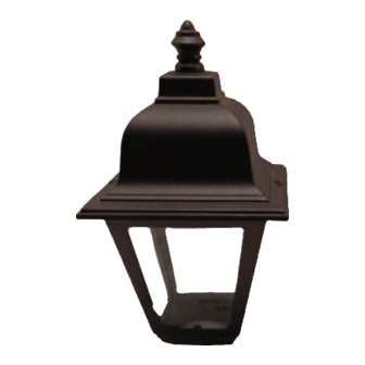
Motion Sensing
Diecast Metal Lantern
LANTERN ASSEMBLY
1. Place glass fixture onto base assembly.
2. Line up the arrow on the bottom of glass fixture
with the arrow on the fixture base (see illustration
below).
Glass Fixture
3. Gently push the two pieces together and rotate
the glass fixture 90° as shown below.
Glass Fixture
Fixture Base
Arrows
Fixture
Base
598-1270-00
Advertisement
Table of Contents

Related Manuals for HAMPTON BAY Motion Sensing Diecast Metal Lantern


Summary of Contents for HAMPTON BAY Motion Sensing Diecast Metal Lantern
- Page 1 Motion Sensing Diecast Metal Lantern FEATURES LANTERN ASSEMBLY • Automatically comes on when motion is detected. 1. Place glass fixture onto base assembly. • Automatically turns light off. 2. Line up the arrow on the bottom of glass fixture • Photocell keeps the light off during daylight with the arrow on the fixture base (see illustration hours.
-
Page 2: Installation
INSTALLATION WIRING For best performance, mount the fixture about 6 feet (1.8 m) above the ground. WARNING:Turn power off at circuit breaker 1. Remove two decorative nuts. or fuse. 2. Remove X-Bar. 3. Tighten mounting screws on X-Bar finger tight. Note: All wiring should be run in accordance with the 4. -
Page 3: Optional Wiring
Recommended Grounding Method Use a green ground “pigtail” (not provided) and twist one end together with the bare fixture wire and the box ground wire. Secure with a wire con- nector. Secure the other end of the “pigtail” with the GND screw on the X-bar. If you have metal junction box, you may not need the Black to black green “pigtail”. -
Page 4: Final Assembly
FINAL ASSEMBLY TESTING AND ADJUSTMENTS 1. Push the wires into the junction box. Make sure 1. Turn on the circuit breaker and light switch. none of the wires get pinched. 2. Slidethefixtureassemblyontothemountingscrews. Note: Sensor has a 1 minute warm up period Tighten decorative nuts removed in step 1 of Instal- before it will detect motion. -
Page 5: Operation
MODE SWITCHING SUMMARY The sensor is less sensitive to motion directly towards it and more sensitive to motion across TEST ON-TIME Switch at 1, 5, or coverage area. 10 minutes AUTO Flip light switch off Motion Motion for one second then MANUAL MODE back on* * If you get confused while switching modes, turn... -
Page 6: Troubleshooting Guide
TROUBLESHOOTING GUIDE If you experience a problem, follow this guide. SYMPTOM POSSIBLE CAUSE SOLUTION Lights will not come 1. Light switch is turned off. 1. Turn light switch on. 2. Lamp is loose or burned out. 2. Check lamp and replace if burned out. 3. - Page 7 Faroles de Metal Troquelado Detectoras de Movimiento CARACTERÍSTICAS MONTAJE DEL FAROL • Se enciende automáticamente al detectar movi- 1. Ponga el aparato de vidrio sobre el conjunto de miento. la base. • Apaga la luz automáticamente. 2. Alinee la flecha del fondo del aparato de vidrio •...
- Page 8 INSTALACION CABLEADO Para un mejor funcionamiento, instale el aparato a casi 1.8 m del suelo. ADVERTENCIA: Desconecte la energía en 1. Quite dos tuercas decorativas. el cortacircuito. 2. Quite la banda “X” de montaje. 3. Ajuste los tornillos de montaje sobre el soporte Nota: Todo el cableado debe realizarse de acuerdo X-Bar sólo con los dedos.
- Page 9 Método recomendado de conexión a tierra Use un “cable flexible” verde de a tierra (no pro- visto) y tuerza un extremo con el cable desnudo del aparato y con el cable de a tierra de la caja. Asegúrelos con un conector de cables. Asegure el otro extremo del “cable flexible”...
-
Page 10: Pruebas Y Ajustes
FINAL ASSEMBLY PRUEBAS Y AJUSTES 1. Meta los alambres en la caja de empalme. Ase- 1. Conecte el disyuntor y el interruptor de la gúrese que ninguno de estos alambres quede luz. pellizcado. 2. Deslice el conjunto del aparato sobre los torni- Nota:El detector tiene un período de calentamiento llos de montaje. -
Page 11: Operación
RESUMEN DE LAS MODALIDADES Dentro del área de cobertura el detector es menos sensible a movimientos en su dirección y más sensible DEL INTERRUPTOR a movimientos transversales. PRUEBA Mueva el interruptor de tiempo (ON-TIME) a 1, 5 ó 10 minutos Movimiento Movimiento AUTOM. -
Page 12: Especificaciones
ESPECIFICACIONES Requisitos de Energía ..120 VCA, 60 Hz Fases de Operación ..PRUEBA, AUTOMÁTICO y Alcance......Hasta 9.1 m (varía con la MANUAL temperatura circundante). Temporizador de duración Angulo de detección ..180° (del encendido).....1, 5, 10 minutos Carga Eléctrica .....Hasta 100 vatios máximo de luz incandescente Temporizador Tipo de bombilla ...Casquillo mediano, tipo “A”... -
Page 13: Caractéristiques
Lanterne en métal coulé à détecteur de mouvement CARACTÉRISTIQUES ASSEMBLAGE DE LA LANTERNE • S’allume automatiquement lors de la détection d’un 1. Placez le luminaire de verre sur le socle. mouvement. 2. Faites coïncider la flèche au bas du luminaire •... - Page 14 INSTALLATION CÂBLAGE Pour un rendement optimal, montez le luminaire à environ 1,8 m au-dessus du sol. MISE EN GARDE : Coupez l’alimentation 1. Retirez les deux écrous décoratifs. au disjoncteur ou au fusible. 2. Enlevez la barre-X. 3. Serrez à la main les vis de la croix en « X ». Note : Tous les fils doivent être installés dans un 4.
- Page 15 Méthode de mise à la terre recommandée Utilisez une «queue de cochon» verte (non four- nie) et torsadez-en une extrémité avec le fil nu du luminaire et le fil de terre de la boîte de jonction. Utilisez un serre-fils. Fixez l'autre extrémité de la «queue de cochon»...
-
Page 16: Assemblage Final
ASSEMBLAGE FINAL ESSAIS ET RÉGLAGES 1. Repoussez les fils dans la boîte de raccordement. 1. Ré-enclenchez le disjoncteur puis ouvrez Assurez-vous qu’aucun des fils n’est pincé. l’interrupteur. 2. Faites glisser le socle du luminaire sur les vis de montage. Serrez solidement sur le socle les Note : Le capteur exige 1 minute avant de dé- écrous décoratifs retirés à... - Page 17 RÉSUMÉ DU MODE DE COMMUTATION Le capteur est moins sensible aux déplacements directement vers lui; il est plus sensible aux mouve- TEST ments traversant la zone de couverture. Placer l’interrupteur ON- TIME à 1, 5 ou 10 minutes AUTO Mettre l’interrupteur Mouvement Mouvement hors circuit pendant...
-
Page 18: Fiche Technique
FICHE TECHNIQUE Courant requis .... 120 V c.a., 60 Hz Modes de Portée ......Jusqu’à 9,1 m [varie selon la fonctionnement ... ESSAI, AUTO et MANUEL température environnante]. Minuterie de Angle de détection..180° Charge électrique ..Jusqu’àdeuxampoulesincan- fonctionnement ... 1, 5 ou 10 minutes descentes, pour un maximum Minuterie d’essai .. - Page 19 NOTES/NOTAS _________ ______________________ ______________________ ______________________ ______________________ ______________________ ______________________ ______________________ ______________________ ______________________ ______________________ ______________________ ______________________ 598-1270-00...
- Page 20 NOTES/NOTAS _________ ______________________ ______________________ ______________________ ______________________ ______________________ ______________________ ______________________ ______________________ ______________________ ______________________ ______________________ ______________________ 598-1270-00...