Table of Contents
Advertisement
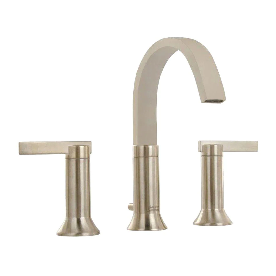
BERWICK
/ BOULEVARD
™
SPREAD LAVATORY FAUCET
with
Speed Connect™ Drain
Congratulations on purchasing your American Standard
faucet with Speed Connect drain, a feature found only on
American Standard faucets.
Speed Connect Drain*
• Fewer parts, installs in less time
• Never needs adjustment
• Guaranteed to seal properly the first time, every time.
*Your new American Standard faucet is designed to work only with the Speed Connect drain.
To ensure that your installation proceeds smoothly-please read these instructions carefully before you begin.
Recommended tools
Screwdriver
1
INSTALL FAUCET
NOTE: READ STEP #16 BEFORE INSTALLING SPOUT TO CONVERT FROM SWIVEL TO FIXED SPOUT.
Seat SEAL (1) into under side of SPOUT BASE (2).
Feed FAUCET SUPPLIES (3), MOUNTING STUD (4) and DRAIN
CABLE ASSEMBLY (8) through the mounting hole of lavatory or
mounting surface. Figure A.
From below, slide DRAIN CABLE ASSEMBLY (8) and FAUCET SUPPLIES (3)
through opening in the SPACER (9) against underside of deck. Figure B.
Note: For thick deck installaitons the SPACER (9) is not required.
From below, push GASKET (7) and RETAINING WASHER (5) onto
MOUNTING STUD (4). Secure Faucet with MOUNTING NUT (6),
pulling faucet to front of sink, so SUPPLIES (3) rests against
mounting hole. Before final tightening, make sure collar on
MOUNTING NUT (6) is seated into RETAINING WASHER (5).
Figure B.
Adjust Faucet so that it is centered. Tighten MOUNTING NUT (6)
to complete faucet mounting.
Figure B
COLLAR ON
MOUNTING NUT
Installation
Instructions
™
Channel Locks
Turn off hot and cold water
CAUTION
supplies before beginning.
7
5
6
4
7430.801
7430.821
7431.801
7431.821
Adjustable Wrench
Figure A
GROOVE
(FAUCET
BASE)
9
MOUNTING
SURFACE
1
7 4 3 0 . 8 0 1
7 4 3 1 . 8 0 1
Certified to comply with ANSI A112.18.1
M 9 6 8 6 4 0 R E V . 1 . 1
Tubing Cutter
2
4
1
3
5
8
7 4 3 0 . 8 2 1
7 4 3 1 . 8 2 1
Advertisement
Table of Contents

Subscribe to Our Youtube Channel
Related Manuals for American Standard BERWICK 7430.801


Summary of Contents for American Standard BERWICK 7430.801
- Page 1 • Never needs adjustment • Guaranteed to seal properly the first time, every time. *Your new American Standard faucet is designed to work only with the Speed Connect drain. To ensure that your installation proceeds smoothly-please read these instructions carefully before you begin.
-
Page 2: Valve Installation
VALVE INSTALLATION Place RUBBER RING (9) into DECK ADAPTER (10). Install LOCKNUT (11) and RUBBER WASHER (12) onto VALVE BODY (13). From under side of mounting surface, install VALVE BODY (13) through valve mounting holes. Threads of VALVE BODY (13) should extent at least 5/16 of a inch above mounting surface top. - Page 3 POP-UP DRAIN Remove CLEAR PLASTIC COVER (1). Remove CARDBOARD SPACER (2) from under DRAIN POP-UP (3). Tighten TAILPIECE (4) on DRAIN BODY before Fig. B. installing DRAIN BODY. REMOVE FLANGE Thread FLANGE (1) counter-clockwise and remove FLANGE (1) and FOAM GASKET (2) from drain Fig.
- Page 4 ATTACH CABLE CONNECTOR Thread CABLE CONNECTOR (1) clockwise onto DRAIN BODY CONNECTION (2) and hand tighten. Fig. A. Your new POP-UP DRAIN installation is now complete. Fig. B. Note: Tailpeice on pop-up drain is 1-1/4” O.D. Fig. B. CHECK OPERATION OF POP-UP Operate LIFT KNOB (1) to verify that STOPPER (2) opens and closes.
-
Page 5: Care Instructions
TEST INSTALLED FITTING With HANDLES (1) in OFF position, turn on WATER SUPPLIES (2) and check all connections for leaks. Remove AERATOR (3). First loosen aerator set screw with HEX WRENCH (6) supplied. Pull out AERATOR (3) with AERATOR KEY (7). Operate both HANDLES (1) to flush water lines thoroughly. -
Page 6: Troubleshooting Guide
Speed Connect™ Drain Troubleshooting Guide If sink does not hold water even though Stopper is in the “down” position: • Follow CABLE ADJUSTMENT PROCEDURE. If Stopper does not raise up fully or sink drains too slowly: • Follow CABLE ADJUSTMENT PROCEDURE. If you need to remove the Stopper: •... - Page 7 To install the stopper in “Unlocked” mode, insert the Stopper into the Drain so that the Plastic Loop is facing toward the front of the Sink and the American Standard logo is facing rear. Rotate Stopper slightly if necessary so that the Stopper slides all the way down.
- Page 8 M962837-YYY0A CROSS HANDLE ASSEMBLY M962831-YYY0A LEFT LEVER HANDLE ASSEMBLY M962830-YYY0A ESCUTCHEON KIT 918555-0070A HANDLE SCREW 617852-0070A M962492-0070A HANDLE ADAPTER 994053-0070A M918462-0070A CARTRIDGE M961634-0070A VALVE MOUNTING 024220-0070A COUPLING NUT Replace the "YYY" with A923480-0070A appropriate finish code CHROME SATIN NICKEL HOT LINE FOR HELP For toll-free information and answers to your questions, call: 1 (800) 442-1902 Weekdays 8:00 a.m.
Need help?
Do you have a question about the BERWICK 7430.801 and is the answer not in the manual?
Questions and answers