Table of Contents
Advertisement
Quick Links
Advertisement
Table of Contents

Related Manuals for Extron electronics PS 124


Summary of Contents for Extron electronics PS 124
- Page 1 Installation Manual PS 124 12 VDC, 4 Amp Power Supply 68-1714-01 Rev. A 05 09...
- Page 2 Precautions Safety Instructions • English Warning Power sources • This equipment should be operated only from the power source This symbol is intended to alert the user of important indicated on the product. This equipment is intended to be used with a main power operating and maintenance (servicing) instructions in system with a grounded (neutral) conductor.
- Page 3 • • • • • • • • • • • FCC Class B Notice This equipment has been tested and found to comply with the limits for a Class B digital device, pursuant to part 15 of the FCC Rules. These limits are designed to provide reasonable protection against harmful interference in a residential installation.
-
Page 5: Table Of Contents
Specifications ................15 Included Parts ................16 Accessories ..................16 All trademarks mentioned in this manual are the properties of their respective owners. 68-1714-01 Rev. A 05 09 PS 124 12 VDC, 4 Amp Power Supply • Table of Contents... - Page 6 Table of Contents, cont’d PS 124 12 VDC, 4 Amp Power Supply • Table of Contents...
-
Page 7: Introduction
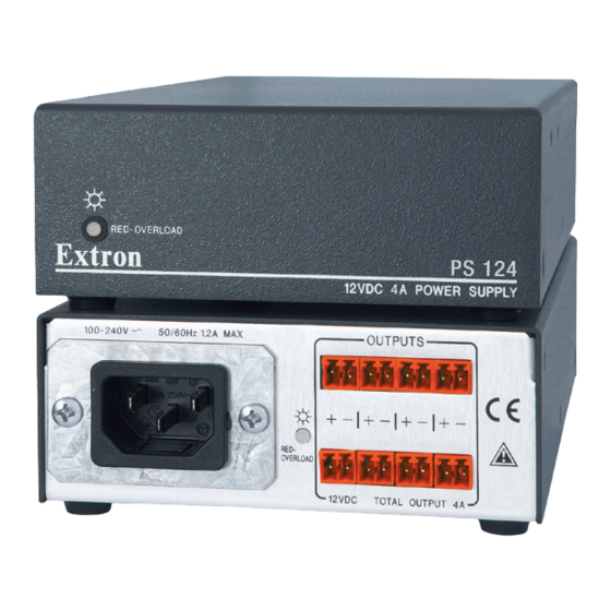
Two-tone LEDs on the front and rear panels indicate normal operation (green) and overload condition (red). The rack mountable PS 124 has a 1U high, quarter rack wide, 9" deep metal enclosure, allowing the PS 124 to take advantage of a variety of mounting options. -
Page 8: Input Power
PS 124, cont’d Input Power Apply power to the PS 124 using the supplied IEC power cord ) or by installing the optional Flexible Conduit Adapter Kit (Extron part #70-228-02) ( IEC connector/power supply — Plug the IEC cord into this connector and a 100–240 VAC source. -
Page 9: Dc Outputs
DC Outputs DC Output connectors — Connect the power cables from devices that will receive power from the PS 124 to these 3.5 mm captive screw connectors. The PS 124 supports up to eight power supply outputs. For details on limitations and how to wire these captive screw connectors, see “Output power —... -
Page 10: Connections
PS 124, cont’d Connections Input power — using the IEC power cord Use the included IEC power cord to connect the PS 124 to a 100 VAC to 240 VAC, 50-60 Hz power source. The circuit breaker used for this connection should be rated 20 amps maximum. -
Page 11: Ul Guidelines
Install the flexible conduit cable assembly to the PS 124 as follows: Remove the IEC power cord. Remove and retain the two Phillips head screws that secure the IEC plate (figure 4, below) to the PS 124 rear panel. IEC Plate 100-240 50-60Hz 1.2A MAX. - Page 12 Ground Wire Nut Figure 6 — Terminal block and IEC connector wiring Unscrew the ground wire nut on the bottom of the PS 124 enclosure and remove the ground wire. PS 124 12 VDC, 4 Amp Power Supply • Installation Manual...
- Page 13 Thread a tie wrap through the metal tab on the bottom of the PS 124, place all the wires within its cradle, and zip the tie wrap over the bundle of wires.
-
Page 14: Output Power - Wiring The Dc Output Connectors
PS 124, cont’d Output power — wiring the DC output connectors The PS 124 can supply 12 VDC to multiple devices using 3.5 mm, 2-pole captive screw connectors. The combined current draw of the connected devices must not exceed 4 amps. -
Page 15: Installing The Ps 124
UL rack mounting guidelines The following Underwriters Laboratories (UL) guidelines pertain to the installation of the PS 124 into a rack. • Elevated operating ambient temperature — If the equipment is installed in a closed or multiunit rack... -
Page 16: Rack Mounting
If feet were previously installed on the bottom of the PS 124 unit, remove them. Mount the PS 124 on the rack shelf, using two 4-40 x 3/16" screws in opposite (diagonal) corners. If necessary, mount the half rack width false front panel... -
Page 17: Under-Desk Mounting
Under-desk mounting In addition to using the PS 124 power supply on a rack or projector, it can also be mounted under furniture (such as a desk) using the MBU 125 Under-Desk Mounting Kit (part #70-077-01). To mount the PS 124 under a desk or other... -
Page 18: Above-Projector Mounting
Remove the front and rear plates from the PMK 350 (figure 11). Retain the screws to reattach the plates. If necessary, remove the feet from the bottom of the PS 124. Secure the unit to one side of the mounting tray, using two of the 4-40 x 3/16"... - Page 19 Secure the front panel to the mounting tray with four of the included #6 screws. If desired, apply one of the cover sheets to the underside of the mounting tray (figure 11). PS 124 12 VDC, 4 Amp Power Supply • Installation Manual...
- Page 20 PS 124, cont’d PS 124 12 VDC, 4 Amp Power Supply • Installation Manual...
-
Page 21: Specifications
EMI/EMC ......CE, CISPR 22 Class B, C-tick, EN55022 Class B, FCC Class B, ICES Class B, VCCI Class B Environmental ....Complies with the appropriate requirements of RoHS, WEEE PS 124 12 VDC, 4 Amp Power Supply • Installation Manual... -
Page 22: Included Parts
Warranty ......... 3 years parts and labor All nominal levels are at ±10%. Specifications are subject to change without notice. Included Parts These items are included in each order for a PS 124 power supply: Included parts Part number PS 124 Power Supply 60-1022-01 (8) 3.5 mm, 2-pole captive screw connectors... - Page 23 Extron’s Warranty Extron Electronics warrants this product against defects in materials and workmanship for a period of three years from the date of purchase. In the event of malfunction during the warranty period attributable directly to faulty workmanship and/or materials, Extron Electronics will, at its option, repair or replace said products or components, to whatever extent it shall deem necessary to restore said product to proper operating condition, provided that it is returned within the warranty period, with proof of...
- Page 24 Extron USA - West Extron USA - East Extron Europe Extron Asia Extron Japan Extron China Extron Middle East Headquarters +800.633.9876 +800.3987.6673 +800.7339.8766 +81.3.3511.7655 +400.883.1568 +971.4.2991800 +800.633.9876 Inside USA / Canada Only Inside Europe Only Inside Asia Only +81.3.3511.7656 FAX Inside China Only +971.4.2991880 FAX Inside USA / Canada Only...
Need help?
Do you have a question about the PS 124 and is the answer not in the manual?
Questions and answers