Table of Contents
Advertisement
Quick Links
Download this manual
See also:
User Manual
Advertisement
Table of Contents

Subscribe to Our Youtube Channel
Related Manuals for Supero H8QI6-F

Summary of Contents for Supero H8QI6-F
- Page 1 ® UPER H8QI6-F H8QIi-F USER’S MANUAL Revision 1.0...
- Page 2 The information in this User’s Manual has been carefully reviewed and is believed to be accurate. The vendor assumes no responsibility for any inaccuracies that may be contained in this document, makes no commitment to update or to keep current the information in this manual, or to notify any person or organization of the updates.
-
Page 3: About This Manual
This series includes the following serverboards and characteristics: Embeded IPMI Onbard SAS2 1U Board H8QI6-F H8QIi-F The H8QI6/i-F serverboard is based on the AMD® SR5690/SP5100 chipset and supports four AMD Socket F type processors with up to 128 GB of DDR2- 800/667/533 registered ECC SDRAM. - Page 4 H8QI6/i-F Serverboard User’s Manual Notes...
-
Page 5: Table Of Contents
Table of Contents Table of Contents Chapter 1 Introduction Overview ......................1 Checklist ......................1 Contacting Supermicro ..................2 H8QI6/i-F Quick Reference ................5 Chipset Overview ..................... 10 AMD SR5690/SP5100 Processor ..............10 HyperTransport Technology ................10 PC Health Monitoring ..................10 Power Confi... - Page 6 Power LED ....................17 2-10 IDE, SAS and SATA Drive Connections ............18 IDE Connectors ................... 18 SATA Ports ....................19 SAS Ports (H8QI6-F Only) ................19 2-11 Enabling SATA RAID ..................20 Serial ATA (SATA)..................... 20 Installing the OS/SATA Driver ................20 Building a Driver Diskette ................
- Page 7 Table of Contents Chapter 3 Troubleshooting Troubleshooting Procedures ................1 Before Power On ....................1 No Power ......................1 No Video ......................2 Memory Errors ....................2 Losing the System’s Setup Confi guration ............2 Technical Support Procedures ................3 Frequently Asked Questions ................
- Page 8 H8QI6/i-F Serverboard User’s Manual Notes viii...
-
Page 9: Chapter 1 Introduction
Chapter 1: Introduction Chapter 1 Introduction Overview Checklist Congratulations on purchasing your computer motherboard from an acknowledged leader in the industry. Supermicro boards are designed with the utmost attention to detail to provide you with the highest standards in quality and performance. Please check that the following items have all been included with your motherboard. -
Page 10: Contacting Supermicro
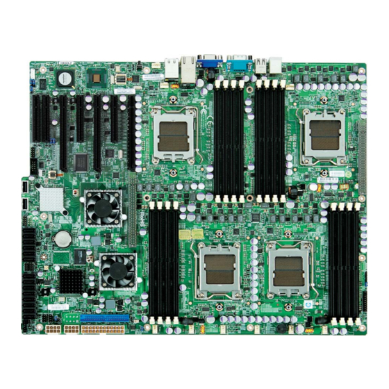
H8QI6/i-F Serverboard User’s Manual Contacting Supermicro Headquarters Address: Super Micro Computer, Inc. 980 Rock Ave. San Jose, CA 95131 U.S.A. Tel: +1 (408) 503-8000 Fax: +1 (408) 503-8008 Email: marketing@supermicro.com (General Information) support@supermicro.com (Technical Support) Web Site: www.supermicro.com Europe Address: Super Micro Computer B.V. - Page 11 Chapter 1: Introduction Figure 1-1. H8QI6-F Image...
- Page 12 H8QI6/i-F Serverboard User’s Manual Figure 1-2. H8QI6/i-F Motherboard Layout (not drawn to scale) COM1 FAN9 Intel 82576 FAN7-CPU4 FAN8-CPU4 CPU3 CPU4 SR5100 SR5690 SATA0 SATA1 Battery SATA2 SATA3 SATA4 SATA5 JIBTN1 CPU1 CPU2 SR5690 SAS0 2008 SAS1 SAS2 SAS2 SAS3 SAS4 SAS5 DP5004...
-
Page 13: H8Qi6/I-F Quick Reference
Chapter 1: Introduction H8QI6/i-F Quick Reference Jumper Description Default Setting JBT1 CMOS Clear (See Section 2-7) JCF1 Compact Flash Master/Slave Closed (Master) C1/JI C to PCI-E Slot Enable/Disable Both Closed (Enabled) JPG1 VGA Enable/Disable Pins 1-2 (Enabled) JPL1 LAN 1/2 Enable/Disable Pins 1-2 (Enabled) JPS1 SAS Controller Enable/Disable... - Page 14 HT Connectors (2) IDE#1 IDE Disk Drive Connector IPMI LAN Dedicated IPMI LAN Port Speaker Header Front Panel Connector JIBTN1 RAIDKey for RAID 5 SAS support (optional for H8QI6-F) Chassis Intrusion Header JOH1 Overheat Warning Header JPI2C1 Power I C Header JPW1...
-
Page 15: Motherboard Features
Chapter 1: Introduction Motherboard Features • Quad AMD Opteron 8000 series (Socket F type) processors Note: Support for 837x, 838x, 839x and 84xx processors. Refer to our web site for details on supported processors. Note: You must install at least two processors for full functions to be supported. Memory •... - Page 16 Six (6) SATA ports supported by an on-chip SATA controller (RAID 0, 1, 10 supported) • Eight (8) SAS ports supported by an LSI 2008 SAS2 controller (RAID 0, 1, 10 supported; Raid 5 Optional) (H8QI6-F only) • Two (2) Fast UART 16550 compatible serial port (one header and one port) •...
-
Page 17: System Block Diagram
Chapter 1: Introduction I/O CONN. I/O_CONN. HT Link DDR2-533/667 DDR2-533/667 1207-SOCKET #4 1207-SOCKET #3 4x DIMM 4x DIMM 16/16-1GHz HT Link DDR2-533/667 DDR2-533/667 1207-SOCKET #2 1207-SOCKET #1 4x DIMM 4x DIMM 16/16-1GHz PCIE (X4) SAS2 2008 (port 0~7) UIO SLOT PCIE X8 PCIE (x4) Intel... -
Page 18: Chipset Overview
H8QI6/i-F Serverboard User’s Manual Chipset Overview The H8QI6/i-F serverboard is based on the AMD SR5690/SP5100 chipset. This chipset functions as a Media and Communications Processor (MCP). Controllers for the system memory are integrated directly into AMD Opteron processors. AMD SR5690/SP5100 Processor The AMD SR5690/SP5100 are each a single-chip, high-performance HyperTrans- port peripheral controller. -
Page 19: Power Confi Guration Settings
Chapter 1: Introduction CPU Overheat/Fan Fail LED and Control This feature is available when the user enables the CPU overheat/Fan Fail warning function in the BIOS. This allows the user to defi ne an overheat temperature. When this temperature is exceeded or when a fan failure occurs, the Overheat/Fan Fail warning LED is triggered. -
Page 20: Power Supply
H8QI6/i-F Serverboard User’s Manual Wake-On-LAN (WOL) Wake-On-LAN is defi ned as the ability of a management application to remotely power up a computer that is powered off. Remote PC setup, up-dates and access tracking can occur after hours and on weekends so that daily LAN traffi c is kept to a minimum and users are not interrupted. - Page 21 Chapter 1: Introduction The Super I/O supports one PC-compatible printer port (SPP), Bi-directional Printer Port (BPP) , Enhanced Parallel Port (EPP) or Extended Capabilities Port (ECP). The Super I/O provides functions that comply with ACPI (Advanced Confi guration and Power Interface), which includes support of legacy and ACPI power manage- ment through a SMI or SCI function pin.
- Page 22 H8QI6/i-F Serverboard User’s Manual Notes 1-14...
-
Page 23: Chapter 2 Installation
Chapter 2: Installation Chapter 2 Installation Static-Sensitive Devices Electrostatic Discharge (ESD) can damage electronic com ponents. To prevent dam- age to your system board, it is important to handle it very carefully. The following measures are generally suffi cient to protect your equipment from ESD. Precautions •... -
Page 24: Processor And Heatsink Installation
H8QI6/i-F Serverboard User's Manual Processor and Heatsink Installation Exercise extreme caution when handling and installing the processor. Always connect the power cord last and always remove it before adding, removing or changing any hardware components. Installation Procedure Follow the procedures as listed below to install the motherboard into a chassis. Install the processor(s) and the heatsink(s). - Page 25 Chapter 2: Installation Align pin 1 of the CPU with pin 1 of the socket. Once aligned, carefully place the CPU into the socket. Do not drop the CPU on the socket, move the CPU horizontally or vertically or rub the CPU against the socket or against any pins of the socket, which may damage the CPU and/or the socket.
-
Page 26: Mounting The Motherboard Into A Chassis
H8QI6/i-F Serverboard User's Manual Mounting the Motherboard into a Chassis All motherboards have standard mounting holes to fi t different types of chassis. Make sure that the locations of all the mounting holes for both the motherboard and the chassis match. Although a chassis may have both plastic and metal mounting fasteners, metal ones are highly recommended because they ground the motherboard to the chassis. - Page 27 Chapter 2: Installation Gently press down on the memory module until it snaps into place. With two CPUs installed, repeat step 2 to populate the CPU2 DIMM slots. Always install pairs of DIMMs to both CPU DIMM slots for more effi cient operation.
-
Page 28: Pci Expansion Cards
H8QI6/i-F Serverboard User's Manual PCI Expansion Cards A riser card is used to support one standard size (full height full length) PCI expan- sion card. Installing a PCI Expansion Card Confi rm that you have the correct riser card for your chassis model and the add-on card includes a standard bracket. -
Page 29: I/O Port And Control Panel Connections
Chapter 2: Installation I/O Port and Control Panel Connections The I/O ports are color coded in conformance with the PC99 specifi cation to make setting up your system easier. See Figure 2-2 below for the colors and locations of the various I/O ports. Figure 2-2. -
Page 30: Connector Defi Nitions
H8QI6/i-F Serverboard User's Manual Connector Defi nitions ATX Power 24-pin Connector Pin Defi nitions Pin# Defi nition Pin # Defi nition Power Connectors +3.3V +3.3V A 24-pin main power supply connector(JPW1) -12V +3.3V and three 8-pin CPU PWR connectors (JPW2/JPW3/JPW4) on the motherboard. PS_ON These power connectors meet the SSI EPS 12V specifi... -
Page 31: Nic2 (Lan2) Led
Chapter 2: Installation NIC2 (LAN2) LED NIC2 LED Pin Defi nitions The LED connections for LAN2 are on pins (JF1) 9 and 10 of JF1. Attach LAN LED cables to Pin# Defi nition display network activity. See the table on the right for pin defi... -
Page 32: Universal Serial Bus Ports
H8QI6/i-F Serverboard User's Manual Universal Serial Bus Ports Universal Serial Bus Ports Pin Defi nitions (USB0/1, USB4/5) Two Universal Serial Bus ports (USB 2.0) are USB0 USB1 located beside the Keyboard and Mouse PS2 Pin # Defi nition Pin # Defi nition ports. -
Page 33: Sgpio
Chapter 2: Installation SGPIO SGPIO Header Pin Defi nitions (T-SGPIO1/TSGPIO2) The T-SGPIO1/ T-SGPIO2 (Serial General (3SGPIO1/3SGPIO2)) Purpose Input/Output) headers provide a Pin# Defi nition Pin # Defi nition bus between the SATA controller and the backpane to provide SATA enclosure man- Ground Data agement functions. -
Page 34: Chassis Intrusion
H8QI6/i-F Serverboard User's Manual Chassis Intrusion Chassis Intrusion Pin Defi nitions (JL1) A Chassis Intrusion header is located at JL1. Pin# Defi nition Attach the appropriate cable to inform you of Battery voltage a chassis intrusion. Intrusion signal Overheat LED Overheat LED Pin Defi... -
Page 35: Unit Identifi Er Button
Chapter 2: Installation Unit Identifi er Button UID Button Pin Defi nitions SW1 is a Unit Identifi er (UID) button. There Pin# Defi nition is another UID button located on the control Ground panel. When you push either UID button, Ground both Rear UID and Front Panel UID Indica- Button In... -
Page 36: Jumper Settings
H8QI6/i-F Serverboard User's Manual Jumper Settings Connector Pins Explanation of Jumpers To modify the operation of the motherboard, Jumper jumpers can be used to choose between optional settings. Jumpers create shorts be- tween two pins to change the function of the Setting connector. -
Page 37: I2C To Pci-Express Slot
Chapter 2: Installation I2C to PCI-Express Slot C to PCI-Express Slot Jumper Settings C1/JI C2 allows you to enable the I C bus (JPI C1/JPI to communicate with the PCI-Express slot. Jumper Setting Defi nition For the jumpers to work properly, please set Closed Enabled both jumpers to the same setting. -
Page 38: Lan1/2 Enable/Disable
H8QI6/i-F Serverboard User's Manual LAN1/2 Enable/Disable LAN1/2 En/Disable Jumper Settings (JPL1) Change the setting of jumper JPL1 to enable Jumper Setting Defi nition to enable or disable the LAN1 and LAN2 Pins 1-2 Enabled Ethernets ports. See the table on the right Pins 2-3 Disabled for jumper settings. -
Page 39: Onboard Indicators
Chapter 2: Installation Onboard Indicators LAN LED (Connection Speed Indicator) LED Color Defi nition LAN1/LAN2 LEDs 10 MHz The Ethernet ports (located beside the VGA Green 100 MHz port) have two LEDs. On each Gb LAN port, Amber 1 GHz one LED blinks to indicate activity while the other may be green, amber or off to indicate the speed of the connection. -
Page 40: Ide, Sas And Sata Drive Connections
H8QI6/i-F Serverboard User's Manual 2-10 IDE, SAS and SATA Drive Connections Use the following information to connect the IDE hard disk drive cables. • A red mark on a wire typically designates the location of pin 1. • The 80-wire ATA100/66 IDE hard disk drive cable that came with your system has two connectors to support two drives. -
Page 41: Sata Ports
SATA5. See the table on the right for pin Ground defi nitions. Ground Ground SAS Ports (H8QI6-F Only) SAS Ports Pin Defi nitions There are eight SAS ports included on the (SAS0 ~ SAS7) motherboard. See the table on the right for Pin# Defi... -
Page 42: Enabling Sata Raid
H8QI6/i-F Serverboard User's Manual 2-11 Enabling SATA RAID Now that the hardware is set up, you must install the operating system and the SATA RAID drivers, if you wish to use RAID with your SATA drives. The installation procedure differs depending on whether you wish to have the operating system installed on a RAID array or on a separate non-RAID drive. -
Page 43: Enabling Sata Raid In The Bios
Chapter 2: Installation Enabling SATA RAID in the BIOS Before installing the Windows Operating System, you must change some settings in BIOS. Boot up the system and hit the <Del> key to enter the BIOS Setup Utlility. After the Setup Utility loads, Use the arrow keys to move to the Exit menu. -
Page 44: Using The Dot Hill Raid Utility
H8QI6/i-F Serverboard User's Manual Using the Dot Hill RAID Utility The Dot Hill® RAID Utility program is where you can defi ne the drives you want to include in the RAID array and the mode and type of RAID. Figure 2-5. DOT-Hill RAID Utility Program Screen Installing the OS and Drivers With the Windows OS installation CD in the CD-ROM drive, restart the system. -
Page 45: Installing Drivers
Chapter 2: Installation 2-12 Installing Drivers The CD that came bundled with the system contains drivers, some of which must be installed, such as the chipset driver. After inserting this CD into your CD-ROM drive, the display shown in Figure 2-4 should appear. (If this display does not appear, click on the My Computer icon and then on the icon representing your CD-ROM drive. - Page 46 H8QI6/i-F Serverboard User's Manual Notes 2-24...
-
Page 47: Chapter 3 Troubleshooting
Chapter 3: Troubleshooting Chapter 3 Troubleshooting Troubleshooting Procedures Use the following procedures to troubleshoot your system. If you have followed all of the procedures below and still need assistance, refer to the ‘Technical Support Procedures’ and/or ‘Returning Merchandise for Service’ section(s) in this chapter. Always disconnect the AC power cord before adding, changing or installing any hardware components. -
Page 48: No Video
H8QI6/i-F Serverboard User's Manual Turn the power switch on and off to test the system. The battery on your motherboard may be old. Check to verify that it still sup- plies ~3VDC. If it does not, replace it with a new one. No Video If the power is on but you have no video, remove all the add-on cards and cables. -
Page 49: Technical Support Procedures
Chapter 3: Troubleshooting Technical Support Procedures Before contacting Technical Support, please take the following steps. Also, note that as a motherboard manufacturer, we do not sell directly to end-users, so it is best to fi rst check with your distributor or reseller for troubleshooting services. They should know of any possible problem(s) with the specifi... -
Page 50: Returning Merchandise For Service
H8QI6/i-F Serverboard User's Manual readme.txt (fl ash instructions), the afudos.exe (BIOS fl ash utility) and the BIOS image (xxx.rom) fi les. Copy these fi les to a bootable fl oppy disk, insert the disk into drive A and reboot the system. At the DOS prompt after rebooting, enter the command "fl... -
Page 51: Chapter 4 Bios
Chapter 4: BIOS Chapter 4 BIOS 4-1 Introduction This chapter describes the AMIBIOS™ Setup utility for the H8QI6/i-F serverboard. The AMI ROM BIOS is stored in a fl ash chip and can be easily upgraded using a fl oppy disk-based program. Note: Due to periodic changes to the BIOS, some settings may have been added or deleted and might not yet be recorded in this manual. -
Page 52: Main Menu
H8QI6/i-F Serverboard User’s Manual 4-2 Main Menu When you fi rst enter AMI BIOS Setup Utility, you will see the Main Menu screen. You can always return to the Main Menu by selecting the Main tab on the top of the screen with the arrow keys. - Page 53 Chapter 4: BIOS Secure Virtual Machine Mode This setting is used to Enable or Disable SVM. Power Now This setting is used to Enable or Disable the AMD Power Now feature. ACPI SRAT Table This option Enables or Disables the building of the ACPI SRAT Table. CPU Prefetching Use this setting to Enable or Disable CPU prefetching.
- Page 54 H8QI6/i-F Serverboard User’s Manual PIO Mode PIO (Programmable I/O) mode programs timing cycles between the IDE drive and the programmable IDE controller. As the PIO mode increases, the cycle time decreases. The options are Auto, 0, 1, 2, 3, and 4. Select Auto to allow BIOS to auto detect the PIO mode.
- Page 55 Chapter 4: BIOS ATA(PI) 80Pin Cable Detection This option selects the mechanism used for detecting the installation of an 80-pin ATA(PI) cable. Options include Host & Device, Host or Device. Floppy Confi guration Floppy A Use this option to select the type of fl oppy drive connected to the system for the Floppy A.
- Page 56 H8QI6/i-F Serverboard User’s Manual PCI IDE Busmaster Use this setting to Enable or Disable BIOS enabled uses of PCI Busmastering for reading or writing to IDE drives. Offboard PCI/ISA IDE Card Some PCI IDE cards may require this option to be set to the PCI slot number that is holding the card.
- Page 57 Chapter 4: BIOS Serial 2 Address This option specifi es the base I/O port address and Interrupt Request address of serial port 2. Select "Disabled" to prevent the serial port from accessing any system resources. When this option is set to "Disabled", the serial port physically becomes unavailable.
- Page 58 H8QI6/i-F Serverboard User’s Manual NODE0: NODE1 HT Link Width Link Width Hyper Transport runs at this width. Options include Auto, 4 Bit, 8 Bit and 16 Bit. Chipset Confi guration NorthBridge Confi guration Memory Confi guration Bank Interleaving Select Auto to automatically enable a bank-interleaving memory scheme when this function is supported by the processor.
- Page 59 Chapter 4: BIOS Power Down Enable This setting enables or disables DDR power down mode. Options are Enabled and Disabled. Power Down Mode This sets the power down mode. Options are Channel and Chip Select. ECC Confi guration ECC Mode This submenu affects the DRAM scrub rate based on its setting.
- Page 60 H8QI6/i-F Serverboard User’s Manual L2 Cache BG Scrub Allows L2 cache RAM to be corrected when idle. Options are Disabled and various times in nanoseconds and microseconds. The default is 2.56us. L3 Cache BG Scrub Allows L3 cache RAM to be corrected when idle. Options are Disabled and various times in nanoseconds and microseconds.
- Page 61 Chapter 4: BIOS SATA IDE Combined Mode This setting allows you to Enable or Disable the SATA IDE combined mode. PATA Channel Confi guration This allows you to set PATA channel confi guration. Options include SATA as Primary or SATA as secondary. Power Saving Features Use this option to Enable or Disable power down saving features in the Southbridge chipset.
- Page 62 H8QI6/i-F Serverboard User’s Manual Slot Power Limit, W Use this setting to confi gure the Slot Power Limit power. The user can adjust this value using the + and - keys. The default is 75. Compliance Mode This setting allows you to Enable or Disable the Compliance Mode. Remap Port Device Number This setting allows you remap the Port Device number.
- Page 63 Chapter 4: BIOS GPP Core Settings These submenus allow you to specify GPP core settings. Each submenu allows you to defi ne the same settings listed below. Core Confi guration This setting allows you to confi gure core confi guration. Options include Auto, 1x16 and 2x8.
- Page 64 H8QI6/i-F Serverboard User’s Manual LCLK Clock Gating in L1 Use this setting to Enable or Disable the LCLK clock gating in L1. Debug Option Peer to Peer Among GPP1/GPP2 Use this setting enable or disable Peer to Peer among GPP1/GPP2. Options include Auto, Enabled and Disabled.
- Page 65 Chapter 4: BIOS HT3 Link Power State This setting allows you to confi gure the HT3 Link power state. Options include Auto, LS0, LS1, LS2 and LS3. Unit ID Clumping Use this setting to confi gure Unit ID clumping. Options include Disabled, Auto, UnitID 2/3, UnitID B/C and UnitID 2/3 &...
- Page 66 H8QI6/i-F Serverboard User’s Manual Primary Video Controller Use this setting to specify the primary video controller boot order. Options include PCIE-GPP1-GPP2-GPP3a-PCI, PCIE-GPP2-GPP1-GPP3a-PCI, PCIE-GPP3a- GPP1-GPP2-PCI or PCI-PCIE-GPP1-GPP2-GPP3a. PCI Spread Spectrum Use this setting to Enable or Disable PCI Spread Spectrum in the system. Debug Option Memory Decod on Sec.
-
Page 67: View Bmc System Event Log
Chapter 4: BIOS Headless Mode Use this setting to Enable or Disable headless operation mode through ACPI. IPMI Confi guration This menu shows static information about the IPMI fi rmware revision and status of the BMC, as well as options for IPMI confi guration. View BMC System Event Log Pressing the Enter key will open the following settings. - Page 68 H8QI6/i-F Serverboard User’s Manual Gateway Address In the fi eld provided here enter the Gateway address in the decimal form of xxx.xxx.xxx.xxx with xxx having a value of less than 256 and in decimal form only. The current Gateway address in the BMC is shown. MPS Confi...
- Page 69 Chapter 4: BIOS Redirection After BIOS POST Options are Disable (no redirection after BIOS POST), Boot Loader (redirection during POST and during boot loader) and Always (redirection always active). Note that some OS's may not work with this set to Always. Terminal Type Selects the type of the target terminal.
-
Page 70: Boot Settings Menu
H8QI6/i-F Serverboard User’s Manual USB Mass Storage Reset Delay Use this option to set the number of seconds POST waits for the USB mass storage device after the Start Unit command. Options include 10, 20, 30 and 40 seconds. Emulation Type This sets the emulation type for USB mass storage devices. -
Page 71: Boot Device Priority
Chapter 4: BIOS Hit 'DEL' Message Display Use this option to Enable or Disable the "Press DEL to run setup" message in POST. Interrupt 19 Capture Select Enabled to allow ROMs to trap Interrupt 19. The options are Enabled and Disabled. Boot Device Priority This feature allows you to prioritize the boot sequence from the list of available devices. -
Page 72: Exit Menu
H8QI6/i-F Serverboard User’s Manual Change User Password Select this option and press <Enter> to access the sub menu, and then type in the password. Boot Sector Virus Protection This option is near the bottom of the Security Setup screen. Select "Disabled" to deactivate the Boot Sector Virus Protection. -
Page 73: Appendix A Bios Error Beep Codes
Appendix A: BIOS Error Beep Codes Appendix A BIOS Error Beep Codes During the POST (Power-On Self-Test) routines, which are performed each time the system is powered on, errors may occur. Non-fatal errors are those which, in most cases, allow the system to continue the boot-up process. - Page 74 H8QI6/i-F Serverboard User’s Manual Notes...
-
Page 75: Appendix B Bios Post Checkpoint Codes
Appendix B: BIOS POST Checkpoint Codes Appendix B BIOS POST Checkpoint Codes When AMIBIOS performs the Power On Self Test, it writes checkpoint codes to I/O port 0080h. If the computer cannot complete the boot process, diagnostic equipment can be attached to the computer to read I/O port 0080h. B-1 Uncompressed Initialization Codes The uncompressed initialization checkpoint codes are listed in order of execution: Checkpoint... -
Page 76: Bootblock Recovery Codes
H8QI6/i-F Serverboard User’s Manual B-2 Bootblock Recovery Codes The bootblock recovery checkpoint codes are listed in order of execution: Checkpoint Code Description The onboard fl oppy controller if available is initialized. Next, beginning the base 512 KB memory test. Initializing the interrupt vector table next. Initializing the DMA and Interrupt controllers next. -
Page 77: Uncompressed Initialization Codes
Appendix B: BIOS POST Checkpoint Codes B-3 Uncompressed Initialization Codes The following runtime checkpoint codes are listed in order of execution. These codes are uncompressed in F0000h shadow RAM. Checkpoint Code Description The NMI is disabled. Next, checking for a soft reset or a power on condition. The BIOS stack has been built. - Page 78 H8QI6/i-F Serverboard User’s Manual Checkpoint Code Description Interrupt vector initialization is done. Clearing the password if the POST DIAG switch is on. Any initialization before setting video mode will be done next. Initialization before setting the video mode is complete. Confi guring the monochrome mode and color mode settings next.
- Page 79 Appendix B: BIOS POST Checkpoint Codes Checkpoint Code Description The memory below 1 MB has been cleared via a soft reset. Clearing the memory above 1 MB next. The memory above 1 MB has been cleared via a soft reset. Saving the memory size next. Go- ing to checkpoint 52h next.
- Page 80 H8QI6/i-F Serverboard User’s Manual Checkpoint Code Description The password was checked. Performing any required programming before WINBIOS Setup next. The programming before WINBIOS Setup has completed. Uncompressing the WINBIOS Setup code and executing the AMIBIOS Setup or WINBIOS Setup utility next. Returned from WINBIOS Setup and cleared the screen.
- Page 81 Appendix B: BIOS POST Checkpoint Codes Checkpoint Code Description Returned from adaptor ROM at E000h control. Performing any initialization required after the E000 option ROM had control next. Initialization after E000 option ROM control has completed. Displaying the system confi guration next.
- Page 82 H8QI6/i-F Serverboard User’s Manual Notes...
Need help?
Do you have a question about the H8QI6-F and is the answer not in the manual?
Questions and answers