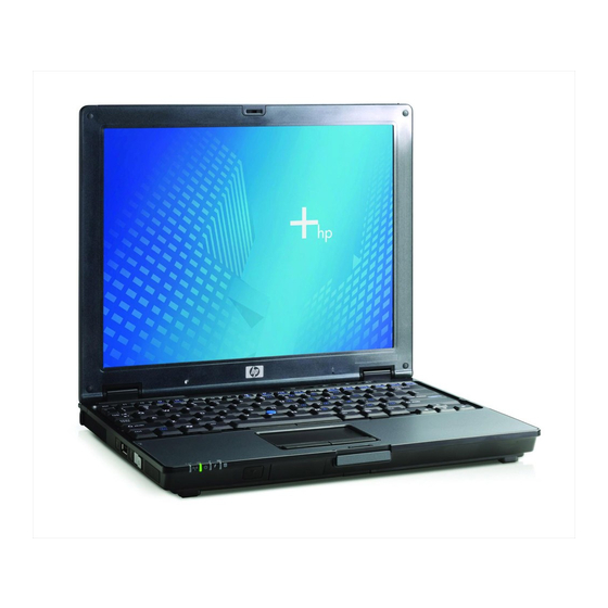
HP COMPAQ NC4200 Maintenance And Service Manual
Notebook pc
Hide thumbs
Also See for COMPAQ NC4200:
- Getting started manual (67 pages) ,
- Quickspecs (30 pages) ,
- White paper (12 pages)
Table of Contents
Advertisement
Quick Links
Maintenance and Service
Guide
HP Compaq nc4200 Notebook PC
Document Part Number: 444624-002
April 2007
This guide is a troubleshooting reference used for maintaining
and servicing the notebook. It provides comprehensive
information on identifying notebook features, components, and
spare parts; troubleshooting notebook problems; and performing
notebook disassembly procedures.
Advertisement
Chapters
Table of Contents
Troubleshooting

Related Manuals for HP COMPAQ NC4200


Summary of Contents for HP COMPAQ NC4200
- Page 1 Maintenance and Service Guide HP Compaq nc4200 Notebook PC Document Part Number: 444624-002 April 2007 This guide is a troubleshooting reference used for maintaining and servicing the notebook. It provides comprehensive information on identifying notebook features, components, and spare parts; troubleshooting notebook problems; and performing...
- Page 2 The information contained herein is subject to change without notice. The only warranties for HP products and services are set forth in the express warranty statements accompanying such products and services. Nothing herein should be construed as constituting an additional warranty. HP shall not be liable for technical or editorial errors or omissions contained herein.
- Page 3 Safety warning notice WARNING: To reduce the possibility of heat-related injuries or of Å overheating the computer, do not place the computer directly on your lap or obstruct the computer air vents. Use the computer only on a hard, flat surface. Do not allow another hard surface, such as an adjoining optional printer, or a soft surface, such as pillows or rugs or clothing, to block airflow.
-
Page 4: Table Of Contents
1 Product Description 1.1 Features ........1–2 1.2 Resetting the Notebook . - Page 5 Contents 3 Software Update and Recovery Downloading a BIOS Update ....3–3 Installing a BIOS Update ..... 3–4 Recovering the BIOS .
- Page 6 Contents 6 Removal and Replacement Procedures 6.1 Serial Number ......6–2 6.2 Disassembly Sequence Chart .
-
Page 7: Power Cord Set Requirements
Contents 7 Specifications A Connector Pin Assignments B Power Cord Set Requirements Screw Listing Index viii Maintenance and Service Guide... -
Page 8: Product Description
Product Description The HP Compaq nc4200 Notebook PC offers advanced modularity, Intel® Pentium® M and Celeron® M processors, and extensive multimedia support. HP Compaq nc4200 Notebook PC Maintenance and Service Guide 1–1... -
Page 9: Features
Product Description 1.1 Features ■ Intel Pentium M 2.13-, 2.00-, 1.86-, 1.73-, or 1.60-GHz processors, or Intel Celeron M 1.50-GHz processor, varying by notebook model ■ 12.1-inch, XGA, TFT (1024 × 768) display with over 16.8 million colors ■ 80-, 60-, or 40-GB high-capacity hard drive, varying by notebook model ■... - Page 10 ■ External 65-watt AC adapter with 3-wire power cord ■ 6-cell Li-Ion battery pack, varying by notebook model ■ Audio speaker ■ Volume up, volume mute, and volume down buttons ■ Connectors: ❏ Infrared ❏ Audio-out (headphone) ❏ Audio-in (microphone) ❏...
-
Page 11: Resetting The Notebook
Product Description 1.2 Resetting the Notebook If the notebook you are servicing has an unknown password, follow these steps to clear the password. These steps also clear CMOS: 1. Prepare the notebook for disassembly (refer to “Miscellaneous Plastics/ Hardware Kit,” information). -
Page 12: Power Management
1.3 Power Management The notebook comes with power management features that extend battery operating time and conserve power. The notebook supports the following power management features: ■ Standby ■ Hibernation ■ Setting customization by the user ■ Hotkeys for setting the level of performance ■... -
Page 13: External Components
Product Description 1.4 External Components The external components on the front of the notebook are shown below and described in Table 1-1. Front Components Item Component Wireless light Power/standby light 1–6 Table 1-1 Front Components Function On: One or more optional internal wireless devices, such as a WLAN device and/or Bluetooth®... - Page 14 Front Components (Continued) Item Component Battery light Integrated Drive Electronics (IDE) drive light Fast IrDA (select models only) Bluetooth module Display release button Maintenance and Service Guide Table 1-1 Function ■ Amber: A battery pack is charging. ■ Green: A battery pack is close to full charge capacity.
- Page 15 Product Description The external components on the right side of the notebook are shown below and described in Table 1-2. Right-Side Components 1–8 Maintenance and Service Guide...
-
Page 16: Right-Side Components
Item Component Audio-out (headphone) jack Audio-in (microphone) jack Powered USB port PC Card slot eject button PC Card slot SD Card slot Maintenance and Service Guide Table 1-2 Right-Side Components Function Connects an optional headphone or powered stereo speakers. Also connects the audio function of an audio/video device, such as a television or VCR. -
Page 17: Left-Side Components
Product Description The external components on the left side of the notebook are shown below and described in Table 1-3. Left-Side Components Item Component Security cable slot Vent 1–10 Table 1-3 Left-Side Components Function Attaches an optional security cable to the notebook. - Page 18 Left-Side Components (Continued) Item Component Wireless button (select models only) USB port Info Center button Power switch Speaker Maintenance and Service Guide Table 1-3 Function Turns the wireless functionality of the WLAN or Bluetooth device on or off, but does not establish a connection. ✎...
- Page 19 Product Description The external components on the rear panel of the notebook are shown below and described in Table 1-4. Rear Panel Components 1–12 Maintenance and Service Guide...
-
Page 20: Rear Panel Components
Item Component USB port RJ-11 (modem) jack RJ-45 (network) jack Power connector External monitor port S-Video-out jack Maintenance and Service Guide Table 1-4 Rear Panel Components Function Connects USB 1.1- and 2.0-compliant devices to the notebook using a standard USB cable. Connects a modem cable. - Page 21 Product Description The standard keyboard components of the notebook are shown below and described in Table 1-5. Standard Keyboard Components 1–14 Maintenance and Service Guide...
- Page 22 Standard Keyboard Components Item Component Function keys (12) caps lock key fn key Windows logo key Windows applications key Arrow keys Embedded numeric keypad num lock key Maintenance and Service Guide Table 1-5 Function Perform system and application tasks. When combined with the fn key, the function keys f3, f4, and f8 through f11 perform additional tasks as hotkeys.
- Page 23 Product Description The notebook top components are shown below and described in Table 1-6. Top Components 1–16 Maintenance and Service Guide...
-
Page 24: Top Components
Item Component Left and right TouchPad buttons (2) TouchPad Left and right pointing stick buttons (2) Pointing stick Vent Presentation Mode button Volume mute button Volume down button Volume up button TouchPad scroll zone Maintenance and Service Guide Table 1-6 Top Components Function Function like the left and right buttons on... - Page 25 Product Description The external components on the bottom of the notebook are shown below and described in Table 1-7. Bottom Components 1–18 Maintenance and Service Guide...
-
Page 26: Bottom Components
Item Component Base enclosure cover Docking connector Travel battery connector Vents (3) Primary battery bay Primary battery release latch Hard drive cover Expansion memory module compartment Maintenance and Service Guide Table 1-7 Bottom Components Function Covers the display cable and connector. Connects the notebook to an optional docking device. -
Page 27: Design Overview
Product Description 1.5 Design Overview This section presents a design overview of key parts and features of the notebook. Refer to to identify replacement parts, and Replacement Procedures,” The system board provides the following device connections: ■ Audio ■ Display ■... -
Page 28: Troubleshooting
WARNING: Only authorized technicians trained by HP should repair Å this equipment. All troubleshooting and repair procedures are detailed to allow only subassembly-/module-level repair. Because of the complexity of the individual boards and subassemblies, do not attempt to make repairs at the component level or modifications to any printed wiring board. -
Page 29: Accessing Computer Setup
Troubleshooting Accessing Computer Setup The information and settings in Computer Setup are accessed from the File, Security, Tools, and Advanced menus. 1. Open Computer Setup by turning on or restarting the notebook. Press displayed in the lower-left corner of the screen. ❏... -
Page 30: Selecting From The File Menu
4. To confirm the restoration, press 5. Select File > Save changes and exit, and then follow the instructions on the screen. When the computer restarts, the factory settings are restored, and any identification information you have entered is saved. Selecting from the File Menu Select System Information... -
Page 31: Selecting From The Security Menu
System IDs 2–4 Table 2-2 Security Menu To Do This Enter, change, or delete an HP Administrator password. Enter, change, or delete a power-on password. ■ Enable/Disable stringent security. ■ Enable/Disable required password on restart. Enable/disable DriveLock; change a DriveLock user or master password. -
Page 32: Selecting From The Tools Menu
Selecting from the Tools Menu Select HDD Self Test options Battery Information Memory Check Maintenance and Service Guide Table 2-3 Tools Menu To Do This Run a quick or comprehensive self-test on any hard drive in the system. View information about any battery packs in the notebook. -
Page 33: Selecting From The Advanced Menu
Troubleshooting Selecting from the Advanced Menu Select Language (or press f2) Boot options Device options 2–6 Table 2-4 Advanced Menu To Do This Change the Computer Setup language. ■ Enable/Disable MultiBoot, which sets a startup sequence that can include most bootable devices and media in the system. -
Page 34: Troubleshooting Flowcharts
2.2 Troubleshooting Flowcharts Troubleshooting Flowcharts Overview Flowchart Description “Flowchart 2.1—Initial Troubleshooting” “Flowchart 2.2—No Power, Part 1” “Flowchart 2.3—No Power, Part 2” “Flowchart 2.4—No Power, Part 3” “Flowchart 2.5—No Power, Part 4” “Flowchart 2.6—No Video, Part 1” “Flowchart 2.7—No Video, Part 2” “Flowchart 2.8—Nonfunctioning Docking Device (if applicable)”... - Page 35 Troubleshooting Troubleshooting Flowcharts Overview (Continued) Flowchart Description 2.14 “Flowchart 2.14—No OS Loading, Optical Drive” 2.15 “Flowchart 2.15—No Audio, Part 1” 2.16 “Flowchart 2.16—No Audio, Part 2” 2.17 “Flowchart 2.17—Nonfunctioning Device” 2.18 “Flowchart 2.18—Nonfunctioning Keyboard” 2.19 “Flowchart 2.19—Nonfunctioning Pointing Device” 2.20 “Flowchart 2.20—No Network/Modem Connection”...
-
Page 36: Flowchart 2.1-Initial Troubleshooting
Flowchart 2.1—Initial Troubleshooting Begin troubleshooting. Is there power? Beeps, LEDs, or error messages? Is there video? (no boot) Is the OS loading? Is there sound? Maintenance and Service Guide Go to “Flowchart 2.2—No Power, Part 1.” Check LED board, speaker connections. -
Page 37: Flowchart 2.2-No Power, Part
Troubleshooting Flowchart 2.2—No Power, Part 1 No power (power LED is off). Remove from docking device (if applicable). Power up on battery power? Power up on AC power? Power up in docking device? 1. Reseat the power cables in the docking device and at the AC outlet. -
Page 38: Flowchart 2.3-No Power, Part
Flowchart 2.3—No Power, Part 2 Continued from “Flowchart 2.2—No Power, Part 1.” Visually check for debris in battery socket and clean if necessary. Power on? Check battery by recharging it, moving it to another notebook, or replacing it. Power on? Done Maintenance and Service Guide Done... -
Page 39: Flowchart 2.4-No Power, Part
Troubleshooting Flowchart 2.4—No Power, Part 3 Continued from “Flowchart 2.3—No Power, Part 2.” Plug directly into AC outlet. Power LED Reseat AC adapter in notebook and at power source. Power on? Power outlet active? Replace power cord. Power on? 2–12 Done Done Internal or... -
Page 40: Flowchart 2.5-No Power, Part
Flowchart 2.5—No Power, Part 4 Continued from “Flowchart 2.4—No Power, Part 3.” Open notebook. Loose or damaged parts? Close notebook and retest. Power on? Done Maintenance and Service Guide Reseat loose components and boards and replace damaged items. Replace the following items (if applicable). Check notebook operation after each replacement: 1. -
Page 41: Flowchart 2.6-No Video, Part
Troubleshooting Flowchart 2.6—No Video, Part 1 No video. Docking Device Stand-alone or docking device? Stand-alone Internal or external display*? Internal External Adjust brightness. Video OK? Replace the following one at a time. Test after each replacement. Check for bent pins on cable. Video OK? Done 2–14... -
Page 42: Flowchart 2.7-No Video, Part
Flowchart 2.7—No Video, Part 2 Continued from “Flowchart 2.6—No Video, Part 1.” Remove notebook from dock- ing device, if connected. Adjust display brightness. Video OK? Check that notebook is properly seated in docking device, for bent pins on cable, and for monitor connection. Video OK? Adjust external monitor display. -
Page 43: Flowchart 2.8-Nonfunctioning Docking Device (If Applicable)
Troubleshooting Flowchart 2.8—Nonfunctioning Docking Device (if applicable) Nonfunctioning docking device. Reseat power cord in docking device and power outlet. Check voltage setting on docking device. Reset monitor cable connector at docking device. Docking device operating? Remove notebook, replace docking device. 2–16 Reinstall notebook into dock-... -
Page 44: Flowchart 2.9-No Operating System (Os) Loading
Flowchart 2.9—No Operating System (OS) Loading No OS loading.* Reseat power cord in docking device and power outlet. *NOTE: Before beginning troubleshooting, always check cable connections, cable ends, and drives for bent or damaged pins. Maintenance and Service Guide No OS loading from hard drive, go to “Flowchart 2.10—No OS Loading, Hard Drive, Part 1.”... -
Page 45: Flowchart 2.10-No Os Loading, Hard Drive
Troubleshooting Flowchart 2.10—No OS Loading, Hard Drive, Part 1 OS not loading from hard drive. Nonsystem disk message? Reseat external hard drive. OS loading? Boot from Check the Setup utility for correct booting order. Boot from hard drive? Done 2–18 Go to “Flowchart 2.11—No OS Load-... -
Page 46: Flowchart 2.1 1-No Os Loading, Hard Drive
Flowchart 2.1 1—No OS Loading, Hard Drive, Part 2 Continued from “Flowchart 2.10—No OS Loading, Hard Drive, Part 1.” 1. Replace Disc or diskette in 2. Replace drive? Remove disc or diskette and reboot. Boot from hard drive? Boot 2.13—No OS from diskette Loading, Dis- drive? -
Page 47: Flowchart 2.12-No Os Loading, Hard Drive
Troubleshooting Flowchart 2.12—No OS Loading, Hard Drive, Part 3 Continued from “Flowchart 2.11—No OS Load- ing, Hard Drive, Part 2.” System files on hard drive? Virus hard drive? Run SCANDISK and check for bad sectors. Can bad sectors be fixed? Fix bad sectors. -
Page 48: Flowchart 2.13-No Os Loading, Diskette Drive
Flowchart 2.13—No OS Loading, Diskette Drive OS not loading from diskette drive. Nonsystem disk message? Boot from another device? Diskette drive enabled in the Setup utility? Is diskette drive boot order cor- rect? Change boot priority using the Setup utility. Maintenance and Service Guide Reseat diskette drive. -
Page 49: Flowchart 2.14—No Os Loading, Optical Drive
Troubleshooting Flowchart 2.14—No OS Loading, Optical Drive No OS loading from CD-ROM or DVD-ROM drive. Boots from CD or DVD? Reseat drive. 2–22 Disc in drive? Install bootable disc. bootable disc. Done Boots from CD or DVD? Booting from another 2.17—Nonfunction- device? Reset the notebook. -
Page 50: Flowchart 2.15—No Audio, Part
Flowchart 2.15—No Audio, Part 1 No audio. Notebook in docking device (if applicable)? Go to “Flowchart 2.16—No Audio, Part 2.” 2.17—Nonfunctioning Maintenance and Service Guide Turn up audio internally or externally. Undock Replace the following docking device compo- nents one at a time, as applicable. Check audio status after each change. -
Page 51: Flowchart 2.16—No Audio, Part
Troubleshooting Flowchart 2.16—No Audio, Part 2 Continued from “Flowchart 2.15—No Audio, Part 1.” Audio driver in OS configured? Correct drivers for application? Connect to external speaker. Audio? 2–24 Reload audio drivers. Load drivers and set configuration in OS. Replace audio board and speaker connections... -
Page 52: Flowchart 2.17—Nonfunctioning Device
Flowchart 2.17—Nonfunctioning Device Unplug the nonfunctioning device from the notebook and inspect cables and plugs for bent or broken pins Clear CMOS. Reattach device. Close notebook, plug in power, and reboot. Device boots properly? Done Maintenance and Service Guide Nonfunctioning device. -
Page 53: Flowchart 2.18—Nonfunctioning Keyboard
Troubleshooting Flowchart 2.18—Nonfunctioning Keyboard Keyboard not operating prop- erly. Connect notebook to good external key- board. External device works? Reseat internal key- board connector (if applicable). Keyboard operating properly? Done 2–26 Replace system board. Replace internal keyboard or cable. Keyboard operating properly? Replace... -
Page 54: Flowchart 2.19—Nonfunctioning Pointing Device
Flowchart 2.19—Nonfunctioning Pointing Device Pointing device not operating properly. Connect notebook to good external pointing device. External device works? Reseat internal pointing device connector (if applicable). Pointing device operating properly? Done Maintenance and Service Guide Replace system board. Replace internal pointing device or cable. -
Page 55: Flowchart 2.20-No Network/Modem Connection
Troubleshooting Flowchart 2.20—No Network/Modem Connection No network or modem connec- tion. Network or modem jack or have jack acti- active? Digital line? NIC/modem drivers and recon- configured in OS? Disconnect all power from the notebook and open. Reseat NIC/modem (if applicable). 2–28 Replace jack vated. -
Page 56: Software Updates
Software Updates To stay current with the newest technology and maintain optimal performance, install the latest versions of HP software on your computer as they become available. To update HP software: 1. Identify your computer model, product category, and series or family. -
Page 57: Accessing Computer Information
Software Update and Recovery Accessing Computer Information Before you access the updates for your computer, collect the following information: ■ The product category is Notebook. ■ The product family name and series number are printed on the display bezel. ■ Model information is provided on the serial number label on the bottom of the computer. -
Page 58: Obtaining The Support Software Disc
HP Web site at Software Updates and the HP Web Site Most software on the HP Web site is packaged in a compressed file called a SoftPaq. Some BIOS updates may be packaged in a compressed file called a ROMPaq. -
Page 59: Installing A Bios Update
Software Update and Recovery To download a BIOS update: 1. Access the page on the HP Web site that provides software for your computer: ❏ Select Start > Help and Support, and then click a software update link. – or –... -
Page 60: Recovering The Bios
BIOS installation procedures vary. Follow any instructions that are displayed on the screen after the download is complete. If no instructions are displayed: 1. Open Windows Explorer by selecting Start > All Programs > Accessories > Windows Explorer. 2. In the left pane of the Windows Explorer window: a. - Page 61 5 seconds to force the notebook to turn itself off. Then repeat the BIOS recovery procedure. 3–6 on the nonfunctioning notebook keyboard until the http://www.hp.com on the notebook Maintenance and Service Guide...
-
Page 62: Illustrated Parts Catalog
Illustrated Parts Catalog This chapter provides an illustrated parts breakdown and a reference for spare part numbers. 4.1 Serial Number Location When ordering parts or requesting information, provide the notebook serial number and model number located on the bottom of the notebook. Serial Number Location Maintenance and Service Guide 4–1... -
Page 63: Notebook Major Components
Illustrated Parts Catalog 4.2 Notebook Major Components Notebook Major Components 4–2 Maintenance and Service Guide... - Page 64 Spare Parts: Notebook Major Components Item Description 12.1-inch, XGA, TFT display assembly (includes wireless antenna boards and cables) Display Hinge Kit (not illustrated) LCD rubber pad kit, with screws (not illustrated) Keyboard cover Keyboards, with pointing stick Belgium Brazil Czech Republic Denmark Europe France...
- Page 65 Illustrated Parts Catalog Notebook Major Components 4–4 Maintenance and Service Guide...
- Page 66 Spare Parts: Notebook Major Components (Continued) Item Description Rear keyboard cover Button board (includes button board cable) Top cover TouchPad TouchPad cable (not illustrated, included in the Cable Kit, spare part number 383516-001) Memory modules PC24200 1024 MB 512 MB 256 MB PC23200 1024 MB...
- Page 67 Illustrated Parts Catalog Notebook Major Components 4–6 Maintenance and Service Guide...
- Page 68 Spare Parts: Notebook Major Components (Continued) Item Description Mini PCI communications cards (Continued) 802.11a/b/g DynaStar WLAN card, for use in Japan 802.11a/b/g DynaStar WLAN card, for use in most of the world 802.11a/b/g DynaStar WLAN card, for use in the rest of the world 802.11a/b/g ATMC WLAN card, for use in Japan 802.11a/b/g ATMC WLAN card, for use in MOW...
- Page 69 Illustrated Parts Catalog Notebook Major Components 4–8 Maintenance and Service Guide...
- Page 70 Spare Parts: Notebook Major Components (Continued) Item Description Miscellaneous Plastics/Hardware Kit, includes: PC Card slot spacer Bluetooth board cover Hard drive cover Memory module compartment cover Not illustrated: Notebook feet Speaker Modem board (high-speed 56K, includes modem cable) RTC battery Base enclosure cover Infrared board (includes cable) Base enclosure...
-
Page 71: Miscellaneous Plastics/Hardware Kit
Illustrated Parts Catalog 4.3 Miscellaneous Plastics/ Hardware Kit Spare Part Number 383549-001 Item Description Hard drive cover Bluetooth cover PC Card slot space saver Memory module compartment cover (includes 2 captive screws) Notebook feet (5) 4–10 Table 4-2 Maintenance and Service Guide... -
Page 72: Miscellaneous Cable Kit
4.4 Miscellaneous Cable Kit Spare Part Number 383516-001 Description Item LED board cable RJ-11 cable TouchPad cable Bluetooth cable Maintenance and Service Guide Table 4-3 Illustrated Parts Catalog 4–1 1... -
Page 73: Miscellaneous (Not Illustrated)
Illustrated Parts Catalog 4.5 Miscellaneous (Not Illustrated) Miscellaneous Spare Part Information Description Label Kit Adjustable notebook stand Advanced Docking Station Docking Station Docking Station Miscellaneous Plastics Kit Power supply, 65 watt Keyboard point stick cap, blue Rubber domes Inverter Microphone Smart card reader LCD center hinge cap Power cords... - Page 74 Miscellaneous Spare Part Information (Continued) Description Power cords (continued) For use in: Hong Kong and the United Kingdom Israel Italy Japan The Netherlands People’s Republic of China Saudi Arabia Spain Sweden/Finland Screw Kit (includes the following screws; refer to Appendix C, “Screw Listing,” specifications and usage) ■...
-
Page 75: Sequential Part Number Listing
Illustrated Parts Catalog 4.6 Sequential Part Number Listing Sequential Part Number Listing Spare Part Number Description 337407-001 802.11a/b/g DynaStar WLAN Mini PCI communications card, for use in most of the world 337407-002 802.11a/b/g DynaStar WLAN Mini PCI communications card, for use in the rest of the world 337407-291 802.11a/b/g DynaStar WLAN Mini PCI communications card, for use in Japan... - Page 76 Sequential Part Number Listing (Continued) Spare Part Number Description 350188-AA1 Power cord for use in People’s Republic of China 350188-B71 Power cord for use in Sweden/Finland 350188-BB1 Power cord for use in Israel 370429-001 Bluetooth wireless module (includes Bluetooth module cable) 373888-001 802.11a/b/g FRLN WLAN Mini PCI communications card, for use in most of the world...
- Page 77 Illustrated Parts Catalog Sequential Part Number Listing (Continued) Spare Part Number Description 381302-001 802.11g Silverton WLAN Mini PCI communications card, for use in most of the world 381303-001 802.11g Silverton WLAN card Mini PCI communications card, for use in the rest of the world 383458-001 Keyboard with pointing stick for use in the United States 383458-021...
- Page 78 Sequential Part Number Listing (Continued) Spare Part Number Description 383458-211 Keyboard with pointing stick for use in Hungary 383458-221 Keyboard with pointing stick for use in Czech Republic 383458-231 Keyboard with pointing stick for use in Slovakia 383458-241 Keyboard with pointing stick for use in Poland 383458-251 Keyboard with pointing stick for use in Russia 383458-281...
-
Page 79: Hard Drive Cover
Illustrated Parts Catalog Sequential Part Number Listing (Continued) Spare Part Number Description 383518-001 LCD center hinge cap 383519-001 Keyboard cover 383520-001 Base enclosure cover 383522-001 Rear keyboard cover 383524-001 Rubber domes 383525-001 40-GB hard drive (5400 rpm; includes cover, frame, and connector) 383526-001 60-GB hard drive (5400 rpm;... - Page 80 Sequential Part Number Listing (Continued) Spare Part Number Description 383542-001 PC24200 512-MB memory module 383543-001 Microphone 383545-001 TPM security module 383546-001 LCD rubber pad kit with screws 383548-001 12.1-inch, XGA, TFT display assembly (includes wireless antenna boards and cables) 383549-001 Miscellaneous Plastics/Hardware Kit 383550-001 Intel Celeron M 1.50-GHz processor (includes thermal paste)
- Page 81 Illustrated Parts Catalog Sequential Part Number Listing (Continued) Spare Part Number Description 405839-001 80-GB hard drive (5400 rpm; includes cover, frame, and connector) 411337-001 Smart card reader 417947-001 LCD board 440150-001 Keyboard point stick cap, blue 4–20 Table 4-5 Maintenance and Service Guide...
-
Page 82: Removal And Replacement Preliminaries
Removal and Replacement This chapter provides essential information for proper and safe removal and replacement service. 5.1 Tools Required You will need the following tools to complete the removal and replacement procedures: ■ Magnetic screwdriver ■ Phillips P0 screwdriver ■ Torx T8 screwdriver ■... -
Page 83: Service Considerations
Removal and Replacement Preliminaries 5.2 Service Considerations The following sections include some of the considerations that you should keep in mind during disassembly and assembly procedures. ✎ As you remove each subassembly from the notebook, place the subassembly (and all accompanying screws) away from the work area to prevent damage. -
Page 84: Preventing Damage To Removable Drives
5.3 Preventing Damage to Removable Drives Removable drives are fragile components that must be handled with care. To prevent damage to the notebook, damage to a removable drive, or loss of information, observe the following precautions: ■ Before removing or inserting a hard drive, shut down the notebook. -
Page 85: Preventing Electrostatic Damage
Removal and Replacement Preliminaries 5.4 Preventing Electrostatic Damage Many electronic components are sensitive to electrostatic discharge (ESD). Circuitry design and structure determine the degree of sensitivity. Networks built into many integrated circuits provide some protection, but in many cases, the discharge contains enough power to alter device parameters or melt silicon junctions. -
Page 86: Packaging And Transporting Precautions
5.5 Packaging and Transporting Precautions Use the following grounding precautions when packaging and transporting equipment: ■ To avoid hand contact, transport products in static-safe containers, such as tubes, bags, or boxes. ■ Protect all electrostatic-sensitive parts and assemblies with conductive or approved containers or packaging. ■... -
Page 87: Workstation Precautions
Removal and Replacement Preliminaries 5.6 Workstation Precautions Use the following grounding precautions at workstations: ■ Cover the workstation with approved static-shielding material (refer to ■ Use a wrist strap connected to a properly grounded work surface and use properly grounded tools and equipment. ■... -
Page 88: Grounding Equipment And Methods
5.7 Grounding Equipment and Methods Grounding equipment must include either a wrist strap or a foot strap at a grounded workstation. ■ When seated, wear a wrist strap connected to a grounded system. Wrist straps are flexible straps with a minimum of one megohm ±10% resistance in the ground cords. -
Page 89: Typical Electrostatic Voltage Levels
Removal and Replacement Preliminaries Table 5-1 shows how humidity affects the electrostatic voltage levels generated by different activities. Typical Electrostatic Voltage Levels Event Walking across carpet Walking across vinyl floor Motions of bench worker Removing DIPS from plastic tube Removing DIPS from vinyl tray Removing DIPS from Styrofoam Removing bubble pack from PCB Packing PCBs in foam-lined box... -
Page 90: Removal And Replacement Procedures
Removal and Replacement This chapter provides removal and replacement procedures. There are 56 screws, in 10 different sizes, that may have to be removed, replaced, or loosened when servicing the notebook. Make special note of each screw and screw lock size and location during removal and replacement. -
Page 91: Serial Number
Removal and Replacement Procedures 6.1 Serial Number Report the notebook serial number to HP when requesting information or ordering spare parts. The serial number is located on the bottom of the notebook. Serial Number Location 6–2 Maintenance and Service Guide... -
Page 92: Disassembly Sequence Chart
6.2 Disassembly Sequence Chart Use the chart below to determine the section number to be referenced when removing notebook components. Disassembly Sequence Chart Section Description Preparing the notebook for disassembly Battery pack Hard drive Notebook feet Bluetooth module External memory module TPM security card Keyboard cover 6.10... -
Page 93: Speaker
Removal and Replacement Procedures Disassembly Sequence Chart (Continued) Section Description 6.13 Processor 6.14 Internal memory module 6.15 Mini PCI communications card Å To prevent an unresponsive system, replace the wireless module only with a wireless module authorized for use in the computer by the governmental agency that regulates wireless devices in your country or region. -
Page 94: Preparing The Notebook For Disassembly
6.3 Preparing the Notebook for Disassembly Before you begin any removal or installation procedures: 1. Shut down the notebook. If you are unsure whether the notebook is off or in hibernation, turn the computer on, and then shut it down through the operating system. 2. -
Page 95: Hard Drive
Removal and Replacement Procedures 6.4 Hard Drive Hard Drive Spare Part Number Information Hard drives (all 5400 rpm; include cover, frame, and connector) 80-GB 80-GB 60-GB 40-GB 1. Prepare the notebook for disassembly 2. Remove the two PM2.0×5.0 screws 1 that secure the hard drive cover to the notebook. - Page 96 Removal and Replacement Procedures 4. Loosen the PM2.5×13.0 hard drive retention screw 1. 5. Grasp the mylar tab 2 on the hard drive and slide the hard drive to the left 3 to disconnect it from the system board. 6. Remove the hard drive 4. Removing the Hard Drive Maintenance and Service Guide 6–7...
- Page 97 Removal and Replacement Procedures 7. Remove the four PM3.0×4.0 screws 1 that secure the hard drive frame to the hard drive. 8. Lift the frame straight up 2 to remove if from the hard drive. 9. Remove the hard drive connector 3. Removing the Hard Drive Frame Reverse the above procedure to reassemble and install the hard drive.
-
Page 98: Notebook Feet
Removal and Replacement Procedures 6.5 Notebook Feet The notebook feet are adhesive-backed rubber pads. The feet are included in the Miscellaneous Plastics/Hardware Kit, spare part number 383549-001. Replacing the Notebook Feet Maintenance and Service Guide 6–9... -
Page 99: Bluetooth Module
Removal and Replacement Procedures 6.6 Bluetooth Module Bluetooth Module Spare Part Number Information Bluetooth wireless module (includes Bluetooth module cable) 1. Prepare the notebook for disassembly 2. Remove the hard drive 3. Position the notebook with the front toward you. 4. - Page 100 6. Slide the Bluetooth module out of the notebook 1. 7. Disconnect the Bluetooth module cable 2 from the board. Removing the Bluetooth Module Reverse the above procedure to install the Bluetooth module. Maintenance and Service Guide Removal and Replacement Procedures 6–1 1...
-
Page 101: External Memory Module
Removal and Replacement Procedures 6.7 External Memory Module Memory Module Spare Part Number Information PC24200 1024 MB 512 MB 256 MB PC23200 1024 MB 512 MB 256 MB 1. Prepare the notebook for disassembly (refer to 2. Position the notebook with the front toward you. 6–12 383536-001 383542-001... - Page 102 3. Remove the two PM2.0×5.0 screws 1 that secure the memory module compartment cover to the notebook. 4. Lift the left side of the cover and swing it to the right 2 to remove the memory module compartment cover. ✎ The memory module compartment cover is included in the Miscellaneous Plastics/Hardware Kit, spare part number 383549-001.
- Page 103 Removal and Replacement Procedures 5. Spread the retaining tabs 1 on each side of the memory module socket to release the memory module. (The side of the module opposite the socket rises away from the notebook.) 6. Slide the module away from the socket at an angle 2. 7.
-
Page 104: Tpm Security Card
6.8 TPM Security Card TPM Security Card Spare Part Number Information TPM security module 1. Prepare the notebook for disassembly 2. Remove the memory module compartment cover (Section 3. Remove the PM1.5×3.5 screw 1 that secures the TPM security card to the notebook. 4. -
Page 105: Keyboard Cover
Removal and Replacement Procedures 6.9 Keyboard Cover Keyboard Cover Spare Part Number Information Keyboard cover 1. Prepare the notebook for disassembly 2. Position the notebook with the front toward you. 3. Remove the two T8M2.0×18.0 screws that secure the keyboard cover to the notebook. Removing the Keyboard Cover Screws 6–16 383519-001... - Page 106 4. Turn the notebook right-side up with the front toward you. 5. Open the notebook as far as possible. 6. Lift the front edge of the keyboard cover until it detaches from the notebook. Releasing the Keyboard Cover 7. Lift the keyboard cover straight up and remove it. Removing the Keyboard Cover Reverse the above procedure to install the keyboard cover.
-
Page 107: Keyboard
Removal and Replacement Procedures 6.10 Keyboard Keyboard Spare Part Number Information Keyboards, with pointing stick Belgium Brazil Czech Republic Denmark Europe France French Canada Germany Hungary Iceland Israel Italy Japan Korea Latin America The Netherlands Norway 1. Prepare the notebook for disassembly 2. - Page 108 Removal and Replacement Procedures 4. Remove the following: 1 Three T8M2.0×9.0 screws 2 One T8M2.0×5.0 screw Removing the Keyboard Screws Maintenance and Service Guide 6–19...
- Page 109 Removal and Replacement Procedures 5. Turn the notebook right-side up with the front toward you. 6. Open the notebook as far as possible. 7. Slide the keyboard back 1 until the pointing stick cable is accessible. 8. Release the zero insertion force (ZIF) connector to which the pointing stick cable is connected and disconnect the pointing stick cable 2 from the system board.
- Page 110 9. Lift the rear edge of the keyboard 1 until it disengages from the notebook. 10. Slide the keyboard forward 2 until it rests on the palm rest. 11. Release the ZIF connector to which the keyboard cable is connected and disconnect the keyboard cable 3 from the system board.
-
Page 111: Fan
Removal and Replacement Procedures 6.1 1 Fan Spare Part Number Information 1. Prepare the notebook for disassembly 2. Remove the keyboard cover 3. Release the keyboard 4. Disconnect the fan cable 1 from the system board. 5. Remove the three T8M2.0×7.5 screws 2 that secure the fan to the notebook. -
Page 112: Heat Sink
Removal and Replacement Procedures 6.12 Heat Sink Heat Sink Spare Part Number Information Heat sink (includes thermal paste) 383559-001 1. Prepare the notebook for disassembly (Section 6.3). 2. Remove the keyboard cover (Section 6.9). 3. Release the keyboard (Section 6.10). 4. - Page 113 Removal and Replacement Procedures 6. Lift the right side of the heat sink 1 to disengage it from the processor. 7. Slide the heat sink up and to the right 2 to remove it. ✎ Due to the adhesive quality of the thermal paste located between the heat sink and processor, it may be necessary to move the heat sink from side to side to detach the heat sink from the processor.
- Page 114 Removal and Replacement Procedures ✎ The thermal paste should be thoroughly cleaned from the surfaces of the heat sink 1 and processor 2 each time the heat sink is removed. Thermal paste is included with all heat sink and processor spare part kits. Thermal Paste Locations Reverse the above procedure to install the heat sink.
-
Page 115: Processor
Removal and Replacement Procedures 6.13 Processor ✎ All processor spare part kits include thermal paste. Processor Spare Part Number Information Intel Pentium M 2.13-GHz Intel Pentium M 2.00-GHz Intel Pentium M 1.86-GHz Intel Pentium M 1.73-GHz Intel Pentium M 1.60-GHz Intel Celeron M 1.50-GHz 1. - Page 116 6. Use a flat-blade screwdriver to turn the processor locking screw one-quarter turn counterclockwise 1 until you hear a click. 7. Lift the processor straight up and remove it 2. ✎ The gold triangle 3 on the processor should be aligned in the rear right corner when you install the processor.
-
Page 117: Internal Memory Module
Removal and Replacement Procedures 6.14 Internal Memory Module Memory Module Spare Part Number Information PC24200 1024 MB 512 MB 256 MB PC23200 1024 MB 512 MB 256 MB 1. Prepare the notebook for disassembly 2. Remove the keyboard cover 3. Release the keyboard 6–28 (Section (Section... - Page 118 4. Spread the retaining tabs 1 on each side of the memory module socket to release the memory module. (The side of the memory module opposite the socket rises away from the notebook.) 5. Slide the memory module away from the socket at an angle 2.
-
Page 119: Mini Pci Communications Card
Removal and Replacement Procedures 6.15 Mini PCI Communications Card Mini PCI Communications Card Spare Part Number Information 802.11g Silverton wireless local access network (WLAN) card, for use in most of the world 802.11g Silverton WLAN card, for use in the rest of the world 802.11a/b/g FRLN WLAN card, for use in Europe 802.11a/b/g FRLN WLAN card, for use in Japan 802.11a/b/g FRLN WLAN card, for use in most of the world... - Page 120 ✎ Make note of which antenna cable is attached to which antenna clip on the Mini PCI communications card before disconnecting the cables. 4. Disconnect the auxiliary and main antenna cables 1 from the Mini PCI communications card. 5. Spread the two retaining tabs 2 on each side of the Mini PCI socket to release the Mini PCI communications card.
-
Page 121: Display Assembly
Removal and Replacement Procedures 6.16 Display Assembly Display Assembly Spare Part Number Information 12.1-inch, XGA, TFT display assembly (includes wireless antenna boards and cables) Display Hinge Kit LCD rubber pad kit, with screws 1. Prepare the notebook for disassembly 2. Remove the keyboard cover 3. - Page 122 6. Remove the two T8M2.0×18.0 screws 1 that secure the display cable cover to the notebook. 7. Remove the two T8M2.0×9.0 screws 2 that secure the display assembly to the notebook. Removing the Display Assembly Screws Maintenance and Service Guide Removal and Replacement Procedures 6–33...
- Page 123 Removal and Replacement Procedures 8. Remove the base enclosure cover. Removing the Base Enclosure Cover 9. Disconnect the display cable from the system board. Disconnecting the Display Cable 6–34 Maintenance and Service Guide...
- Page 124 Removal and Replacement Procedures 10. Route the display cable through the opening between the base enclosure and the top cover. Releasing the Display Cable Maintenance and Service Guide 6–35...
- Page 125 Removal and Replacement Procedures 11. Turn the notebook right-side up with the front toward you. 12. Open the notebook as far as possible. 13. Disconnect the wireless antenna cables from the Mini PCI communications card 1. 14. Disconnect the microphone cable 2 from the system board. 15.
- Page 126 16. Route the display cable through the opening in the notebook 1. 17. Remove the two PM2.0×18.0 screws 2 that secure the display assembly to the notebook. 18. Remove the display assembly 3. Removing the Display Assembly Reverse the above procedure to install the display assembly. Maintenance and Service Guide Removal and Replacement Procedures 6–37...
-
Page 127: Button Board
Removal and Replacement Procedures 6.17 Button Board Button Board Spare Part Number Information Rear keyboard cover Button board (includes button board cable) 1. Prepare the notebook for disassembly and remove the following components: a. Keyboard cover b. Keyboard c. Display assembly 6–38 (Section 6.9) - Page 128 Removal and Replacement Procedures 2. Remove the two T8M2.0×18.0 screws 1 that secure the rear keyboard cover to the notebook. 3. Remove the rear keyboard cover 2. Removing the Rear Keyboard Cover Maintenance and Service Guide 6–39...
- Page 129 Removal and Replacement Procedures 4. Disconnect the button board cable 1 from the system board. 5. Remove the silver PM2.0×4.0 screw 2 that secures the button board to the top cover. Removing the Button Board Screw 6–40 Maintenance and Service Guide...
- Page 130 6. Lift the left side of the button board 1. 7. Slide the button board to the left 2 and remove it. Removing the Button Board Reverse the above procedure to install the button board. Maintenance and Service Guide Removal and Replacement Procedures 6–41...
-
Page 131: Top Cover
Removal and Replacement Procedures 6.18 Top Cover Top Cover Spare Part Number Information Top cover 1. Prepare the notebook for disassembly and remove the following components: a. Hard drive b. Keyboard cover c. Keyboard d. Display assembly e. Button board 6–42 (Section 6.4) - Page 132 Removal and Replacement Procedures 2. Turn the notebook upside down with the front toward you. 3. Remove the seven T8M2.0×9.0 screws that secure the top cover to the notebook. Removing the Top Cover Screws, Part 1 Maintenance and Service Guide 6–43...
- Page 133 Removal and Replacement Procedures 4. Turn the notebook right-side up with the front toward you. 5. Remove the silver PM2.0×4.0 screw that secures the top cover to the notebook. Removing the Top Cover Screw, Part 2 6–44 Maintenance and Service Guide...
- Page 134 6. Disconnect the TouchPad cable from the system board 1. 7. Lift the rear edge of the top cover 2 until it disengages from the base enclosure. 8. Lift the top cover straight up 3 and remove it. Removing the Top Cover Reverse the above procedure to install the top cover.
-
Page 135: Touchpad
Removal and Replacement Procedures 6.19 TouchPad TouchPad Spare Part Number Information TouchPad TouchPad cable (included in the Cable Kit, spare part number 383516-001) 1. Prepare the notebook for disassembly and remove the following components: a. Hard drive b. Keyboard cover c. - Page 136 Removal and Replacement Procedures 3. Remove the four PM2.0×4.0 screws that secure the TouchPad bracket to the top cover. Removing the TouchPad Bracket Screws Maintenance and Service Guide 6–47...
- Page 137 Removal and Replacement Procedures 4. Lift the right side of the TouchPad bracket 1 until it rests at an angle. 5. Slide the TouchPad bracket to the right 2 and remove it. Removing the TouchPad Bracket 6–48 Maintenance and Service Guide...
- Page 138 6. Lift the right side of the TouchPad 1 until it rests at an angle. 7. Slide the TouchPad to the right and remove it 2. Removing the TouchPad Reverse the above procedure to install the TouchPad. Maintenance and Service Guide Removal and Replacement Procedures 6–49...
-
Page 139: Speaker
Removal and Replacement Procedures 6.20 Speaker Speaker Spare Part Number Information Speaker 1. Prepare the notebook for disassembly and remove the following components: a. Hard drive b. Keyboard cover c. Keyboard d. Display assembly e. Button board f. Top cover 6–50 (Section 6.4) - Page 140 2. Disconnect the speaker cable 1 from the system board and route the cable under the infrared board cable 2. 3. Remove the two T8M2.0×5.0 screws 3 that secure the speaker to the notebook. 4. Remove the speaker 4. Removing the Speaker Reverse the above procedure to install the speaker.
-
Page 141: Infrared Board
Removal and Replacement Procedures 6.21 Infrared Board Infrared Board Spare Part Number Information Infrared board (includes cable) 1. Prepare the notebook for disassembly and remove the following components: a. Hard drive b. Keyboard cover c. Keyboard d. Display assembly e. Button board f. - Page 142 2. Release the ZIF connector to which the infrared board cable is connected and disconnect the cable 1 from the system board. 3. Remove the T8M2.0×5.0 screw 2 that secures the infrared board to the system board. 4. Remove the infrared board 3. Removing the Infrared Board Reverse the above procedure to install the infrared board .
-
Page 143: System Board
Removal and Replacement Procedures 6.22 System Board System Board Spare Part Number Information System board ✎ When replacing the system board, ensure that the following components are removed from the defective system board and installed on the replacement system board: ■... - Page 144 2. Remove the four T8M2.0×5.0 screws 1 that secure the system board to the notebook. 3. Remove the T8M2.0×7.5 screw 2 that secures the system board spacer to the notebook. 4. Remove the system board spacer 3. Removing the System Board Screws Maintenance and Service Guide Removal and Replacement Procedures 6–55...
- Page 145 Removal and Replacement Procedures 5. Lift the left side of the system board 1 until the hard drive connector 2 is clear of the base enclosure. 6. Slide the system board to the left 3 to remove it. Removing the System Board Reverse the above procedure to install the system board.
-
Page 146: Modem Board
6.23 Modem Board Modem Board Spare Part Number Information Modem board (high-speed 56K, includes modem cable) 1. Prepare the notebook for disassembly and remove the following components: a. Hard drive b. Bluetooth module c. Keyboard cover d. Keyboard e. Fan f. - Page 147 Removal and Replacement Procedures 3. Disconnect the modem cable from the two connectors 1 on the system board. 4. Remove the two PM2.0×4.0 screws 2 that secure the modem board to the system board. 5. Lift the right side of the modem board 3 to disconnect it from the system board.
-
Page 148: Rtc Battery
6.24 RTC Battery RTC Battery Spare Part Number Information RTC battery 1. Prepare the notebook for disassembly and remove the following components: a. Hard drive b. Bluetooth module c. Keyboard cover d. Keyboard e. Fan f. Heat sink g. Display assembly h. - Page 149 Removal and Replacement Procedures 3. Remove the RTC battery from the system board socket. Removing the RTC Battery Reverse the above procedure to install the RTC battery. 6–60 Maintenance and Service Guide...
-
Page 150: Specifications
This chapter provides physical and performance specifications. Dimensions Height (front to back) Width Depth Weight Input Power Operating voltage Operating current Temperature Operating (not writing to optical disc) Operating (writing to optical disc) Nonoperating Maintenance and Service Guide Specifications Table 7-1 Notebook Metric 30.2 to 31.5 mm... - Page 151 Specifications Relative humidity (noncondensing) Operating Nonoperating Maximum altitude (unpressurized) Operating (14.7 to 10.1 psia) Nonoperating (14.7 to 4.4 psia) Shock Operating Nonoperating Random Vibration Operating Nonoperating ✎ Applicable product safety standards specify thermal limits for plastic surfaces. The notebook operates well within this range of temperatures. 7–2 Table 7-1 Notebook (Continued)
- Page 152 Dimensions Height Width Diagonal Number of colors Contrast ratio Brightness Pixel resolution Pitch Format Configuration Backlight Character display Total power consumption Viewing angle Maintenance and Service Guide Table 7-2 12.1-inch, XGA, TFT Display 20.7 cm 33.1 cm 39.1 cm Up to 16.8 million 150:1 150 nits typical 0.300 ×...
-
Page 153: Hard Drives
Specifications Dimensions Height Width Weight Interface type Transfer rate Synchronous (maximum) Security Seek times (typical read, including setting) Single track Average Maximum † Logical blocks Disk rotational speed Operating temperature ✎ Certain restrictions and exclusions apply. Consult Customer Care for details. *1 GB = 1 billion bytes when referring to hard drive storage capacity. - Page 154 Primary 6-cell, Li-Ion Battery Pack Dimensions Height Width Depth Weight Energy Voltage Amp-hour capacity Watt-hour capacity Temperature Operating Nonoperating Maintenance and Service Guide Table 7-4 2.00 cm 9.40 cm 13.40 cm 0.34 kg 10.8 V 4.8 Ah 52 Wh 5°C to 45°C 0°C to 60°C Specifications 0.79 in...
-
Page 155: System Dma
Specifications Hardware DMA DMA0 DMA1* DMA2* DMA3 DMA4 DMA5* DMA6 DMA7 *PC Card controller can use DMA 1, 2, or 5. 7–6 Table 7-5 System DMA System Function Not applicable Not applicable Not applicable Not applicable Direct memory access controller Available for PC Card Not assigned Not assigned... -
Page 156: System Interrupts
Hardware IRQ IRQ0 IRQ1 IRQ2 IRQ3 IRQ4 IRQ5* IRQ6 IRQ7* IRQ8 IRQ9* IRQ10* Maintenance and Service Guide Table 7-6 System Interrupts System Function System timer Standard 101-/102-Key or Microsoft Natural Keyboard Cascaded Intel 82801DB/DBM USB2 Enhanced Host Controller—24CD COM1 Conexant AC—Link Audio Intel 82801DB/DBM SMBus Controller—24C3 Data Fax Modem with SmartCP Diskette drive... - Page 157 Specifications System Interrupts (Continued) IRQ11 IRQ12 IRQ13 IRQ14 IRQ15 *Default configuration; audio possible configurations are IRQ5, IRQ7, IRQ9, IRQ10, or none. ✎ PC Cards may assert IRQ3, IRQ4, IRQ5, IRQ7, IRQ9, IRQ10, IRQ11, or IRQ15. Either the infrared or the serial port may assert IRQ3 or IRQ4. 7–8 Table 7-6 Intel USB EHCI controller—24CD...
-
Page 158: System I/O Addresses
I/O Address (hex) 000 - 00F 010 - 01F 020 - 021 022 - 024 025 - 03F 02E - 02F 040 - 05F 044 - 05F 062 - 063 065 - 06F 070 - 071 072 - 07F 080 - 08F 090 - 091 093 - 09F 0A0 - 0A1... - Page 159 Specifications System I/O Addresses (Continued) I/O Address (hex) 0A2 - 0BF 0C0 - 0DF 0E0 - 0EF 0F0 - 0F1 0F2 - 0FF 100 - 16F 170 - 177 178 - 1EF 1F0 - 1F7 1F8 - 200 202 - 21F 220 - 22F 230 - 26D 26E - 26...
- Page 160 System I/O Addresses (Continued) I/O Address (hex) 2F0 - 2F7 2F8 - 2FF 300 - 31F 320 - 36F 370 - 377 378 - 37F 380 - 387 388 - 38B 38C - 3AF 3B0 - 3BB 3BC - 3BF 3C0 - 3DF 3E0 - 3E1 3E2 - 3E3...
-
Page 161: System Memory Map
Specifications Size Memory Address 640 KB 00000000-0009FFFF 128 KB 000A0000-000BFFFF 48 KB 000C0000-000CBFFF 160 KB 000C8000-000E7FFF 64 KB 000E8000-000FFFFF 15 MB 00100000-00FFFFFF 58 MB 01000000-047FFFFF 58 MB 04800000-07FFFFFF 2 MB 08000000-080FFFFF 4 GB 08200000-FFFEFFFF 64 KB FFFF0000-FFFFFFFF 7–12 Table 7-8 System Memory Map System Function Base memory... -
Page 162: Connector Pin Assignments
Connector Pin Assignments Signal Audio out, left channel Audio out, right channel Maintenance and Service Guide Table A-1 Audio-Out (Headphone) Signal Ground A–1... -
Page 163: Universal Serial Bus
Connector Pin Assignments Signal Audio signal in Audio signal in Signal +5 VDC Data – A–2 Table A-2 Audio-In (Microphone) Table A-3 Universal Serial Bus Signal Ground Signal Data + Ground Maintenance and Service Guide... -
Page 164: External Monitor
Signal Red analog Green analog Blue analog Not connected Ground Ground analog Ground analog Ground analog Maintenance and Service Guide Table A-4 External Monitor Signal +5 VDC Ground Monitor detect DDC 2B data Horizontal sync Vertical sync DDC 2B clock Connector Pin Assignments A–3... - Page 165 Connector Pin Assignments Signal Unused Ring A–4 Table A-5 RJ-11 (Modem) Signal Unused Unused Unused Maintenance and Service Guide...
- Page 166 Signal Transmit + Transmit – Receive + Unused Maintenance and Service Guide Table A-6 RJ-45 (Network) Signal Unused Receive – Unused Unused Connector Pin Assignments A–5...
- Page 167 Connector Pin Assignments Signal S-VHS color (C) signal Composite video signal S-VHS intensity (Y) signal S-VHS color ground A–6 Table A-7 S-Video-Out Signal TV-CD S-VHS intensity ground Composite video ground Maintenance and Service Guide...
-
Page 168: Conductor Power Cord Set
Power Cord Set Requirements 3-Conductor Power Cord Set The wide range input feature of the notebook permits it to operate from any line voltage from 100 to 120 or 220 to 240 volts AC. The power cord set included with the notebook meets the requirements for use in the country or region where the equipment is purchased. -
Page 169: General Requirements
Power Cord Set Requirements General Requirements The requirements listed below are applicable to all countries or regions. ■ The length of the power cord set must be at least 1.5 m (5.0 ft) and a maximum of 2.0 m (6.5 ft). ■... -
Page 170: Country/Region-Specific Requirements
Country/Region-Specific Requirements 3-Conductor Power Cord Set Requirements Country/Region Australia Austria Belgium Canada Denmark Finland France Germany Italy Japan ✎ NOTES: 1. The flexible cord must be <HAR> Type HO5VV-F, 3-conductor, 1.0 mm² conductor size. Power cord set fittings (appliance coupler and wall plug) must bear the certification mark of the agency responsible for evaluation in the country or region where it will be used. - Page 171 Power Cord Set Requirements 3-Conductor Power Cord Set Requirements (Continued) Country/Region The Netherlands Norway Sweden Switzerland United Kingdom United States ✎ NOTES: 1. The flexible cord must be <HAR> Type HO5VV-F, 3-conductor, 1.0 mm² conductor size. Power cord set fittings (appliance coupler and wall plug) must bear the certification mark of the agency responsible for evaluation in the country or region where it will be used.
-
Page 172: Screw Listing
Screw Listing This appendix provides specification and reference information for the screws and screw locks used in the notebook. All screws and screw locks listed in this appendix are available in the Screw Kit, spare part number 383556-001. Maintenance and Service Guide C–1... -
Page 173: Phillips Pm2.0×5.0 Screw
Screw Listing Where used: Two screws that secure the hard drive cover to the notebook (documented in Section 6.5) Two screws that secure the memory module compartment drive cover to the notebook (documented in Phillips M2.0×5.0 Screw Locations C–2 Table C-1 Phillips PM2.0×5.0 Screw Color Qty. - Page 174 Phillips PM2.0×5.0 Screw (Continued) Where used: 2 screws that secure the Bluetooth cover to the notebook (screws are captured on the cover by C clips; documented in Phillips M2.0×5.0 Screw Locations Maintenance and Service Guide Table C-1 Color Qty. Length Black 5.0 mm Section...
-
Page 175: Phillips Pm3.0×4.0 Screw
Screw Listing Phillips PM2.5×13.0 Spring-Loaded Hard Drive Retention Where used: One screw that secures the hard drive frame to the hard drive (documented Section 6.4) Where used: Four screws that secure the hard drive frame to the hard drive (documented Section 6.4) Phillips M2.5×13.0 and Phillips M3.0×4.0 Screw Locations... - Page 176 Where used: One screw that secures the TPM security card to the notebook (documented in Section 6.8) Phillips M1.5×3.5 Screw Location Maintenance and Service Guide Table C-4 Phillips PM1.5×3.5 Screw Color Qty. Silver Screw Listing Length Thread 3.5 mm 1.5 mm Head Width 4.5 mm...
- Page 177 Screw Listing Where used: 2 screws that secure the keyboard cover to the notebook (documented in Section 6.9) Torx T8M2.0×18.0 Screw Locations C–6 Table C-5 Torx T8M2.0×18.0 Screw Color Qty. Black Length Thread 18.0 mm 2.0 mm Maintenance and Service Guide Head Width 4.5 mm...
- Page 178 Torx T8M2.0×18.0 Screw (Continued) Where used: 2 screws that secure the base enclosure cover to the notebook (documented in Section 6.16) Torx T8M2.0×18.0 Screw Locations Maintenance and Service Guide Table C-5 Color Qty. Length Black 18.0 mm Screw Listing Head Thread Width 2.0 mm...
- Page 179 Screw Listing Torx T8M2.0×18.0 Screw (Continued) Where used: 2 screws that secure the display assembly to the notebook (documented in Section 6.16) Torx T8M2.0×18.0 Screw Locations C–8 Table C-5 Color Qty. Length Black 18.0 mm Maintenance and Service Guide Head Thread Width 2.0 mm...
- Page 180 Torx T8M2.0×18.0 Screw (Continued) Where used: 2 screws that secure the rear keyboard cover to the notebook (documented in Section 6.17) Torx T8M2.0×18.0 Screw Locations Maintenance and Service Guide Table C-5 Color Qty. Length Black 18.0 mm Screw Listing Head Thread Width 2.0 mm...
- Page 181 Screw Listing Where used: Three screws that secure the keyboard to the notebook (documented in Section 6.10) Two screws that secure the display assembly to the notebook (documented Section 6.16) Torx T8M2.0×9.0 Screw Locations C–10 Table C-6 Torx T8M2.0×9.0 Screw Color Qty.
- Page 182 Torx T8M2.0×9.0 Screw (Continued) Where used: 7 screws that secure the top cover to the notebook (documented in Section 6.18) Torx T8M2.0×9.0 Screw Locations Maintenance and Service Guide Table C-6 Color Qty. Length Black 9.0 mm Screw Listing Head Thread Width 2.0 mm 4.5 mm...
-
Page 183: Torx T8M2.0×5.0 Screw
Screw Listing Where used: One screw that secures the keyboard to the notebook (documented in Section 6.10) Torx T8M2.0×5.0 Screw Location C–12 Table C-7 Torx T8M2.0×5.0 Screw Color Qty. Length Black 5.0 mm Thread 2.0 mm Maintenance and Service Guide Head Width 4.5 mm... - Page 184 Torx T8M2.0×5.0 Screw (Continued) Where used: Two screws that secure the speaker to the notebook (documented in Section 6.20) One screw that secures the infrared board to the notebook (documented in Section 6.21) Torx T8M2.0×5.0 Screw Locations Maintenance and Service Guide Table C-7 Color Qty.
- Page 185 Screw Listing Torx T8M2.0×5.0 Screw (Continued) Where used: 4 screws that secure the system board to the notebook (documented in Section 6.22) Torx T8M2.0×5.0 Screw Locations C–14 Table C-7 Color Qty. Length Black 5.0 mm Maintenance and Service Guide Head Thread Width 2.0 mm...
- Page 186 Where used: 3 screws that secure the fan to the notebook (documented in Torx T8M2.0×7.5 Screw Locations Maintenance and Service Guide Table C-8 Torx T8M2.0×7.5 Screw Color Qty. Length Silver 7.5 mm Screw Listing Head Thread Width 2.0 mm 4.5 mm Section 6.11) C–15...
- Page 187 Screw Listing Torx T8M2.0×7.5 Screw (Continued) Where used: One screw that secures the system board and system board spacer to the notebook (documented in Torx T8M2.0×7.5 Screw Location C–16 Table C-8 Color Qty. Length Silver 7.5 mm Section 6.22) Maintenance and Service Guide Head Thread Width...
-
Page 188: Phillips Pm2.5×7.0 Screw
Where used: 4 screws that secure the heat sink to the notebook (documented in Section 6.12) Phillips M2.5×7.0 Screw Locations Maintenance and Service Guide Table C-9 Phillips PM2.5×7.0 Screw Color Qty. Black Screw Listing Length Thread 7.0 mm 2.5 mm Head Width 5.0 mm... -
Page 189: Phillips Pm2.0×4.0 Screw
Screw Listing Where used: One screw that secures the button board to the notebook (documented in Section 6.17) One screw that secures the top cover to the notebook (documented in Section 6.18) Phillips M2.0×4.0 Screw Locations C–18 Table C-10 Phillips PM2.0×4.0 Screw Color Qty. - Page 190 Phillips PM2.0×4.0 Screw ( Continued) Where used: 4 screws that secure the TouchPad bracket to the top cover (documented in Section 6.19) Phillips M2.0×4.0 Screw Locations Maintenance and Service Guide Table C-10 Color Qty. Length Silver 2.0 mm Screw Listing Head Thread Width...
- Page 191 Screw Listing Phillips PM2.0×4.0 Screw ( Continued) Where used: 2 screws that secure the modem board to the system board (documented in Section 6.23) Phillips M2.0×4.0 Screw Locations C–20 Table C-10 Color Qty. Length Silver 2.0 mm Maintenance and Service Guide Head Thread Width...
- Page 192 4–12 4–15 Advanced Docking Station, HP, spare part number 4–12 4–15 arrow keys 1–15 audio troubleshooting 2–23 audio-in jack location 1–9 pin assignments A–2 audio-out jack location 1–9 pin assignments A–1 base enclosure cover location 1–19...
- Page 193 Display Hinge Kit, spare part number 4–3 4–18 display release button 1–7 docking connector 1–19 docking device, troubleshooting 2–16 Docking Station, HP, spare part number 4–12 drives, preventing damage 5–3 electrostatic discharge 5–4 5–8 external monitor port, pin assignments A–3 removal 6–22...
- Page 194 Maintenance and Service Guide headphone jack, pin 2–19 2–20 heat sink 2–12 2–13 2–15 HP Advanced Docking HP Docking Station, spare part I/O address specifications 7–9 Info Center button 1–11 infrared board infrared lens 1–7 interrupt specifications 7–7 keyboard 6–6 keyboard components 1–14 keyboard cover keypad keys 1–15...
- Page 195 Index Label Kit, spare part number 4–12 4–19 LED board cable 4–11 left-side components 1–10 1–12 memory map specifications 7–12 memory module removal 6–12 spare part numbers 4–5 4–18 4–19 memory module compartment 1–19 memory module compartment cover illustrated 4–10 removal 6–13 microphone jack, pin assignments A–2...
- Page 196 PC Card slot eject button 1–9 PC Card slot space saver 4–10 plastic parts 5–2 pointing device, troubleshooting 2–27 pointing stick 1–17 pointing stick buttons 1–17 power connector 1–13 power cord set requirements B–2 spare part numbers 4–12 4–13 4–14 power management features 1–5 power supply, spare part...
- Page 197 Index notebook 7–1 system DMA 7–6 static shielding materials 5–8 S-Video-out jack location 1–13 pin assignments A–6 system board removal 6–54 spare part number 4–7 4–17 6–54 system DMA 7–6 system memory map 7–12 tools required 5–1 top components 1–16 top cover removal 6–42 spare part number 4–5...
Need help?
Do you have a question about the COMPAQ NC4200 and is the answer not in the manual?
Questions and answers