Table of Contents

Related Manuals for Koss MS2015


Summary of Contents for Koss MS2015
- Page 1 MS2015 OWNER’S MANUAL Mobile Audio System • PLL Synthesizer Stereo Radio • Digital Compact Disc Player • Automatic Memory Storing • Slide Down Detachable Panel • Preset Equalization • Remote Control...
-
Page 2: Table Of Contents
CONTENTS Installation ...........3 Playing all tracks in random ....11 Take out screw before installation..3 Selecting tracks by DIN Front-Mount (Method A) ....3 AMS/MP3 button......11 Installing the unit .......3 Display information......12 Removing the unit......4 Disc notes ...........12 DIN Rear-Mount (Method B) ....5 Remote Control Handset....13 Using the detachable front panel ..6 Specification........14... -
Page 3: Installation
INSTALLATION Notes: TAKE OUT SCREW BEFORE INSTALLATION • Choose the mounting location where Before install the unit, please remove the the unit will not interfere with the two screws. normal driving function of the driver. Take out screws before installation •... -
Page 4: Removing The Unit
INSTALLATION Sleeve Note: to install the short threading terminal L Key of the mounting bolt to the back of the unit and the other long threading terminal to the dashboard. Spring Washer Hex Nut Metal Strap Mounting Bolt R Key Plain Washer Tapping Screw 4. -
Page 5: Din Rear-Mount (Method B)
INSTALLATION 4. After removing the outer trim ring, press DIN REAR-MOUNT (Method B) OPEN/CLOSE button again to slide If your vehicle is a Nissan or a Toyota, the front panel up. Then insert both of follow these mounting instructions. the supplied keys into the slots at the Use the screw holes marked T (Toyota) left and right sides of the unit, then pull or N (Nissan) located on both sides of the... -
Page 6: Using The Detachable Front Panel
USING THE DETACHABLE FRONT PANEL To Detach the Front Panel 1. Press the OPEN/CLOSE button, the front panel will slide down. Bottom Button 2. When the panel bracket is in slide up position, insert a side of the front Open panel to its proper position and push 2. -
Page 7: Wiring Connection
WIRING CONNECTION MAIN UNIT ANTENNA CONNECTOR IGNITION SWITCH (ACC+) (BROWN) Rch RED FRONT RCA LINE OUTCABLE CHOKE MEMORY YELLOW BACK-UP (B+) Lch WHITE BLACK (GREY) GROUND (B–) Rch RED REAR RCA LINE OUT CABLE Lch WHITE POWER BLUE ANTENNA WHITE GREY FRONT Lch FRONT Lch... -
Page 8: Operation
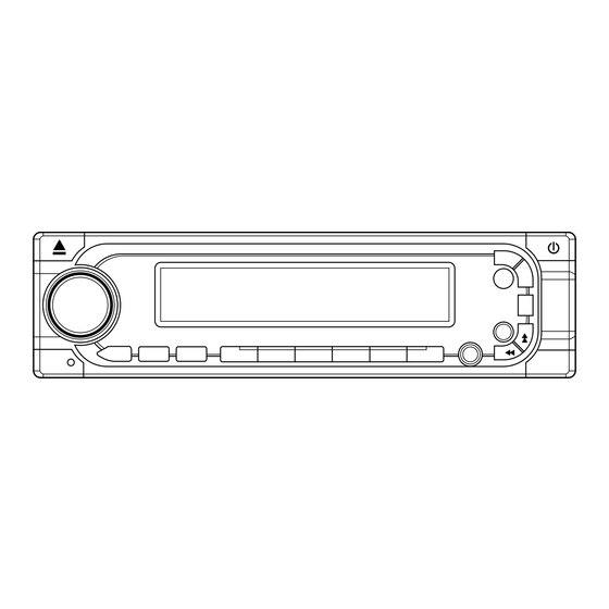
OPERATION LOCATION OF KEYS 7 10 15 11 13 19 MON Button 13. BND/LOU LOC Button 14. Preset button MUT Button 15. Display Button (DSP) 16. MANU/SKIP Search DOWN Button Disc slot 17. MANU/SKIP Search UP Button MOD Button 18. Auto Memory Store/Preset Scan OPEN/CLOSE Button ( ) Button (AMS/MP3) Liquid Crystal Display... -
Page 9: Faceplate Release
OPERATION • SWITCHING THE UNIT ON/OFF • RESET FUNCTION Switch on the unit by pressing any RESET button (12) must be activated button (except OPEN/CLOSE button with either a ball point pen or thin (7)). When system is on, press button metal object. -
Page 10: Station Storing
OPERATION stations are stored into the • PAUSING PLAYING corresponding preset number button Press PAU button (20) to pause CD positions. player. Press it again to resume play. - Program Scanning • PREVIEWING ALL TRACKS Press AMS button (18) shortly to Press SCN button (21) to play the first scan preset stations. -
Page 11: Previewing All Tracks
OPERATION • PREVIEWING ALL TRACKS buttons to list all songs under this Press SCN button (21) to play first several directory and select the title. seconds of each track on the current disc. - Press BND/LOU (ENT) button to confirm Press again to stop intro and listen to track. -
Page 12: Disc Notes
OPERATION KEY Assigned IN Searching mode (Table 1) DISC NOTE A. Notes on discs: Mode Select 1. Attempting to use non-standard shape discs (e.g. square, start, heart) may BND/LOU ENTER damage the unit. Be sure to use round shape CD discs only for this unit. A, B, C, 1 2. -
Page 13: Remote Control Handset
REMOTE CONTROL HANDSET FUNCTION KEYS & CONTROL = Power ON/OFF Button DSP (0) = Display Button (_, –, +, 0) = Select Button (Character Shift Right) = Volume Up Button [Character Select (A, B ~ 8, 9, 0)] = Volume Down Button [Character Select (A, B ~ 8, 9, 0)] BND (ENTER) = Band Select Button (Enter Button) MOD (7) -
Page 14: Specification
SPECIFICATION GENERAL Power Supply Requirements : DC 12 Volts, Negative Ground Chassis Dimensions : 178 (W) x 165 (D) x 50 (H) Tone Controls : ± 10 dB - Bass (at 100 Hz) : ± 10 dB - Treble (at 10 KHz) Maximum Output Power : 4 x 55 Watts Current Drain... -
Page 15: Trouble Shooting
TROUBLE SHOOTING Before going through the check list, check wiring connection. If any of the problems persist after check list has been made, consult your nearest service dealer. Symptom Cause Solution No power. The car ignition switch is If the power supply is not on. - Page 16 Error Code showing on display Cause Remedy ERROR 1 Mechanism problem Press “RESET” button. ERROR 2 Playback errors: Dirty disc Clean the disc and load it as instruction manual mentioned. Disc is loaded up side down Load disc with label facing up. Disc is scratched Try another disc.
- Page 17 MS2015 GUIDE D’UTILISATION Système de radio mobile • Radio stéréo à boucle de verrouillage de phase ‘PLL’ • Lecteur de disques compacts numériques • Programmation automatique des stations en mémoire • Face amovible escamotable • Égaliseur préréglé • Télécommande...
- Page 18 TABLE DES MATIÈRES Installation ...........3 Effectuer une pause de la lecture ..11 Retirer les vis avant l’installation...3 Entendre le début de chaque piste .11 Installation DIN par l’avant (méthode A) ..3 Répéter la même piste ....11 Installer l’appareil.......3 Jouer toutes les pistes dans le Retirer l’appareil.........4 désordre ..........11 Installation DIN par l’arrière (méthode B) ..5...
- Page 19 INSTALLATION Remarques : RETIRER LES VIS AVANT • Sélectionnez l’emplacement de L’INSTALLATION montage de façon à ce que l’appareil Avant d’installer l’appareil, veuillez retirer ne nuise pas aux manoeuvres du les deux vis. conducteur. • Avant de finaliser l’installation de Retirer les vis avant l’installation.
- Page 20 INSTALLATION Manchon Remarque : pour installer la borne filetée Clé de gauche courte du boulon de montage à l’arrière de l’appareil et l’autre borne filetée longue au tableau de bord. Rondelle à ressort Écrou hexagonal Sangle de métal Boulon de montage Clé...
- Page 21 INSTALLATION 4. Après avoir retiré la garniture extérieure, INSTALLATION DIN PAR L’ARRIÈRE appuyez de nouveau sur la touche (MÉTHODE B) OPEN/CLOSE pour glisser le panneau Si votre véhicule est un Nissan ou un avant vers le haut. Ensuite, insérez les Toyota, suivez ces instructions de deux clés incluses dans les fentes de montage.
- Page 22 UTILISER LA FACE AMOVIBLE Dégager la face amovible 1. Appuyez sur la touche d’ouverture et de fermeture OPEN/CLOSE et la face amovible glissera vers le bas. Bouton inférieur 2. Lorsque le support de la face est glissé vers le haut, insérez l’un des côtés de la face dans sa position appropriée et Ouvrir appuyez le côté...
- Page 23 CONNEXION DES CÂBLES UNITÉ PRINCIPALE CONNECTEUR D’ANTENNE Commutateur d’allumage ROUGE (BRUN) (ACC+) CÂBLE DE SORTIE DE LIGNE RCA AVANT Canal droit ROUGE CIRCUIT Sauvegarde de la JAUNE mémoire (B+) Canal gauche BLANC DE DÉPART (GRIS) NOIR MISE À LA CÂBLE DE SORTIE DE LIGNE RCA ARRIÈRE Canal droit ROUGE MASSE (B-) Canal gauche BLANC...
- Page 24 FONCTIONNEMENT EMPLACEMENT DES COMMANDES 7 10 15 11 13 19 Touche ‘MON’ 14. Touches des préréglages Touche de syntonisation locale ‘LOC’ 15. Touche de l’affichage ‘DSP’ Touche de sourdine ‘MUT’ 16. Touche de recherche manuelle/saut Voyant à DEL des pistes vers le bas ‘MANU/SKIP’ Fente du disque ‘...
- Page 25 FONCTIONNEMENT • METTRE L’APPAREIL EN MARCHE-ARRÊT La touche de réinitialisation ‘RESET’ (12) doit ‘ON/OFF’ être activée à l’aide de la pointe d’un stylo ou Mettez l’appareil en marche en appuyant sur d’un petit objet métallique. n’importe quelle touche (à l’exception de la Cette touche peut être utilisée dans les cas touche ‘OPEN/CLOSE’...
- Page 26 OPERATION cycle. Les six stations dont la réception est la Appuyez sur la touche ‘PAU’ (20) pour effectuer plus forte seront entrées en mémoire. Vous une pause du CD. Appuyez de nouveau sur pourrez y accéder en appuyant sur la touche cette touche pour reprendre la lecture.
- Page 27 OPERATION • CHOISIR LES PISTES EN UNE SEULE ÉTAPE qui appuie sur les touches correspondantes Pendant la lecture d’un CD, appuyez sur la énumérées au tableau 1 ci-dessous. touche (16) ou sur (17) pour vous Voici une explication de ceci : déplacer vers la piste précédente ou suivante.
- Page 28 OPERATION • RENSEIGNEMENTS RELATIFS À REMARQUES SUR LES DISQUES L’AFFICHAGE A. Remarques relatives aux disques: Appuyez sur la touche ‘DSP’. Si les données 1. Ne tentez pas de jouer des disques aux de l’étiquette ID3 TAG sont offertes, elles seront formes irrégulières (par exemple, de forme affichées en appuyant sur cette touche.
- Page 29 TÉLÉCOMMANDE TOUCHES DES FONCTIONS ET LES COMMANDES CORRESPONDANTES 1. PWR = Touche de mise en MARCHE-ARRÊT 2. DSP (0) = Touche d’affichage 3. SEL = Touche de sélection (Déplacement des caractères vers la droite) 4. VOL = Touche d’augmentation du volume (Sélection des caractères : A, B - 8, 9, 0) 5.
- Page 30 SPÉCIFICATIONS GÉNÉRALES Alimentation : 12 volts CC, masse négative Dimensions du châssis : 178 (L) ¥ 160 (P) ¥ 50 (H) Commandes de tonalité - Graves (à 100 Hz) : +/-10 dB - Aigus (à 10 KHz) : +/-10 dB Puissance de sortie maximum : 4 x 55 watts Drain de courant...
- Page 31 GUIDE DE DÉPANNAGE Avant de vérifier les points ci-dessous, vérifiez les raccords de vos fils. Si, après vérification de tous les points ci-dessous, le problème persiste encore, consultez le marchand qui vous a vendu l’appareil ou un centre de service autorisé. Solution Symptôme Cause...
- Page 32 Codes d’erreur apparaissant à l’affichage ERREUR 1 Cause Solution ERREUR 2 Problème du mécanisme Appuyez sur la touche de réinitialisation ‘RESET’. Erreurs de lecture; Le disque est sale. Nettoyez le disque et chargez-le selon les instructions du guide d’utilisation. Le disque est chargé à l’envers. Chargez le disque en vous assurant que l’étiquette soit orientée vers le haut.
Need help?
Do you have a question about the MS2015 and is the answer not in the manual?
Questions and answers