Table of Contents
Advertisement
Advertisement
Table of Contents

Related Manuals for ALLEN & HEATH MixWizard WZ4 14:4:2


Summary of Contents for ALLEN & HEATH MixWizard WZ4 14:4:2
- Page 1 MixWizard WZ 14:4:2 USER GUIDE Publication AP8666...
-
Page 2: Warranty
Limited One Year Warranty This product is warranted to be free from defects in materials or workmanship for period of one year from the date of purchase by the original owner. To ensure a high level of performance and reliability for which this equipment has been designed and manufactured, read this User Guide before operating. -
Page 3: Safety Instructions
Safety Instructions WARNING - Read the following before proceeding : CAUTION ATTENTION: RISQUE DE CHOC ELECTRIQUE - NE PAS OUVRIR Read instructions: Retain these safety and operating instructions for future reference. Adhere to all warnings printed here and on the console. Follow the operating instructions print- ed in this User Guide. -
Page 4: General Precautions
Safety Instructions Important Mains plug wiring instructions. The console is supplied with a moulded mains plug fitted to the AC mains power lead. Follow the instructions below if the mains plug has to be replaced. The wires in the mains lead are coloured in accordance with the fol- lowing code: TERMINAL WIRE COLOUR... -
Page 5: Table Of Contents
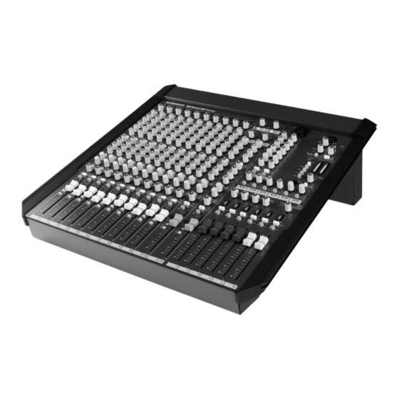
Introduction Welcome to the Allen & Heath WZ 14:4:2, the latest generation of the popular MixWizard series of compact audio mixing consoles. We have tried to keep this user guide brief and to the point. Please read it fully before starting. Included is information on installing, connecting and operating the console, panel drawings, system block diagram and technical specification. -
Page 6: Front Panel Layout
LAMP GAIN GAIN +48V (LINE) TALKBACK PHONES TRIM GAIN MATRIX - 10 10 60 40 11-12 13-14 (ST1+ST2) (ST3+ST4) OSC/NOISE 2TRK/USB GAIN GAIN TRIM PINK NOISE 2TRK 1kHz OSC TO LR 500Hz TB SELECT 35Hz GRP 1-4 AUX 1-2 LEVEL LEVEL AUX 3-4 POWER... -
Page 7: Introducing The Mixwizard
Introducing the MixWizard WZ 14:4:2 The Allen & Heath MixWizard series of consoles includes several models. This user guide de- scribes the WZ 14:4:2 4 group model. The 2 bus WZ 12:2 and WZ 16:2 consoles are de- scribed in separate publications. For further information on the MixWizard series please refer to the Allen &... -
Page 8: Installing The Console
Installing the Console Free Standing The console is supplied ready for free standing operation with its side trims fitted and connector pod positioned for rear access. If you are converting from rack to free standing then make sure the pod is correctly rotated and se- cured, and the side trims fitted as shown: 19”... -
Page 9: Connecting Power
Connecting Power FUSE CAUTION T630mA L 250V 20mm AC MAINS IN ~ RISK OF ELECTRIC SHOCK 100 - 240V~ 47-63Hz 45W MAX DO NOT OPEN CONFORMS TO ANSI/UL STD. 60065-2003 AVIS: RISQUE DE CHOC ELECTRIQUE - NE PAS OUVRIR. CERTIFICATED TO CAN/CSA STD.60065-03 CAUTION: FOR CONTINUED PROTECTION AGAINST RISK OF FIRE REPLACE FUSE WITH SAME TYPE AND RATING. -
Page 10: Connection Pin-Outs And Cables
1+3 = 12V OUTPUT INPUT XLR male socket XLR female socket 4 = 0V LAMP PIN 2 = HOT 1=ground 2=hot + 2=hot + 1=ground BALANCED BALANCED XLR male plug Female XLR plug 3=cold - 3=cold - UNBALANCED UNBALANCED INPUT / OUTPUT HEADPHONES UNBALANCED Sleeve=ground... -
Page 11: Audio Connections
Audio Connections The MixWizard uses professional grade 3 pin XLR and 1/4" TRS (3 pole) jack sockets. To ensure best perfor- mance, we recommend that you use high quality audio cables and connectors, and take time to check for relia- ble and accurate cable assembly. -
Page 12: Connector Panel Layouts
ALLEN&HEATH MixWizard WZ 14:4:2 2-TRACK 13-14 11-12 RETURN SEND INSERT INSERT INSERT INSERT INSERT INSERT INSERT INSERT INSERT INSERT INSERT INSERT INSERT LINE IN LINE IN LINE IN LINE IN LINE IN LINE IN LINE IN LINE IN LINE IN LINE IN INSERT INSERT... -
Page 13: Console Connectors
The Console connectors MIC / LINE IN The channel PAD (LINE) switch selects either the MIC XLR or the LINE TRS jack as the input source. The XLR is normalled through the TRS jack. INPUT This means that the XLR can be used for microphone or line level signals when noth- ing is plugged into the jack socket. - Page 14 GROUP (Aux), L, R, M OUT The main console mix outputs are on balanced XLR. These produce +4dBu when the meters read ‘0’. The M out- put can be switched to provide a mono sum of the post-fade L and R signals, or the PFL/AFL engineer’s wedge output.
-
Page 15: Mono Input Channel
The MONO Input Channel +48V Switches +48VDC to the channel input XLR for powering mi- crophones or DI boxes that need phantom power. The power is current +48V limited through 6k8 ohm resistors to pins 2 and 3. (LINE) GAIN WARNING: Do not connect unbalanced sources or ca- - 10 10 60 40... - Page 16 AUX SENDS These rotary controls adjust how much channel +48V signal is mixed to the aux outputs. Each of the 6 auxes has its own control. They adjust from fully off to +6dB boost. Unity gain 0dB is (LINE) marked at 3 o’clock position. Auxes 1-4, 5-6 are switched pre/post. GAIN These settings may be changed if preferred by repositioning internal - 10 10...
-
Page 17: Stereo Input Channel
The STEREO Input Channel Dual stereo inputs Each of the two stereo channels has two stereo inputs which can be used separately, mixed together or split so GAIN that one feeds the channel, the other routes direct to LR. For example, you could mix two sound effects playback devices or two reverb re- turns together into one channel. -
Page 18: Group/Aux Masters
The GROUP/AUX Masters AUX MASTERS Each aux mix has a master level control that ad- justs the output level to match external equipment, or trims the monitor, effect or other send without affecting the mix balance. Up to +10dB boost is available above the normal 0dB position. AUX AFL Press AFL to listen to the post-level aux mix in the head- phones and local monitor without affecting the main outputs. -
Page 19: Master Section
The Master Section Console Monitor Comprehensive engineer’s headphones and local monitoring is provided. Select either LR or 2-track return as the default source using the L-R / 2TRK switch. Pressing PFL or AFL elsewhere on the console automatically overrides the current monitor source with the signal from the channel or mix selection. The red PFL/AFL active indicator illuminates and the console meters display the TALKBACK PHONES... -
Page 20: Talkback, Generator And Matrix
TALKBACK, SIGNAL GENERATOR and MATRIX TALKBACK Individually assignable talkback is available to all the main outputs. Plug in a suitable cable or gooseneck microphone. A good quality dynamic or condenser vocal microphone is recommended. Note that +48V phantom power is available at the XLR as standard. If you prefer, this can be disabled by repositioning an internal jumper link. -
Page 21: Specifications
Specifications Performance Maximum output level XLR +26dBu into 600 ohms max load Jack +21dBu into 2k ohm max load Internal headroom Channels +21dB +23dB Meters 3 colour LED, quasi peak response Sensitivity 0VU = +4dBu at XLR output Master meters 12 segment -30 to +16dB Channel meters... - Page 22 Connections Mono channel XLR balanced pin 2 hot Sensitivity -60 to +10dBu TRS balanced, tip hot Sensitivity -40 to +10dBu Pad out (MIC) 2k ohm Pad in (MIC or LINE) >10k ohm, -20dB Max input level +30dBu XLR phantom power +48V, on/off Stereo channel ST1,3 TRS unbalanced >10k ohm, -16 to +20dBu...
-
Page 23: System Block Diagram
Block Diagram AUX 1-6 GRP 1-4 Allen & Heath 14:4:2 User Guide... -
Page 24: User Options
User Options The MixWizard has a versatile architecture which should satisfy most applica- REMOVE 4x M4 POZI SCREWS PER SIDE REMOVE SIDE TRIMS tions you may encounter without modification. However, the following inter- nal options provide alternative settings for those applications that may de- mand them. - Page 25 Aux pre/post insert / EQ Factory default for the mono channel pre-fade auxes is pre-insert, pre-EQ. This is MONO CH - AUX PRE/POST EQ popular with many users mixing monitors from FOH. It pre- vents the channel EQ and inserted compressors affecting the monitor mix.
- Page 26 Output balance options The aux and matrix outputs MASTER L are impedance balanced as standard operating at nominal -2dBu MASTER R and with +21dBu maximum drive. They provide similar interfer- GROUP ence rejection to electronically balanced outputs when connected to balanced equipment inputs. An electronically balanced option is available if you require nominal +4dBu and higher output drive up to +26dBu over very long cable runs.
-
Page 27: Cue Sheet
Cue Sheet 14:4:2 Copy and use this page to record your console settings ALLEN&HEATH MixWizard WZ 14:4:2 LAMP GAIN GAIN +48V +48V +48V +48V +48V +48V +48V +48V +48V +48V (LINE) (LINE) (LINE) (LINE) (LINE) (LINE) (LINE) (LINE) (LINE) (LINE) TALKBACK PHONES TRIM...
Need help?
Do you have a question about the MixWizard WZ4 14:4:2 and is the answer not in the manual?
Questions and answers