Advertisement
Advertisement

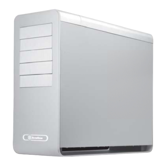
Related Manuals for SilverStone FORTRESS FT02


Summary of Contents for SilverStone FORTRESS FT02
- Page 1 FORTRESS SERIES FT02 MANUAL...
-
Page 2: Table Of Contents
Installation and system optimization guide: The following manual and guides were carefully prepared by the SilverStone engineering team to help you maximize the potential of your SilverStone product. Please keep this manual for future reference when upgrading or performing maintenance on your system. A copy of this manual can also be downloaded from our website at: http://www.silverstonetek.com... - Page 3 FT02 FORTRESS SERIES Advancing computer chassis construction and thermodynamics 4.5mm aluminum unibody frame, 0.8mm steel body SSI CEB, ATX (maximum 12” x 11”), Micro ATX SST-FT02B (black) SST-FT02S (silver) Model No. SST-FT02B-W (black + window) SST-FT02S-W (silver + window) 5.25" x 5 3.5"...
-
Page 4: Top Cover
TOP COVER LEFT SIDE PANEL 18032 FAN SWICTH x 3 PSU FILTER PS2 PSU(OPTION) 12025 FAN ATX MB(OPTION) FRONT I/O 18032 FAN GUARD x 2 SILVERSTONETEK CP05 18032 FAN x 3 18032 FAN BRACKET x 2 5.25” DRIVE BAY x 5 3.5”... -
Page 5: Installation Guide
lnstallation Guide Before you begin, please make sure that you (1) have all components collected (2) check that all components do not have compatibility problems with each other or with the case (3) if possible, assemble the components outside the case first to make sure they are working (4) keep the motherboard manual ready for reference during installation. - Page 7 lnstallation Guide Install PSU into the case as shown (two orientations are available in A or B), use screw C to secure the PSU 4.5. Route the PSU strap around the PSU and through to the corresponding hole on the motherboard tray to tighten the PSU Installieren Sie das Netzteil wie dargestellt im Gehäuse (in A oder B sind zwei Ausrichtungen verfügbar), befestigen Sie das Netzteil mit Schraube C.
- Page 8 lnstallation Guide Take the included PSU holder from Выньте из коробки с аксессуарами the accessory box and secure it прилагаемый держатель блока with screw C to the case питания и привинтите его к корпусу с помощью шурупа С. Nehmen Sie die mitgelieferte 從零件盒內取出電源支撐架, Netzteilhalterung aus dem 再用SCREW C 鎖固於機身。...
- Page 9 lnstallation Guide Push the 5.25” tool-less buttons to “unlock” С помощью отвертки удалите position,then insert an optical drive or other стальные пластины на отсеке для 5.25” device into the case and align its bezel 5,25-дюймового дисковода, затем to the front panel нажмите...
- Page 10 lnstallation Guide Remove the hard drive tray as shown Выньте корзину для жесткого диска, как показано на рисунке. Nehmen Sie den Festplatteneinschub 請依圖示將硬碟托盤取出。 wie abgebildet heraus. Retirez le support à disques durs 请依图标将硬盘托盘取出。 comme montré Quite la bandeja para discos duros 図のようにハードディスクドライブト...
- Page 11 lnstallation Guide Insert the completed hard drive tray Вставьте корзину с жестким диском в back into the case (additional CP05 корпус (приобретите дополнительные adapters can be purchased separately адаптеры CP05, чтобы получить to make all SATA hard drives возможность горячего подключения hot-swappable) жестких...
- Page 12 lnstallation Guide Use screw A to secure the 2.5” hard С помощью шурупа A закрепите drive to the bracket 2,5-дюймовый жесткий диск в кронштейне. 請依圖示用SCREW A,將2.5寸硬碟鎖固於 Sichern Sie die 2,5-Zoll-Festplatte 2.5寸硬碟架。 mit Schraube A an der Halterung. Utilisez une vis de type A pour fixer 请依图标用SCREW A,将2.5寸硬盘锁固于...
- Page 13 lnstallation Guide Insert all standoffs to corresponding Вставьте все опоры в соответствующие holes on the motherboard tray as отверстия лотка для материнской платы, required by your motherboard, then затем поместите материнскую плату на place the motherboard on the standoffs опоры и закрепите шурупом С. and secure it with screw C Stecken Sie die Abstandshalter gemäß...
- Page 14 lnstallation Guide After all wires and cables are connected После подключения всех проводов и and routed, place the side panels back кабелей верните на место боковые onto the case and secure with thumb панели корпуса и закрепите винтами с screws removed from step 2 рифленой...
-
Page 15: Connector Definition
Connector definition (1) Front panel connector installation Power switch and reset switch installation guide: LED connector installation guide: Please refer to the motherboard manuals for the motherboard’s “Front Panel Please refer to the motherboard manuals for the motherboard’s “Front Panel Connector”... -
Page 16: Front I/O Connector Guide
A continuación se detallan los pines para conectores E/S frontales, compruebe también por favor el manual de su placa base para cotejar los pines E/S frontales de la misma. Los conectores E/S de SilverStone son del tipo bloque para simplificar la instalación. - Page 17 For liquid cooling, the maximum thickness allowed for radiator is 30mm when 10.5” expansion cards are installed and 60mm when 9” cards are installed. Please remove 180mm fan filters as Снимите фильтры 180-мм вентилятора, shown then remove the four 3*8 screws как...
- Page 18 Remove 180mm fan bracket from the Выньте из корпуса кронштейн 180-мм case then unscrew the eight screws вентилятора, затем открутите двенадцать holding the fan grille to the fan шурупов, с помощью которых решетка крепится к вентилятору. 請依圖示抽出180風扇架, Entfernen Sie die Halterung des 並鬆開8顆鎖固180風扇護網的螺絲。...
- Page 19 Secure the radiator onto the fans as Закрепите радиатор поверх shown вентиляторов, как показано на рисунке. 請依圖示將水冷排鎖固於風扇上。 Befestigen Sie den Kühler wie dargestellt an den Lüftern. 请依图示将水冷排锁固于风扇上。 Fixer le radiateur sur les ventilateurs comme montré Fije el disipador a los ventiladores 図のようにラジエターをファンに固定...
- Page 20 Insert fan filters back into the fan Вставьте фильтры вентилятора обратно bracket, please make sure the filters в кронштейн вентилятора. Убедитесь, are in the correct orientation что фильтры правильно ориентированы. 請將180風扇濾網插入風扇架, Stecken Sie die Lüfterfilter wieder in 注意180風扇濾網插入時的方向性。 die Lüfterhalterung; achten Sie auf die korrekte Ausrichtung der Filter.
-
Page 21: Component Size Limitations
Le FORTRESS FT02 a été conçu pour accueillir des composants surdimensionnés, mais nous recommandons de toujours vous référer aux dimensions maximales suivantes: La Fortress FT02 fue diseñada para acomodar componentes de gran tamaño, pero de todos modos se recomienda consultar las siguientes directrices de dimensiones: В... - Page 22 EVGA’s X58 SLI Classified (10.375 inches) are wider than standard ATX motherboard specification of 9.6 inches. These boards will have no problems fitting inside the FT02. FT02’s motherboard tray also has mounting standoffs for supporting SSI-CEB dual CPU motherboards.
- Page 23 Extreme (10.6 pouces) et la EVGA’s X58 SLI Classified (10.375 pouces) sont plus larges que la spécification ATX standard de 9.6 pouces. Ces cartes se logeront sans problèmes à l'intérieur du FT02. Le support de carte mère du FT02 possède aussi des plots de montage compatible avec les cartes mères SSI-CEB double processeurs.
- Page 24 7번째 확장슬롯이 사용되지 않았을 경우, 광드라이브의 깊이는 커넥터를 포함해 193mm 까지 가능합니다. 만약 7번째 슬롯이 사용되었을 경우, 상부의 두개의 5.25” 드라이브 베이에는 180 mm 까지, 그리고, 3번째, 4번째 5번째 드라이브 베이는 약간 더 깊은 185mm 까지 광드라이브 지원이 가능합니다. FT02第1、2槽的光碟機位置只能使用深度180mm以內的光碟機。第3、4、5槽位置可有185mm的最大深度。 如果您有選用藍光光碟機,我們建議 您使用長度為185mm規格,傳輸介面為SATA的光碟機並使用90度的SATA接線。如果第7槽有裝設擴充卡,光碟機深度含接線connector不超過193mm。 FT02第1、2槽的光驱位置只能使用深度180mm以内的光驱。第3、4、5槽位置可有185mm的最大深度。 如果您有选用蓝光光驱,我们建议您使用...
-
Page 25: Top Cover Limitation
Top cover limitation 70mm The gap between I/O and top cover is 70mm Acceptable connector Unacceptable connector... -
Page 26: Recommended Cooling Device Setup & Selection
CPU ventile hacia のエアーが上方に送られるようにお勧めします。 arriba para estar en concordancia con el flujo de aire global de la FT02. Se scegliete un dissipatore a torre, assicuratevi 만약 타워 스타일의 CPU 쿨러를 che il flusso d’aria della ventola sia disposto 사용한다면, CPU 팬이... - Page 27 SilverStone bietet zudem drei Modelle der 180 mm-Lüfter zum separaten Verkauf; mit diesen können Sie Ihr System aufrüsten oder alte Lüfter ersetzen: Le FT02 possède trois ventilateurs principaux de 180mm qui peuvent être réglés avec 2 vitesses, 700 tr/min ou 1000 tr/min. Les vitesses ont été conçus pour une utilisation silencieuse ou performante.(Guide des interrupteurs des ventilateurs de 180mm“L”...
- Page 28 Le tre ventole principali da 180mm di FT02 sono regolabili secondo due velocità, 700 o 1000rpm. Regolare quindi a 700rpm se si desidera la massima silenziosità di esercizio, a 1000rpm per massimizzare le prestazioni di raffreddamento.(“L” indica lo stato di basso regime di rotazione, “H” indica lo stato...
-
Page 29: Upgrade And Maintenance
Upgrade and maintenance (1)Fan removal guide If you need to replace, clean, or upgrade the fan, please follow the steps below Please remove 180mm fan filters as Снимите фильтры 180-мм вентилятора, shown then remove the six 3*8 screws как показано на рисунке, затем открутите holding the 180mm fan bracket шесть... - Page 30 Remove 180mm fan bracket from the Выньте из корпуса кронштейн 180-мм case then unscrew the twelve screws вентилятора, затем открутите holding the fan grille to the fan двенадцать шурупов, с помощью которых решетка крепится к вентилятору. Entfernen Sie die Halterung des 180 mm-Lüfters vom Gehäuse, lösen Sie anschließend die zwölf Schrauben, die das Lüftungsgitter am Lüfter halten.
- Page 31 El diseño de presión de aire positivo de la FT02 es una configuración efectiva que reducirá la acumulación de polvo dentro de la caja. Las partículas pequeñas o micro-fibras se acumularán con el paso del tiempo en los filtros de entrada de la FT02 en lugar de en los componentes del interior de la carcasa.
- Page 32 Power supply filter removal guide: Инструкция по демонтажу фильтра Please press on the two power supply БП: нажмите на два стопора filter tabs as shown in illustration ”1”, фильтра блока питания, как показано then pull them out to remove filter from на...
- Page 33 Le FT02 est compatible avec l'installation du SST-CLEARCMOS dans une partie spéciale du boîtier, voici un exemple ci-dessous: La FT02 acepta la instalación de la SST-CLEARCMOS en cierta parte de la caja, por favor vea el siguiente ejemplo: FT02 supporta l’installazione, in una specifica zona del case, di SST-CLEARCMOS, come da esempio seguente: В...
- Page 34 SATA hot-swap You can purchase additional CP05 adapters to enable SATA hard drive hot-swap. There is already one included in the case, with four more slots available for further installation. Please note the following points if you decide to utilize the hot-swap functionality: A.
- Page 35 E’ possible acquistare separatamente adattatori CP05 per abilitare la funzione hot-swap per gli hard disk SATA. Uno è compreso negli accessori del case, ma sono presenti altri quattro slot che possono essere utilizzati con l’adattatore in oggetto. Leggere con attenzione i seguenti punti se si desidera utilizzare la funzionalità...
- Page 36 Issue date: September, 2009 G11210830...
Need help?
Do you have a question about the FORTRESS FT02 and is the answer not in the manual?
Questions and answers