Table of Contents
Advertisement
Advertisement
Table of Contents

Related Manuals for Motech LPS 305


Summary of Contents for Motech LPS 305
- Page 1 LPS 305 Linear Programmable Power Supply User’s Manual...
-
Page 2: Table Of Contents
CONTENTS GENERAL INFORMATION......................1 Introduction ..........................1 Safety Considerations ........................ 1 Options ............................3 Accessories ..........................3 Output Isolation .......................... 3 Specifications ..........................3 INSTALLATION ..........................5 Introduction ..........................5 Initial inspection .......................... 5 Location and cooling ........................5 Input power requirements ......................5 Line fuse ............................. -
Page 4: General Information
GENERAL INFORMATION Introduction This section contains a general description of your power supply as well as its performance specifications. Information about options and accessories are also provided. The TPS-3025 series has been designed and tested according to EN-61010-1, Safety requirement for Electronic Measuring Apparatus. - Page 5 Under certain conditions, dangerous voltages may exist even with power cable removed. To avoid injuries, always disconnect power, discharge circuits and remove external voltage sources before touching components. DO NOT SERVICE OR ADJUST ALONE Do not attempt internal service or adjustment unless another person, capable of rendering first aid and resuscitation, is present.
-
Page 6: Options
The output of the power supply is isolated from earth ground. Either output terminal may be grounded or the output may floated up to +/- 240 Vdc (including output voltage) from chassis ground Specifications TRIPLE OUTPUT LINEAR POWER SUPPLY UP TO 165 WATTS Model LPS 305 MAX. OUTPUT POWER 165 WATTS OUTPUT VOLTAGE Output Voltage 0 to +30V / 0 to -30V Fixed 3.3V / 5V... - Page 7 Ripple/Noise (p-p) 10mVp-p 20mVp-p Transient Response 200s Typical 100ppm / ℃ Typical Temperature Coefficient CONSTANT CURRENT CHARACTERISTICS (at rated output : 2.5A ) Line regulation (for change of AC 10% ) 15mA Typical Load regulation (for change from short to 10mA Typical full load ) Ripple/Noise rms...
-
Page 8: Installation
INSTALLATION Introduction This section contains instructions for checking and mounting your power supply and connection your power supply to AC power. The power supply generates operating magnetic which may affect the operation other instruments. If your instrument is susceptible to operating magnetic fields, position it more than three inches from the power supply. -
Page 9: Getting Started
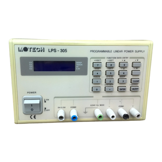
GETTING STARTED Front panel controls and output terminals Note : most soft keys have two functions. The first function of the key is function entry (i.e. + Vset, -Iset, Tracking etc.)The second function for the soft keys is data entry (ji. E. 0~9). REFER TO THE FIGURE A. - Page 10 point key. (15) Beep (3) : Beeper control key which toggle the beeper on or off. Numeric entry key for number three. (16) Enter : Enter the values on the display for the specified function and return the display to output-off mode or metering mode. (17) Clear : Used in conjunction with the numeric entry keys to clear partially set commands.
-
Page 11: Lcd Display Message
LPS - 305 +VSET +ISET INDEP TRACK -VSET -ISET 3.3V TRACK BEEP ±OUTPUT POWER ±240 Vc MAX 5V/3.3V COM2 COM1 23 11 FIGURE A LCD display message REFER TO THE FIGURE B. INDEP ALL OUTPUT OFF TRACK 20.00V -15.00V 3.3V FIGURE B... -
Page 12: Rear Panel
STATUS ANNUNCIATORS Position 1: Indicator of CV mode or CC mode of + output (positive). It will flash when the output is enabled. Position 2: Indicator of CV mode or CC mode of - output (negative). It will flash when the output is enabled. Position 3: Indicator of the independent mode or tracking mode. -
Page 13: Operation
OPERATION Initial conditions When AC voltage is applied, the power supply undergoes a self-test and disables all outputs by default. The display will show an “ALL OUTPUT OFF “ message along with the + Vset and – Vest values as shown in Figure 4.1. -
Page 14: Enabling/Disabling The Output
when the selected output is disabled. Enabling/Disabling the output The selected output channel can be turned on and off from the front panel. The output on/off key toggles both the +output and –output on and off simultaneously. The “.” key toggles the 5V or 3.3V output on and off. -
Page 15: Calibration
CALIBRATION Calibration steps: Equipment needed for calibration: DMM, such as Fluke model 45 or HP 34401A. Step 1: Simultaneously press the “8” and the “ -▼ ” keys on the Keypad and the following message will Appear on the LCD: INDEP Lo=09.487 TRACK... - Page 16 Step 4: Measure the DC current from +out terminals (+ and COM1) with the DMM and keyin the value (i.e. if the DMM shows 0.728A, then keyin 0.728 ) followed by the “ENTER” key. The following message will then appear on the LCD: INDEP Hi=2.491 TRACK...
- Page 17 3.3V Step 9: Repeat step 8. Keyin the measured value (i.e. if the DMM shows 2.418A, then keyin 2.418) followed by the “ENTER” key. The following message will then appear on the LCD: INDEP MOTECH LPS 305 TRACK Version 1.17 3.3V...
-
Page 18: User Maintenance/Service
ERROR#2 will disappear as well as the beep sound. EEPROM Reset Procedure for LPS 305: Press the -Iset(5) key and the +▼ key simultaneously. Using the RS-232-C Serial Interface This section describes hoe to set up the RS-232-C interface for remote control. - Page 19 Command Description Example 0=+/- output off OUT0 1=+/- output on OUT1 TRACK 0= independent TRACK0 1= tracking from ch1 TRACK1 2= tracking from ch2 TRACK2 STATUS Working status(see note7) STATUS CALI 0=Reset CALI0 1=begin calibration CALI1 2=input calibration parameter CALI2 9.574 MODEL Display model no.
- Page 20 0:beeper function off 1:beeper function on Bit 10: 0:CC output compensated off 1:CC output compensated on...
- Page 22 ZOM-305MI-1B...
Need help?
Do you have a question about the LPS 305 and is the answer not in the manual?
Questions and answers