Table of Contents
Advertisement
Save these instructions for future use!
FAILURE TO READ AND FOLLOW ALL INSTRUCTIONS
CAREFULLY BEFORE INSTALLING OR OPERATING THIS
CONTROL COULD CAUSE PERSONAL INJURY AND/OR
PROPERTY DAMAGE.
APPLICATIONS
YOUR THERMOSTAT REPLACES
Description
Heat Pump (No Aux. or Emergency Heat)
Heat Pump (with 1 Aux. or Emergency Heat Stage)
Standard Heat & Cooling Systems
Two Stage Heat & Two Stage Cool
Standard Heat Only Systems
Millivolt Heat Only Systems - Floor or Wall Furnaces
Standard Central Air Conditioning
Gas or Oil Heat
Electric Furnace
Hydronic (Hot Water) Zone Heat - 2 Wires
Hydronic (Hot Water) Zone Heat - 3 Wires
SPECIFICATIONS
Electrical Rating:
Battery Power ................................................. mV to 30 VAC, 50/60 Hz or DC
Input-Hardwire ................................................ 20 to 30 VAC
Terminal Load ........................................................ 1.0 A per terminal, 1.5A maximum all terminals combined
Setpoint Range ...................................................... 45° to 90°F (7° to 32°C)
Differential (Single Stage) ...................................... Heat 0.8°F; Cool 1.2°F (adjustable)
Differential (Heat Pump) ........................................ Heat 1.2°F; Cool 1.2°F (adjustable)
Operating Ambient ................................................. 32° to +105°F (0° to +41°C)
Operating Humidity ................................................ 90% non-condensing max.
Shipping Temperature Range ................................ -40° to +150°F (-40° to +65°C)
Dimensions Thermostat ......................................... 3-3/4"H x 4-3/4"W x 1-1/2"D
PRECAUTIONS
WARNING
!
Do not use on circuits exceeding specifi ed voltage.
Higher voltage will damage control and could cause
shock or fi re hazard.
Thermostat installation and all components of the
system shall conform to Class II (current limited)
circuits per the NEC code. Failure to do so could cause
a fi re hazard.
CAUTION
!
To prevent electrical shock and/or equipment damage,
disconnect electric power to system at main fuse or
circuit breaker box until installation is complete.
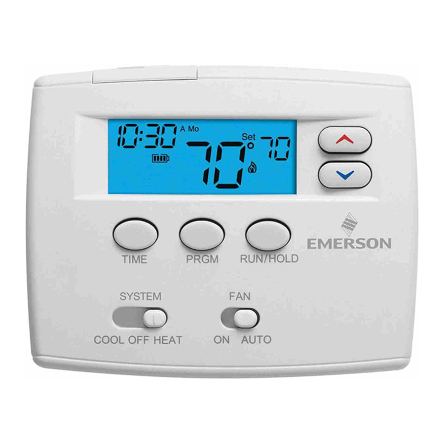
Blue 2" Heat Pump Thermostat
Installation and Operating Instructions
Model
1F82-0261
Yes
Yes
Yes
No
Yes
Yes
Yes
Yes
Yes
Yes
No
Index
www.white-rodgers.com
1
Heat Pump or Single Stage
Programming Choices
5/1/1 Day Programmable
1F82-0261 Thermostat
PART NO. 37-7022B
Replaces 37-7022A
Page
2
3
4
5
6
7
9
0925
Advertisement
Table of Contents

Related Manuals for White Rodgers 1F82-0261


Summary of Contents for White Rodgers 1F82-0261
-
Page 1: Table Of Contents
5/1/1 Day Programmable CONTROL COULD CAUSE PERSONAL INJURY AND/OR PROPERTY DAMAGE. APPLICATIONS YOUR THERMOSTAT REPLACES 1F82-0261 Thermostat Description Heat Pump (No Aux. or Emergency Heat) Heat Pump (with 1 Aux. or Emergency Heat Stage) Standard Heat & Cooling Systems Two Stage Heat & Two Stage Cool... -
Page 2: Installation
INSTALLATION Battery REMOVE OLD THERMOSTAT Door 1. Shut off electricity at the main fuse box until installation is complete. Ensure that electrical power is disconnected. 2. Remove the front cover of the old thermostat. With wires still attached, remove wall plate from the wall. If the old thermostat has a wall mounting plate, remove the Mounting Hole... -
Page 3: Wiring Diagrams
INSTALLATION install fresh “AA” alkaline batteries immediately. For best EMR – Heat Pump Example: results, use new premium brand alkaline batteries such as If the thermostat is programmed to an overnight heating Duracell® or Energizer®. We recommend replacing batteries temperature of 66°F, and the next program period, beginning at every 2 years. -
Page 4: Thermostat Quick Reference
WIRING DIAGRAMS NOTE Polarity must be observed. If the HOT side of the second transformer is jumpered to the COMMON side of the first transformer a short will be made. Damage to equipment will occur when power is restored. THERMOSTAT SYSTEM Limit or Safety... -
Page 5: Installer Confi Guration Menu
INSTALLER/CONFIGURATION MENU The confi guration menu allows you to set certain thermostat operating characteristics to your system or personal requirements. To enter the menu: Set your thermostat to OFF and press the buttons simultaneously. The display will show the fi rst item in the confi guration menu. Press RUN/HOLD to change to the next menu item or press TIME to go backwards to the previous item in the menu. -
Page 6: Operation
INSTALLER/CONFIGURATION MENU 4 & 5) Select Cycle Rate Selection - The factory default 8) Select Temperature Display Adjustment 4 LO to 4 HI - setting is (FA, CR) for all modes (Heat Pump, Heat Pump Allows you to adjust the room temperature display up to 4° Aux, Heat and Cool, Single Stage Heat and Single Stage higher or lower. -
Page 7: Programming
PROGRAMMING If you want to change the preprogrammed times and CAUTION temperatures, follow these steps. Do not allow the compressor to run unless the Determine the time periods and temperatures for your program. compressor oil heaters have been operational for 6 You must program four periods for each day. -
Page 8: Enter Heating Program
PROGRAMMING Enter Heating Program Enter Cooling Program 1. Move the SYSTEM switch to HEAT. CAUTION 2. Press PRGM once. “Mo Tu We Th Fr” (indicating weekday program) will appear in the display. Also displayed are the If the outside temperature is below 50 F, disconnect currently programmed start time for the 1st heating period power to the cooling system before programming. -
Page 9: Troubleshooting
TROUBLESHOOTING Reset Operation the thermostat has power, has been reset and still does not If a voltage spike or static discharge blanks out the display or function correctly contact your heating/cooling service person causes erratic thermostat operation, reset the thermostat by or place of purchase. - Page 10 TROUBLESHOOTING STAGING Typical operation: In moderate weather with a low temperature setting (low Second Stage - Auxiliary Heat demand) the thermostat may use only the heat pump Most heat pump systems have an Auxiliary or Second Stage to maintain temperature. electric heater or gas furnace.
- Page 11 NOTES...
- Page 12 Homeowner Help Line: 1-800-284-2925 White-Rodgers is a division of Emerson Electric Co. The Emerson logo is a trademark and service mark www.white-rodgers.com of Emerson Electric Co.
Need help?
Do you have a question about the 1F82-0261 and is the answer not in the manual?
Questions and answers