Table of Contents
Advertisement
Save these instructions for future use!
FAILURE TO READ AND FOLLOW ALL INSTRUCTIONS
CAREFULLY BEFORE INSTALLING OR OPERATING THIS
CONTROL COULD CAUSE PERSONAL INJURY AND/OR
PROPERTY DAMAGE.
APPLICATIONS
THERMOSTAT APPLICATION GUIDE
Thermostat
Configuration
Options
Heat Pump
Single Stage Compressor
Single Stage
Heat Pump Systems - 1
Compressor
Stage Aux/Emergency Heat
SPECIFICATIONS
Electrical Rating:
Battery Power or Hardwire ............................. 20 VAC, 50/60 Hz
Terminal Load ........................................................ 1.0 A per terminal, 1.5A maximum all terminals combined
Setpoint Range ...................................................... 45° to 90°F (7° to 32°C)
Differential (Heat Pump) ........................................ Heat 1.2°F; Cool 1.2°F (adjustable)
Operating Ambient ................................................. 32° to +105°F (0° to +41°C)
Operating Humidity ................................................ 90% non-condensing max.
Shipping Temperature Range ................................ -40° to +150°F (-40° to +65°C)
Dimensions Thermostat ......................................... 3-3/4"H x 4-3/4"W x 1-1/2"D
PRECAUTIONS
WARNING
!
Do not use on circuits exceeding specified voltage.
Higher voltage will damage control and could cause
shock or fire hazard.
Thermostat installation and all components of the
system shall conform to Class II (current limited)
circuits per the NEC code. Failure to do so could cause
a fire hazard.
CAUTION
!
To prevent electrical shock and/or equipment damage,
disconnect electric power to system at main fuse or
circuit breaker box until installation is complete.
Thermostat
Maximum
Applications
Stages
Heat/Cool
2/1
www.white-rodgers.com
www.emersonclimate.com
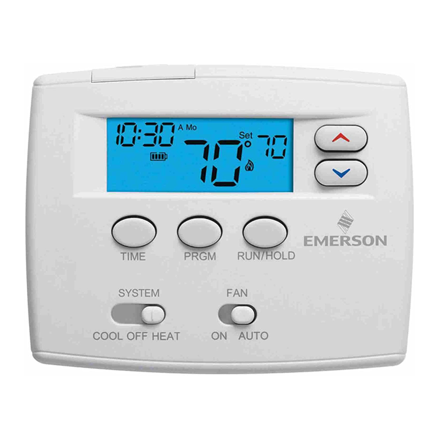
Blue 2" Heat Pump Thermostat
Heat Pump Installation and Operating Instructions
Model
1F82-0261
1F82-0261 Thermostat
Index
1
Programming Choices
5/1/1 Day Programmable
Page
2
3
4
5
6
7
9
PART NO. 37-7022C
Replaces 37-7022B
1023
Advertisement
Table of Contents

Summary of Contents for White Rodgers 1F82-0261
-
Page 1: Table Of Contents
To prevent electrical shock and/or equipment damage, disconnect electric power to system at main fuse or circuit breaker box until installation is complete. Blue 2” Heat Pump Thermostat Heat Pump Installation and Operating Instructions Model 1F82-0261 1F82-0261 Thermostat Maximum Stages Heat/Cool Index Installation Wiring Diagram... -
Page 2: Remove Old Thermostat
INSTALLATION REMOVE OLD THERMOSTAT 1. Shut off electricity at the main fuse box until installation is complete. Ensure that electrical power is disconnected. 2. Remove the front cover of the old thermostat. With wires still attached, remove wall plate from the wall. If the old thermostat has a wall mounting plate, remove the thermostat and the wall mounting plate as an assembly. -
Page 3: Wiring Diagram
INSTALLATION batteries should be replaced before leaving. When less than two months of battery life remain, the setpoint temperature will offset by 10 degrees (10 degrees cooler in Heat mode / 10 degrees warmer in Cool mode). If offset occurs, the normal setpoint can be manually reset with will occur within two days if batteries are not replaced. -
Page 4: Buttons And Switches
THERMOSTAT QUICK REFERENCE Before you begin programming your thermostat, you should be familiar with its features and with the display and the location and operation of the thermostat buttons and switches (see fig. 3). Your thermostat consists of two parts: the thermostat cover and the base. -
Page 5: Installer Configuration Menu
INSTALLER/CONFIGURATION MENU The configuration menu allows you to set certain thermostat operating characteristics to your system or personal requirements. To enter the menu: Set your thermostat to OFF and press the first item in the configuration menu. Press RUN/HOLD to change to the next menu item or press TIME to go backwards to the previous item in the menu. -
Page 6: Check Thermostat Operation
INSTALLER/CONFIGURATION MENU feature. Your compressor manufacturer can tell you if the lockout feature is already present in their system. When the thermostat compressor time delay occurs, it will flash the setpoint for up to five minutes. 6) Select Backlight Display - The display backlight improves display contrast in low lighting conditions. -
Page 7: Programming Your Thermostat
PROGRAMMING CAUTION Do not allow the compressor to run unless the compressor oil heaters have been operational for 6 hours and the system has not been operational for at least 5 minutes. MANUAL OPERATION • HOLD TEMPERATURE — With the SYSTEM switch set to HEAT or COOL, momentarily press RUN/HOLD button. -
Page 8: Check Your Programming
PROGRAMMING Enter Heating Program 1. Move the SYSTEM switch to HEAT. 2. Press PRGM once. “Mo Tu We Th Fr” (indicating weekday program) will appear in the display. Also displayed are the currently programmed start time for the 1st heating period and the currently programmed temperature (flashing). -
Page 9: Troubleshooting
TROUBLESHOOTING Reset Operation If a voltage spike or static discharge blanks out the display or causes erratic thermostat operation, reset the thermostat by pressing the and PRGM buttons simultaneously. If Symptom Possible Cause No Heat/No Cool/No Fan 1. Blown fuse or tripped circuit breaker. (common problems) 2. - Page 10 TROUBLESHOOTING STAGING Second Stage - Auxiliary Heat Most heat pump systems have an Auxiliary or Second Stage electric heater or gas furnace. Heat produced by a heat pump is economical but may not always have the capacity to maintain a comfortable room temperature setting. Auxiliary/Second Stage heat is usually less economical but the added heat capacity assures the system can provide enough heat to satisfy the thermostat setting.
- Page 11 NOTES...
- Page 12 Homeowner Help Line: 1-800-284-2925 White-Rodgers is a division of Emerson Electric Co. The Emerson logo is a www.white-rodgers.com trademark and service mark of Emerson Electric Co. www.emersonclimate.com...


Need help?
Do you have a question about the 1F82-0261 and is the answer not in the manual?
Questions and answers