Advertisement
Save these instructions for future use!
FAILURE TO READ AND FOLLOW ALL INSTRUCTIONS
CAREFULLY BEFORE INSTALLING OR OPERATING THIS
CONTROL COULD CAUSE PERSONAL INJURY AND/OR
PROPERTY DAMAGE.
APPLICATIONS
THERMOSTAT APPLICATION GUIDE
Description
Gas or Oil Heat
Electric Furnace
Heat Pump (No Aux. or Emergency Heat)
Heat Pump (with Aux. or Emergency Heat)
Systems with up to 3 Stages Heat, 2 Stages Cool
Heat Only Systems
Millivolt Heat Only Systems - Floor or Wall Furnaces
Cool Only Systems
Hydronic (Hot Water) Zone Heat - 2 Wires
Hydronic (Hot Water) Zone Heat - 3 Wires
SPECIFICATIONS
Electrical Rating:
Battery Power . . . . . . . . . . . . . . . . . . . . . . . . . mV to 30 VAC, NEC Class II, 50/60 Hz or DC
Input-Hardwire . . . . . . . . . . . . . . . . . . . . . . . . 20 to 30 VAC
Terminal Load . . . . . . . . . . . . . . . . . . . . . . . . . . . . 1.0 A per terminal, 1.5A maximum all terminals combined
Setpoint Range . . . . . . . . . . . . . . . . . . . . . . . . . . . 45° to 90°F (7° to 32°C)
Differential (Single Stage) . . . . . . . . . . . . . . . . . . . Heat 0.6°F; Cool 1.2°F (adjustable)
Differential (Heat Pump) . . . . . . . . . . . . . . . . . . . . Heat 1.2°F; Cool 1.2°F (adjustable)
Operating Ambient . . . . . . . . . . . . . . . . . . . . . . . . . 32° to +105°F (0° to +41°C)
Operating Humidity . . . . . . . . . . . . . . . . . . . . . . . . 90% non-condensing max.
Shipping Temperature Range . . . . . . . . . . . . . . . . -4° to +150°F (-20° to +65°C)
Dimensions Thermostat . . . . . . . . . . . . . . . . . . . . . 3.4"H x 4.4"W x 1.3"D
CAUTION
!
To prevent electrical shock and/or equipment dam-
age, disconnect electric power to system at main fuse
or circuit breaker box until installation is complete.
Index
80 Series Thermostat with
80 Series Thermostat with
80 Series Thermostat with
80 Series Thermostat with
80 Series Thermostat with
Automatic Heat/Cool Changeover Option
Automatic Heat/Cool Changeover Option
Automatic Heat/Cool Changeover Option
Automatic Heat/Cool Changeover Option
Automatic Heat/Cool Changeover Option
Installation and Operating Instructions for Model:
Model
1F80-0471
1F86-0471
Yes
Yes
Yes
No
No
Yes
Yes
Yes
Yes
Yes
ATTENTION: MERCURY NOTICE
This product does not contain mercury. However, this
product may replace a product that contains mercury.
Mercury and products containing mercury must not be
discarded in household trash. Do not touch any spilled
mercury. Wearing non-absorbent gloves, clean up any
Page
spilled mercury and place in a sealed container. For proper
2
disposal of a product containing mercury or a sealed
2
container of spilled mercury, place it in a suitable shipping
3
container and send it to:
4
6
6
8
www.white-rodgers.com
Single Stage or Heat Pump
Programming Choices
5/2 Day 5/1/1 Day Non-Programmable
Non-Programmable
1F86-0471 Thermostat
White-Rodgers
2895 Harrison Street
Batesville, AR 72501
PART NO. 37-6749A
0604
Advertisement
Table of Contents

Related Manuals for White Rodgers 1F86-0471


Summary of Contents for White Rodgers 1F86-0471
-
Page 1: Table Of Contents
5/2 Day 5/1/1 Day Non-Programmable CONTROL COULD CAUSE PERSONAL INJURY AND/OR 1F86-0471 Non-Programmable PROPERTY DAMAGE. APPLICATIONS 1F86-0471 Thermostat THERMOSTAT APPLICATION GUIDE Description Gas or Oil Heat Electric Furnace Heat Pump (No Aux. or Emergency Heat) Heat Pump (with Aux. or Emergency Heat) -
Page 2: Installation
INSTALLATION Once fully down, snap the door back into position. To WARNING replace the batteries, set system to OFF, following the instructions above. Thermostat installation and all components of the Figure 1 – Battery door shown open control system shall conform to Class II circuits per the NEC code. -
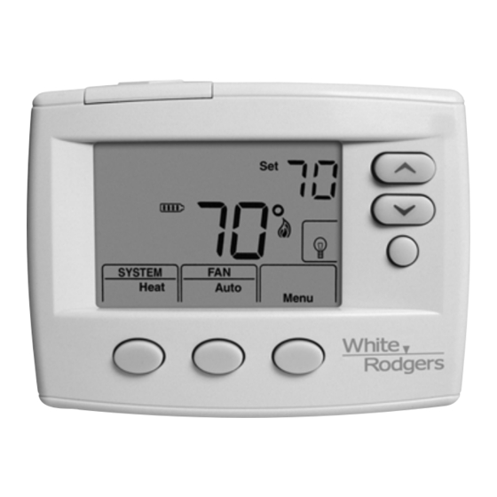
Page 3: Thermostat Quick Reference
THERMOSTAT QUICK REFERENCE Figure 4 – Home Screen Display Home Screen Description Room Time Temperature Setting Day of Week Temperature Displays the power level of the 2 "AA" batteries: indicates good power level. indicates batteries at about Temperature Up/Down half power. “Change ”... -
Page 4: Installer Configuration Menu
INSTALLER/CONFIGURATION MENU Press the Menu button for at least 5 seconds. The display will show item #1 in the table below. Press Menu to advance to the next menu item. Press to change a menu item. INSTALLER/CONFIGURATION MENU MENU PRESS DISPLAYED Press REF. - Page 5 INSTALLER/CONFIGURATION MENU 4) Energy Management Recovery: (this step is skipped if 9) System Mode Configuration – This thermostat is configured to be non-programmable). configured for Heat and Cool with Auto changeover Energy Management Recovery (E) On enables the (SYSTEM switch with Cool Off Heat Auto) default. It can thermostat to start heating or cooling early to make the also be configured for Heat and Cool (Cool Off Heat), building temperature reach the program setpoint at the...
-
Page 6: Operating Your Thermostat
OPERATING YOUR THERMOSTAT IMPORTANT! Choose the Fan Setting (Auto or On) Manual Operation (Bypassing the Program) Programmable Thermostats Set the FAN Switch to Auto or On. Fan Auto is the most commonly selected setting and runs Press and the HOLD button and adjust the temperature wherever you like. - Page 7 PROGRAMMING (For Programmable Model Only) Energy Saving Factory Pre-Program The 1F80-0471 thermostats are programmed with the energy saving settings shown in the table below for all days of the week. If this program suits your needs, simply set the thermostat clock and press the RUN button. The table below shows the factory set heating and cooling schedule for all days of the week.
-
Page 8: Troubleshooting
TROUBLESHOOTING Reset Operation Note: When thermostat is reset, installer configuration menu settings and programming will reset to factory settings. If a voltage spike or static discharge blanks out the display or causes erratic thermostat operation, you can reset the thermostat by removing the wires from terminals R and C (do not short them together) and removing batteries for 2 minutes.
Need help?
Do you have a question about the 1F86-0471 and is the answer not in the manual?
Questions and answers
1) How can I change from Fahrenheit to Celcius 2) How can I deactivate the back light, mine is always on blue screen 3) The thermostat fan is on auto and cool but the temperature never gets to the setting temperature