Table of Contents
Advertisement
I N S T A L L A T I O N
Quickstart Exterior - 9325e
1. Connect the black pair of wires to a 12VDC supply.
Observe proper polarity see Fig.1
2. The white pair of wires provide connection to a field
selectable N/O or N/C SPST relay (see Fig. 1).
3. The gray pair of wires. May be connected to a normally
open switch (for example: a N/O pushbutton switch) to
operate the electric release from the secure side
of the door.
Fig. 1
Black/White
9325e wiring
Wire
connections
Gray
Wires
Fig. 2
9325i wiring
connections
Quickstart Interior - 9325i
1. Connect a 12VDC supply to the power terminals of the
keypad. Observe proper polarity as illustrated in Fig.2
2. Connect the device to be controlled by the keypad to the
relay terminals of the keypad. These terminals can
operate as a N/O or N/C relay or a 12VDC powered
output. See connection diagram in Fig. 2. The Relay
terminals operate as a SPST relay by default, if a 12VDC
powered output is desired see Fig. 9 for details
3. Connect a N/O pushbutton to the Exit button terminals if
desired. A button wired to these terminals may be used
to operate an electric release from a remote location.
IS9325
USA: 2697 INTERNATIONAL PARKWAY, PKWY 5, VIRGINIA BEACH, VA 23452 • CANADA: 210 SHEARSON CRESCENT, CAMBRIDGE, ON N1T 1J6
PHONE • 1.800.265.6630 • 519.621.7651 • FAX: 1.800.482.9795 • 519.621.7939 • E-MAIL: SALES@RUTHERFORDCONTROLS.COM
+
-
Black Wire
White Wires
1
2
3
4
5
6
7
8
9
*
0
#
+
–
Exit
Button
Power
Relay
May be SPST relay
or 12VDC output.
J2
(See Fig. 9 for
J3
details.)
J4
©2010 RUTHERFORD CONTROLS INT'L CORP. WWW.RUTHERFORDCONTROLS.COM
First – the master code must be set (allows access to all
keypad settings).
The first time the keypad is turned on, the green and red
LEDs will flash alternately.
Choose a 6 digit number and make a note of it here. This will
be the new master code.
Press ✱ followed by the new master code then...
Press ✱ and re-enter the new master code then...
Press ✱ to confirm the code, and finish.
Now that the master code is defined, type 7890 on the
keypad. The door should open.
Note: The master code must not contain a user code (for
example: 123456 as a master code and 1234 as a user code
would cause the door to open before the master code had
been entered, a full system reset would be required).
Then set the user code (opens the door)
Choose an entry code (at least 4 digits, but not more than 8)
and make a note of it here. This will be the new user entry
code.
Enter the 6 digit master code (green and red start flashing
together).
+
–
Press and hold down 8 for 3 seconds then...
Enter the new user entry code and press ✱ then...
Re-enter the new user entry code and press ✱ then...
Press 1 to confirm the code.
Press # to exit programming mode.
Resetting
If you want to start again, simply turn off the power to the
keypad. Press and hold the 3 (or 2) while turning the power
back on. This will reset everything back to the factory
settings.
Multiple codes
For more than one user code, see page 3 programming that
allows the keypad to accept multiple user codes.
The factory default user code 7890 should be deleted once
the new multi-codes have been entered.
In multi-user mode, a [✱] is required after the user code to
unlock the door.(for example, 1234✱).
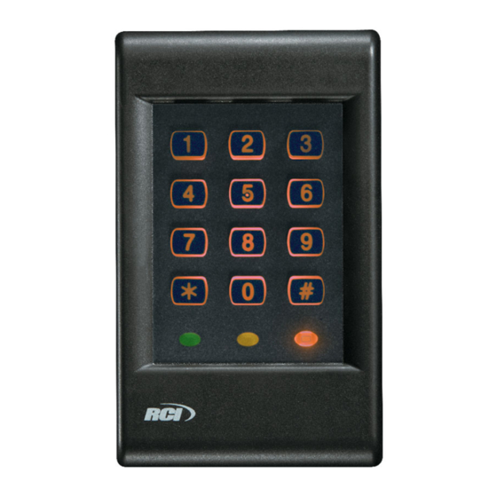
Access Keypad
Quickstart Programming
master code
user code
9325
R04/10SH
Advertisement
Table of Contents

Subscribe to Our Youtube Channel
Related Manuals for RCI 9325


Summary of Contents for RCI 9325
- Page 1 I N S T A L L A T I O N 9325 Access Keypad Quickstart Exterior - 9325e Quickstart Programming 1. Connect the black pair of wires to a 12VDC supply. First – the master code must be set (allows access to all Observe proper polarity see Fig.1...
- Page 2 9325 Keypad Installation Instructions (Continued) 9325i Interior Keypad 9325e Weatherproof or Exterior Keypad 9325e is a sealed unit and cannot be opened. Fig. 4 Items Supplied with 9325e. If any items are Fig. 3 Items Supplied with 9325i. If any items are missing or damaged, please contact your vendor.
- Page 3 9325 Keypad Installation Instructions (Continued) Programming Codes For basic operation, see the Quickstart guide on page 1. Programming additional features in the keypad are shown below. Enter the 6 digit master code Select an option by pressing a number and holding it down for 3 seconds...
- Page 4 9325 Keypad Installation Instructions (Continued) Programming Descriptions How to change the master code How to set up the keypad to work with a fail Find out the existing 6 digit master code. (If you do not unlocked release know this, see if it is written in the Quickstart section of this A fail unlock release is used where it is necessary for the manual.) The master code is used to change all the keypad...
-
Page 5: Specifications
9325 Keypad Installation Instructions (Continued) Specifications Troubleshooting Relay rating: 5A @ 30V I have connected the keypad correctly, but it does not open Power requirements: 12VDC when I enter my code. Check that there is power to the keypad by pressing the keys... - Page 6 9325 Keypad Installation Instructions (Continued) Note: To use the 9325 Keypad with an electric strike, the output relay must be programmed as Fail Locked. See programming instructions on p. 3. For use with an electromagnetic lock, see Figs. 9, 10 and 11.
- Page 7 9325 Keypad Installation Instructions (Continued) Note: To use the 9325 Keypad with an electromagnetic lock the output relay must be programmed as Fail Unlocked. See programming instructions on p. 3. For use with an electric strike, see Figs. 7, and 8 .
- Page 8 R E F E R E N C E C H A R T WIRE GAUGE SELECTION Load Current @ 24V Total One-Way Length of Wire Run (ft.) 1/4A 1/2A 3/4A 1-1/4A 1-1/2A — — — — — — — —...
Need help?
Do you have a question about the 9325 and is the answer not in the manual?
Questions and answers