Advertisement
I N S T A L L A T I O N
Features:
• Flush Mount, Single Gang
• Illuminated Backlit Keys
• Keypad Programmable
• Keypress Feedback via Built-In Sounder
• Bi-Color Red/Green LED Indicates Relay Status
• Yellow LED Indicates Program Mode
• 120 Users
• Single Use Codes
• Lockout Users
• Passage/Toggle Codes
• 10 to 30 Volt DC Operation
• 12 to 24 Volt AC Operation
• 2 Amp Main Relay
• Remote Trigger Input (REX)
• 2 Year Warranty
Specifications:
Parameter
Voltage
Current
Environment
Temperature Tolerance
Dimensions
Main Relay (Form C)
REX Input
Door Position Input
LEDs
Parameter
Master Code
Lock Output
Audio Alerts
REX
REX Operation
Error Lockout / Threshold
Error Lockout Duration
Lock Output Time
Visual / Audio Keypress Feedback
Auto-Entry
User Lockout
usA: 2517 sQuAdRon couRt, suIte 104, VIRGInIA BeAch, VA 23453 • cAnAdA: 210 sheARson cRescent, cAmBRIdGe, on n1t 1j6
IS9212iLW
Phone • 1.800.265.6630 • 519.621.7651 • fAX: 1.800.482.9795 • 519.621.7939 • e-mAIl: sAles@RutheRfoRdcontRols.com
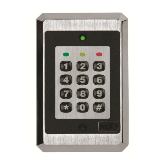
Interior/Exterior Use Stand-Alone Keypad
Product Description:
The 212iLW keypad features a single-relay output to control any
device requiring an on/off switch. The output is timed or latched and
operated by a user's PIN code. Additionally, the 212iLW keypad
provides basic keyless entry by controlling a door locking device
where security is not an issue.
The 212iLW style keypads are designed for both indoor and outdoor flush
mount applications. The electronics are conformal coated in the
manufacturing process in order to provide this level of application
flexibility. In addition, each keypad uses hardened keys to assure long-term,
high-quality performance.
Each keypad contains illuminated clear keys that make operation in low
light situations easy and accurate. iLW style keypads mount to any standard
single-gang electrical box or directly to any wall.
Range/Description
10–30 VDC, 12-24VAC (Auto-Adjusting)
93mA @ 10VDC; 158mA @ 30VDC, 148mA @ 12VAC; 198mA @ 24VAC
For Indoor and Outdoor Use
-20° F to 130° F (-28° C to 54° C)
5 1/8" H x 3 3/8" W x 5/8" D
Contact Rating: 2A @ 30VAC/DC
Normally Open Dry Contact
Normally Closed Dry Contact
Bi-Color Red/Green; Yellow
Default Keypad Settings
Default Setting
1234
Relay 1 ( Main relay )
Not assigned
Triggers Lock Output
Always Triggers (regardless of Door Loop)
Enabled / 3 Attempts
10 seconds
5 seconds
Enabled
Disabled
Enabled
©2013 RutheRfoRd contRols • www.RutheRfoRdcontRols.com
9212iLW
PCN13023
R11/13CA
Advertisement
Table of Contents

Related Manuals for RCI 9212ilw


Summary of Contents for RCI 9212ilw
- Page 1 9212iLW I N S T A L L A T I O N Interior/Exterior Use Stand-Alone Keypad Features: Product Description: • Flush Mount, Single Gang The 212iLW keypad features a single-relay output to control any • Illuminated Backlit Keys device requiring an on/off switch. The output is timed or latched and • Keypad Programmable operated by a user’s PIN code. Additionally, the 212iLW keypad • Keypress Feedback via Built-In Sounder provides basic keyless entry by controlling a door locking device • Bi-Color Red/Green LED Indicates Relay Status where security is not an issue. • Yellow LED Indicates Program Mode • 120 Users The 212iLW style keypads are designed for both indoor and outdoor flush • Single Use Codes mount applications. The electronics are conformal coated in the • Lockout Users manufacturing process in order to provide this level of application • Passage/Toggle Codes flexibility. In addition, each keypad uses hardened keys to assure long-term,...
-
Page 2: Signal Name
9212iLW Keypad Installation Instructions (Continued) MoUntIng The keypad is designed to be flush mounted using a standard single gang electrical box. In addition, it can be flush mounted directly to the wall surface by cutting a hole in the wall. To properly size the mounting and wire access hole, use the installation template on the last page in this manual. Mounting height can vary depending on requirements. An appropriate range is typically between 48 and 52 inches on center off the floor. For outdoor installations, use a weatherproof back box and seal the wire entry locations with silicone and provide a drain hole. In addition, use the anti-oxidant grease pack for Figure 1 Keypad the wire harness connectors. Mounting Height WIrIng Wire Harness Configuration Wire Color Signal name Red V+ (Keypad Power) Black V- (Keypad Power) White/Black Not Used White/Yellow Not Used Brown Remote Trigger (REX) White/Orange Loop Common (REX and Door Loop) White... -
Page 3: Testing The Keypad
KEyPAD After installing the keypad, RCI recommends that you perform the keypad self-test once a year, to ensure that the keypad works properly. 1. To perform the self-test, with the unit powered up, press the following keys on the keypad: 7890#123456* • If all 12 keypresses are accepted, the keypad enters self-test mode. -
Page 4: Programming Users
9212iLW Keypad Installation Instructions (Continued) ProgrAMMIng USErS to enter program mode press 99 # master code *. Command/Action Keys to Enter/Details User #1 is the master code; it can access all commands in program mode. The default code is 1234. The master code Master Code can be programmed with 60 as a standard user only. User #2, when programmed, is the supervisor code. The supervisor can access program mode, but is limited to Supervisor Code adding and deleting users, as well as enabling or disabling users. The supervisor code can’t change, delete, or disable the master code or supervisor code itself. Add Standard User (short version) user location # code * code * Add User with Specific Unlock unlock time # user location # code * code * (This command is used to program a user with a specific unlock time. Time This user activates the virtual lock output.) Delete User user location # * * Command 60. 60 # user type # user location # code * code *... -
Page 5: Programming Keypad Options
9212iLW Keypad Installation Instructions (Continued) ProgrAMMIng KEyPAD oPtIonS to enter program mode press 99 # master code *. Command/Action Keys to Enter/Details Command 30. 30 # option # enable/disable # * * Enable/Disable Keypad Options Option Disable Enable 0 – Audio Keypress Feedback 0 = disabled 1 = EnABLED 1 = EnABLED 1 – Visual Keypress Feedback... -
Page 6: Troubleshooting
The master code does not work. command. Power is not reaching the keypad. Using a voltmeter, confirm that there is voltage at the keypad on the red and black wires. If there is no voltage at the keypad, verify that there is voltage at the power supply. If there is no voltage at the power supply, call the manufacturer of the power No LEDs are lit on the keypad supply. If there is voltage at the power supply but not at the keypad, verify there is no break in the wires, then check continuity in the whole length of the wire run. To verify that the keypad is working, you can power the keypad with a 12-Volt Battery. If the keypad still does not work after troubleshooting, please call RCI’s techinal support department at 1-800-265-6630 or 519-621-7651. WIrE HArnESS LooPBACK ConnECtIonS If the Master Code is either not working or forgotten, power down the system, connect the wire harness as shown in Figure 7 below, and then power the system up again. The unit should now be in program mode. Next, change your Master Code using the programming command and power down the system and restore the wire harness to its original configuration and power the system back up. Figure 7 Program Mode Loopback...
Need help?
Do you have a question about the 9212ilw and is the answer not in the manual?
Questions and answers