Table of Contents
Advertisement
RCI-2950 DX
RCI-2970 DX
CHAPTER 1
1.0
General . . . . . . . . . . . . . . . . . . . . . . . . . . . . . . . . . . . . . . . . . . . . . . . .
1.1
Transmitter . . . . . . . . . . . . . . . . . . . . . . . . . . . . . . . . . . . . . . . . . . . . .
1.2
Receiver . . . . . . . . . . . . . . . . . . . . . . . . . . . . . . . . . . . . . . . . . . . . . . .
CHAPTER 2
INTRODUCTION
2.0
Introduction . . . . . . . . . . . . . . . . . . . . . . . . . . . . . . . . . . . . . . . . . . . .
2.1
Features . . . . . . . . . . . . . . . . . . . . . . . . . . . . . . . . . . . . . . . . . . . . . . .
CHAPTER 3
3.0
Introduction . . . . . . . . . . . . . . . . . . . . . . . . . . . . . . . . . . . . . . . . . . . .
3.1
Control & Connections . . . . . . . . . . . . . . . . . . . . . . . . . . . . . . . . . . . .
3.2
Microphone . . . . . . . . . . . . . . . . . . . . . . . . . . . . . . . . . . . . . . . . . . . .
3.3
Operation . . . . . . . . . . . . . . . . . . . . . . . . . . . . . . . . . . . . . . . . . . . . . .
CHAPTER 4
PROGRAMMING
4.0
Introduction . . . . . . . . . . . . . . . . . . . . . . . . . . . . . . . . . . . . . . . . . . . .
4.1
Frequency Selection . . . . . . . . . . . . . . . . . . . . . . . . . . . . . . . . . . . . . .
4.2
Frequency Scanning . . . . . . . . . . . . . . . . . . . . . . . . . . . . . . . . . . . . . .
4.3
Offset Frequency Operation . . . . . . . . . . . . . . . . . . . . . . . . . . . . . . . .
CHAPTER 5
5.0
Introduction . . . . . . . . . . . . . . . . . . . . . . . . . . . . . . . . . . . . . . . . . . . .
5.1
PLL Circuit . . . . . . . . . . . . . . . . . . . . . . . . . . . . . . . . . . . . . . . . . . . . .
5.2
Receiver Circuit . . . . . . . . . . . . . . . . . . . . . . . . . . . . . . . . . . . . . . . . .
5.3
Transmitter Modulation Circuit . . . . . . . . . . . . . . . . . . . . . . . . . . . . .
5.4
Transmitter Amplifier Circuit . . . . . . . . . . . . . . . . . . . . . . . . . . . . . . .
CHAPTER 6
6.0
Required Test Equipment . . . . . . . . . . . . . . . . . . . . . . . . . . . . . . . . . .
6.1
Alignment Procedures . . . . . . . . . . . . . . . . . . . . . . . . . . . . . . . . . . . .
CHAPTER 7
7.0
Precautions . . . . . . . . . . . . . . . . . . . . . . . . . . . . . . . . . . . . . . . . . . . . .
7.1
Periodic Inspection . . . . . . . . . . . . . . . . . . . . . . . . . . . . . . . . . . . . . . .
7.2
Fuse Replacement . . . . . . . . . . . . . . . . . . . . . . . . . . . . . . . . . . . . . . . .
CHAPTER 8
DIAGRAMS AND PART LIST
8.0
PCB Layout & Part List . . . . . . . . . . . . . . . . . . . . . . . . . . . . . . . . . . .
TABLE OF
CONTENTS
PAGE
2
2
2
3
3
4
4
8
8
11
11
11
13
14
14
14
14
14
18
18
22
22
22
23
- 1 -
Advertisement
Table of Contents

Related Manuals for Ranger Communications RCI-2950 DX


Summary of Contents for Ranger Communications RCI-2950 DX
-
Page 1: Table Of Contents
RCI-2950 DX TABLE OF RCI-2970 DX CONTENTS PAGE CHAPTER 1 SPECIFICATIONS General .......... -
Page 2: Specifications
CHAPTER 1 RCI-2970 DX SPECIFICATIONS 1.0 GENERAL Model RCI-2950 DX / RCI-2970 DX Frequency Range 12 meter : 24.8900 ~ 24.9900 MHz 10 meter : 28.0000 ~ 29.6900 MHz Tuning Steps 100 Hz, 1 KHz, 10 KHz, 100 KHz, 1 MHz... -
Page 3: Introduction
INTRODUCTION 2.0 INTRODUCTION The Ranger RCI-2950 DX / RCI-2970 DX is a solid-state, fully synthesized Amateur 10 and 12 meter dual band mobile transceiver with full band coverage from 28.0000 MHz to 29.6999 MHz and 24.8900 MHz to 24.9900 MHz and all mode operation, including: AM, FM, USB, LSB, CW and PA modes. -
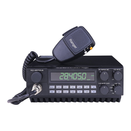
Page 4: Operation
RCI-2970 DX OPERATION Figure 3-1 Front Panel 3.0 INTRODUCTION This section explains the basic operating procedures for the RCI-2950 DX / RCI-2970 DX Amateur 10 and 12 meter dual band mobile transceiver. 3.1 CONTROL AND CONNECTIONS 3.1.1 FRONT PANEL Refer to the above Figure 3-1 for the location of the following controls. - Page 5 4. ON/OFF VOLUME CONTROL This knob controls the volume and the power to the radio. To turn the radio on, rotate knob clockwise. Turning the knob further will increase the volume of the receiver. 5. SQUELCH CONTROL This switch is used to eliminate background noise being heard through the receiver which can be disturbing when no transmissions are being received.
- Page 6 16. SWR BUTTON (SWR) This control is used to check SWR. 17. SCAN BUTTON (SCAN) This is used to scan frequencies in each band segment. The OPERATION segment of this manual provides detailed information on using the SCAN control. 18. MEMORY BUTTON (MEM) This button is used to program memory channels.
- Page 7 3.1.2 REAR PANEL Figure 3-2 represents the location of the following connections: Figure 3-2 Rear Panel 1. ANTENNA This jack accepts 50 ohms coaxial cable with a PL-259 type plug. 2. CW KEY This jack is for Morse code operation, To operate, connect a CW key to this jack and place the MODE switch in the CW position.
-
Page 8: Microphone
3.3.2 MODE SELECTION To select an operating mode on your RCI-2950 DX / RCI-2970 DX, simply rotate the MODE selector and place it in the desired operating mode position. - Page 9 3.3.6 MEMORY FUNCTION The RCI-2950 DX / RCI-2970 DX can store up to 10 most frequently used frequencies (from 0 to 9). To program a frequency into memory, follow the procedure described below: (1) Press the MAN button.
- Page 10 If several bars appear, your antenna needs adjusting. 3.3.9 CTCSS - OPTIONAL The RCI-2950 DX / RCI-2970 DX can operate with CTCSS frequencies for accessing repeaters, with an optional CTCSS (Continuous Tone Coded Squelch System) encoding device installed. 3.3.10 PROCEDURE TO RECEIVE (1) Be sure that power source, microphone and antenna are connected to the proper connectors before going to the next step.
-
Page 11: Introduction
10 and 12 meter dual band mobile transceiver. 4.1 FREQUENCY SELECTION Frequency selection in the RCI-2950 DX / RCI-2970 DX can be accomplished using anyone of the three following methods: (1) The first method of frequency selection is through the use of the SHF (Shift) key and the (σ) Up and (τ) Down arrows. - Page 12 4.2.2 MEMORY SCANNING The RCI-2950 DX / RCI-2970 DX has 10 non-volatile (i.e. memory resident) memory locations which can be programmed with any available frequency within the operating band of the radio. The scan function of the unit can be programmed to scan these memory channels.
-
Page 13: Offset Frequency Operation
The RCI-2950 DX / RCI-2970 DX has an offset or split frequency feature that will permit the radio to be operated in a half-duplex mode. This will allow the user to talk on FM repeaters operating in the 10 and 12 Meter bands. -
Page 14: Circuit Description
RCI-2970 DX DESCRIPTION 5.0 INTRODUCTION This section explains the technical theory of operation for the RCI-2950 DX / RCI-2970 DX mobile transceiver. 5.1 PLL CIRCUIT The Phase Lock Loop (PLL) circuit is responsible for developing the receiver’s first local oscillator signal and the transmitter’s exciter signal. - Page 15 - 15 -...
- Page 16 - 16 -...
- Page 17 RCI-2950 DX / RCI-2970 DX CPU CIRCUIT DIAGRAM - 17 -...
-
Page 18: Alignment
RCI-2950 DX CHAPTER 6 RCI-2970 DX ALIGNMENT 6.0 REQUIRED TEST EQUIPMENT • † DC Power Supply (13.8VDC, 20A) Frequency Counter (100 MHz) ‚ ‡ RF Wattmeter (100W) RF Signal Generator (100 MHz) ƒ ˆ Multimeter Automatic Distortion Meter „ ‰... - Page 19 RCI-2970DX LEVELS ARE SHOWN IN []. ITEM U.U.T. SETTING ADJUST MEASUREMENT POINT TX Power Set radio to 28.000 MHz, AM TX mode. L18,L37,L35, Maximum Output. Modulation off. Set radio to 28.000 MHz, USB TX mode. AF signal 30mV, 1 KHz to microphone. Connect Oscilloscope to TP17.
- Page 20 ITEM SETTINGS ADJUST MEASUREMENT POINT AM Sensitivity Set radio to 28.000 MHz, AM RX mode. L5,6,7,8,9,10 Audio Output > 2V Set Clarifier Control to 12 o’clock. ,2,3 S/N > 10 dB Set RF Gain Fully Clockwise. Set SQ Fully Counter Clockwise. Set NB/ANL/OFF switch to OFF position.
- Page 21 Figure 6-2 Receiver test setup - 21 -...
-
Page 22: Maintenance
RCI-2950 DX CHAPTER 7 RCI-2970 DX MAINTENANCE 7.0 PRECAUTIONS The inherent quality of the solid-state components used in this transceiver will provide many years of continuous use. Taking the following precautions will prevent damage to the transceiver. (1) Never key the transmitter unless an antenna or suitable dummy load is connected to the antenna receptacle. - Page 23 Information on most electrical and mechanical parts is included in the parts list. The reference designators are in alphanumeric order. 8.1 ORDERING REPLACEMENT PARTS Parts orders should be referred to the parts department at: • Ranger Communications, Inc. 401 W. 35 NATIONAL CITY, CA 91950-7909 Tel: (619) 426-6440...
- Page 24 PART LIST: RCI-2950 DX / RCI-2970 DX CH SW P.C.B ITEM REFERENCE NUMBER RANGER PART DESCRIPTION NUMBER EPT295090A CH SW P.C.B PCB CONN/S 3PIN CC0501037L 0.01µF 50WV (COPPER SIDE) CH SW P.C.B EWRT32051S ROTARY SW CH SW P.C.B EX07N41216 PCB CONN/S 3PIN...
- Page 25 PART LIST: RCI-2950 DX SWR P.C.B ITEM REFERENCE NUMBER RANGER PART DESCRIPTION NUMBER EPT360041Z SWR P.C.B R402 RCP141014Z 100 OHM 1/4W R401 RCP141214Z 120 OHM 1/4W C401,C402 CC0501037L 0.01µF 50WV D401,D402 ED1N00060P DIODE 1N60P JP2,JP3 WX01070710 JUMPER WIRE REMARK: COPPER SIDE (BLUE)
- Page 26 PART LIST: RCI-2970 DX POWER P.C.B ITEM REFERENCE NUMBER RANGER PART DESCRIPTION NUMBER EPA010010A POWER P.C.B R904 RCU141094Z 1 OHM 1/4W R905,R906 RCU142204Z 22 OHM 1/4W R902 RCM141024A 1K OHM 1/2 W R911 RCP121034Z 10K OHM 1/2W L902 RCP101004Z 10 OHM 1W R903 RCP202204Z 22 OHM 2W...
- Page 27 ITEM REFERENCE NUMBER RANGER PART DESCRIPTION NUMBER C902,C903 CC0503915L 390PF 50WV C906,C926,C932,C934, CC0501037L 0.01µF 50WV C937 C905,C920,C921,C923x2 CC0501047L 0.1µF 50WV C924x2,C925,C935,C939 ,C941,T901-T902x2, C927,C928,C930,C931, C933,C940,C929 C901 CC0508204A 82PF 50WV C918 CD3006804Z 68PF 300WV C916 CD3001514Z 150PF 300WV C917 CD5001018Z 100PF 500WV C908,C910,C936 CD3001814Z 180PF 300WV...
- Page 28 PART LIST: RCI-2950 DX / RCI-2970 DX VR P.C.B (A) ITEM REFERENCE NUMBER RANGER PART DESCRIPTION NUMBER EPT295050Z VR P.C.B (A) C501,C505 CC0501027L 0.001µF 50WV RF/MIC RV10203451 VR 1KA-5KB VOL/SQ RV50303453 VR 50KB-50KA J501,J505 EX07N41226 PCB CONN/S 2PIN J502-J504 EX07N41216...
- Page 29 PART LIST: RCI-2950 DX / RCI-2970 DX VR P.C.B (B) ITEM REFERENCE NUMBER RANGER PART DESCRIPTION NUMBER EPT295060Z VR P.C.B (B) C601 CC0501027L 0.001µF 50WV RF/CAL RV10203456 VR 1KB-20KB J601,J602 EX07N41216 PCB CONN/S 3PIN REMARK: LEFT: COMPONENT SIDE RIGHT: COPPER SIDE (BLUE)
- Page 30 PART LIST: RCI-2950 DX / RCI-2970 DX MIC P.C.B ITEM REFERENCE NUMBER RANGER PART DESCRIPTION NUMBER EPT295070Z MIC P.C.B C701-C703 CCM501025T 0.001µF 50WV J702,J703 EX07N48152 PCB CONN/S 2PIN J701 EX07N48244 PCB CONN/S 3PIN MIC P.C.B EX06N41111 MIC JACK REMARK: LEFT: COMPONENET SIDE (BLUE)
- Page 31 PART LIST: RCI-2950 DX / RCI-2970 DX BAND P.C.B ITEM REFERENCE NUMBER RANGER PART DESCRIPTION NUMBER EPT295090Z BAND P.C.B BAND P.C.B EWRT32053S ROTARY SW J402 EX07N41216 PCB CONN/S 3PIN J401 EX07N41261 PCB CONN/S 7PIN J403 WX01070706 JUMPER WIRE REMARK: LEFT: COMPONENT SIDE...
- Page 32 PART LIST: RCI-2950 DX / RCI-2970 DX KEY SW P.C.B ITEM REFERENCE NUMBER RANGER PART DESCRIPTION NUMBER EPT295031Z KEY SW P.C.B R701-R708 RCP161524Z 1.5K OHM 1/16W KEY SW P.C.B x 14pc EWPS33042X TACT SW D701-D708 EX01N40064 LED (WHITE) KEY SW P.C.B x 2pc...
- Page 33 - 33 -...
- Page 34 PART LIST: RCI-2950 DX / RCI-2970 DX CPU P.C.B ITEM REFERENCE NUMBER RANGER PART DESCRIPTION NUMBER EPT295042Z CPU P.C.B C604 CE0102277Z 220µF 10WV R606 RCU128204Z 82 OHM 2W R604 RCU121214Z 120 OHM 2W DISPLAY EX03N40460 LCD DISPLAY X601 EX14N46510 CERAMIC RESONATOR...
- Page 35 RCI-2950 DX / RCI-2970 DX MAIN PCB. REMARK: SMD COMPONENT SIDE (BLUE) - 35 -...
- Page 36 RCI-2950 DX / RCI-2970 DX MAIN PCB REMARK: COMPONENT SIDE (BLUE) - 36 -...
- Page 37 RCI-2950 DX / RCI-2970 DX MAIN PCB REMARK: COPPER SIDE (WHITE) - 37 -...
- Page 38 RCY013934Z PART LIST 39KΩ 0.1W R7,34,62,63,99,132, RCY014734Z 47KΩ 0.1W RCI-2950 DX MAIN PCB 175,198,229,234,319 ,200 RCY018234Z 82KΩ 0.1W REFERENCE RANGER DESCRIPTION R12,44,48,49,51,53, RCY011044Z 100KΩ 0.1W NUMBER PART NO. 76,77,106,109,114, EPT695010Z MAIN P.C.B 169,176,195,197,232 R315,317,318,321, RCY010004Z ,238,284,285,295, 0Ω 0.1W 303,312,125,156 R277...
- Page 39 C5,16,23,26,41,56, CK1473AB7R C221,223 CC0503915G 390PF 50WV 0.047µF 50WV 74,75,77,78,81,157, C220 CC1001037L 0.01µF 100WV 162,170,199,258,262 C219 CD3005614Z 560PF 300WV ,272,273,274,277, C13,24,27,28,52,63, CE0251067Z 10µF 25WV 283,284,296,80 72,102,103,128,168, CK2474AB7R 0.47µF 25WV 200,308 C144 CK5475AA7R C90,188,198 CE0252267Z 4.7µF 16WV 22µF 25WV C47,49,165,174,110, CK1223AB6U C42,43,45,154,183, CE0254767Z 0.022µF 50WV 47µF 25WV...
- Page 40 J16-50ZJ504)- EX07N49044 WIRE CONN/H RCI-2950 DX MISC. PART 60Z(J601) J28-60Z(J602) EX07N49108 WIRE CONN/H J12-42Z(J601) EX07N49109 WIRE CONN/H REFERENCE RANGER DESCRIPTION J10-42Z(CN605)- EX07N49110 WIRE CONN/H NUMBER PART NO. 70Z(J702/703) ES200820MC SPEAKER J27-90Z(J401) EX07N49115 WIRE CONN/H C259,260 CC0201036S C/C 0.01UF C259,260 CC0501036S 0.01µF 50WV...
- Page 41 R7,34,62,63,99,132, RCY014734Z PART LIST 47KΩ 0.1W 175,198,229,234,319 RCI-2970 DX MAIN PCB ,200 R26,107,112,181 RCY016834Z 68KΩ 0.1W RCY018234Z 82KΩ 0.1W REFERENCE RANGER DESCRIPTION R12,44,48,49,51,53, RCY011044Z 100KΩ 0.1W NUMBER PART NO. 76,77,106,109,114, EPT695010Z MAIN P.C.B 169,176,195,197,232 R315,317,318,321, RCY010004Z ,238,284,285, 0Ω 0.1W 303,312,125,156 R179 RCY011004Z R21,47,59,84,147,...
- Page 42 C5,16,23,26,41,56, CK1473AB7R C221,223 CC0503915G 390PF 50WV 0.047µF 50WV 74,75,77,78,81,157, C220 CC1001037L 0.01µF 100WV 162,170,199,258,262 C219 CD3005614Z 560PF 300WV ,272,273,274,277, C13,24,27,28,52,63, CE0251067Z 10µF 25WV 283,284,296,80 72,102,103,128,168, CK2474AB7R 0.47µF 25WV 200,308 C144 CK5475AA7R C90,188,198 CE0252267Z 4.7µF 16WV 22µF 25WV C47,49,165,174,110, CK1223AB6U C42,43,45,154,183, CE0254767Z 0.022µF 50WV 47µF 25WV...
- Page 43 J16-50ZJ504)- EX07N49044 WIRE CONN/H RCI-2970 DX MISC. PART 60Z(J601) J28-60Z(J602) EX07N49108 WIRE CONN/H J12-42Z(J601) EX07N49109 WIRE CONN/H REFERENCE RANGER DESCRIPTION J10-42Z(CN605)- EX07N49110 WIRE CONN/H NUMBER PART NO. 70Z(J702/703) ES200820MC SPEAKER J27-90Z(J401) EX07N49115 WIRE CONN/H C259,260 CC0201036S C/C 0.01UF C259,260 CC0501036S 0.01µF 50WV EX02N40210 FUSE 16V 7A...
- Page 44 Figure 6-3 Main PCB Adjustment Location - 44 -...
Need help?
Do you have a question about the RCI-2950 DX and is the answer not in the manual?
Questions and answers
I need the schematic for EPT2950-20A TO MIC JACK PLEASE
The schematic for the Ranger Communications RCI-2950 DX EPT2950-20A to the mic jack is not provided in the context. The context includes part numbers, component types, and descriptions, but no schematic diagrams or detailed circuit paths are shown. Therefore, the schematic cannot be determined.
This answer is automatically generated