
Related Manuals for Ranger Communications RCI-69FFC6


Summary of Contents for Ranger Communications RCI-69FFC6
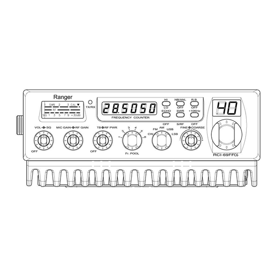
- Page 1 RCI-69FFC6 AM/FM/SSB/CW Amateur Transceiver with Built-in Frequency Counter User’s Manual...
-
Page 2: Table Of Contents
Table of Contents PAGE Chapter 1 Specifications ..…..........Chapter 2 Installation ..…..........Installing the Radio..............Ignition Noise Interference ............Antenna …................External Speaker ..............Public Address ............... Chapter 3 Operation ..…............Controls and Indicators ............Front Panel ................Rear Panel ................Operation …................ -
Page 3: Chapter 1 Specifications
Chapter 1 Specifications GENERAL Model RCI-69FFC6 Frequency Range : 1. 28.245 ~ 28.685 MHz 2. 28.695 ~ 29.135 MHz 3. 29.145 ~ 29.585 MHz 4. 28.315 ~ 28.755 MHz 5. 28.765 ~ 29.205 MHz 6. 29.215 ~ 29.655 MHz Modes... -
Page 4: Chapter 2 Installation
Chapter 2 Installation Installing the Radio Choose a convenient location for operation that does not interfere with driver or passenger. This radio is supplied with a universal mounting bracket. When mounting the bracket and radio to your car, make sure it is mechanically strong. -
Page 5: Ignition Noise Interference
Installation (Continued) 4. Mount the microphone bracket near the radio in an easily accessible spot using the two screws provided. Ignition Noise Interference With weak signals, you may experience interference of the signal by background noise. This radio has NB and ANL controls which will help reduce background noise from sources such as your ignition system. -
Page 6: Chapter 3 Operation
Chapter 3 Operation Controls and Indicators Front Panel 1. SQUELCH CONTROL: This control is used to control or eliminate receiver background noise in the absence of an incoming signal. For maximum receiver sensitivity, it is necessary that the control be adjusted only to the point where the receiver background noise is eliminated. - Page 7 Operation (Continued) 4. MIC GAIN CONTROL: Adjust the microphone gain in the transmit mode. This control is used to set the audio level of the microphone for maximum performance and clarity. 5. RF POWER CONTROL: This control enables adjustment of RF power output continuously up to the rated output power.
- Page 8 Operation (Continued) 15. HI/LOW TONE SWITCH: This switch changes tone quality in receive only. In LO position, bass is increased and in HI position, treble is increased. 16. S-RF/SWR SWITCH: In the S-RF position, the meter swings proportionally to the strength of the received signal. When transmitting, the meter indicates relative RF output power.
-
Page 9: Rear Panel
Operation (Continued) Rear Panel 1. ANTENNA: This jack accepts a 50 ohms coaxial cable with a PL-259 style plug. 2. POWER: This accepts 13.8 VDC power cable with built-in fuse. The power cord provided with the radio has a blue and red wire. The blue goes to negative and the red goes to positive. -
Page 10: Operation
Operation (Continued) Operation A. Microphone The receiver and transmitter are controlled by the push-to-talk switch on the microphone. Press the switch and the transmitter is activated, release switch to receive. When transmitting hold the microphone two inches from the mouth and speak clearly in a normal “voice”. The transceiver comes complete with low-impedance dynamic microphone. -
Page 11: Procedure To Receive
Operation (Continued) B. Procedure to Receive 1. Be sure that power source, microphone and antenna are connected to the proper connectors before going to the next step. 2. Turn unit on by turning VOL knob clockwise. 3. Set the VOL for a comfortable listening level. 4. -
Page 12: Memo
Memo - 11 -... - Page 13 Memo - 12 -...
- Page 14 Memo - 13 -...
-
Page 15: Limited Warranty
Ranger Communication, Inc. (Ranger) warrants to the original purchaser only this product against defects in material or workmanship, as noted below. The following Ranger Communications, Inc.'s products are covered by a one (1) year limited warranty: 1. Amateur Radio Products: RCI-2950DX, RCI-2970DX, RCI-2980WX, RCI-... - Page 16 867 Bowsprit Road Chula Vista, CA 91914 Email:sales@rangerusa.com http: //www.rangerusa.com PRINTED IN MALAYSIA P/N:A38251621D - 15 -...
Need help?
Do you have a question about the RCI-69FFC6 and is the answer not in the manual?
Questions and answers