
Related Manuals for Gefen GEF-HDFST-848-4ELR


Summary of Contents for Gefen GEF-HDFST-848-4ELR
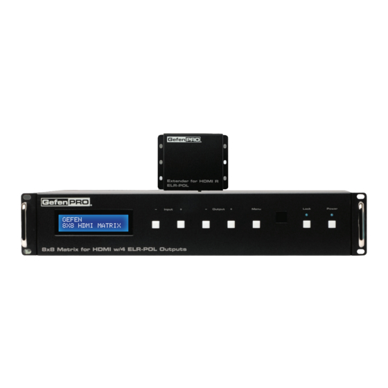
- Page 1 GEFEN 8x8 HDMI MAtRIX ® 1080P 8x8 Matrix for HDMI w/4 ELR-POL Outputs GEF-HDFST-848-4ELR User Manual www.gefenpro.com...
- Page 3 Notice Gefen, LLC reserves the right to make changes in the hardware, packaging, and any accompanying documentation without prior written notice. 8x8 Matrix for HDMI w/4 ELR-POL Outputs is a trademark of Gefen, LLC HDMI, the HDMI logo, and High-Definition Multimedia Interface are trademarks or registered trademarks of HDMI Licensing in the United States and other countries.
-
Page 4: Table Of Contents
CONTENTS Introduction Operation Notes Features Matrix Layout Front Back Matrix Descriptions Front Back ELR-POL Receiver Layout ELR-POL Receiver Descriptions IR Remote Control Layout and Description Installing the Battery Setting the IR Channel Connecting the 8x8 Matrix for HDMI w/4 ELR-POL Outputs Wiring Diagram Operating the 8x8 Matrix for HDMI w/4 ELR-POL Outputs Main Display... -
Page 5: Introduction
It features extension of four displays up to 330 feet (100 meters), using Gefen’s ELR (Extra Long Range) and POL (Power Over Link) technologies. ELR extension on four outputs allows installation of displays over a single CAT-5e cable. POL eliminates the need to externally power the four included ELR receivers. -
Page 6: Operation Notes
OPERATION NOTES READ THESE NOTES BEFORE INSTALLING OR OPERATING THE 8x8 MATRIx FOR HDMI W/4 ELR-POL OUTPUTS • EDID contains the A/V capabilities of a display device in regards to video resolutions and audio formats supported. This information is used by the source device to determine the format of the A/V signal on the outputs. -
Page 7: Features
ELR technology allows extension up to 330 feet (100 meters) • POL feature provides power to each ELR receiver • HDBaseT® technology • Gefen FST speeds up the HDCP authentication process • Fast and Slow FST Modes • Advanced EDID Management for rapid integration of sources and displays •... -
Page 8: Matrix Layout
MATRIx LAyOUT Front... -
Page 9: Back
MATRIx LAyOUT Back... -
Page 10: Matrix Descriptions
MATRIx DESCRIPTIONS Front LCD Display This is a two-line, sixteen-character display that shows status information and is also used to manage display / source routing. Navigation Buttons (Input / Output) Used for routing and adjusting settings of the 8x8 Matrix for HDMI w/4 ELR-POL Outputs. See the information beginning on page 15 for details on using these buttons. -
Page 11: Back
Grounding Screw Used to keep electrical current away from circuitry IR EXT Connect an IR extender (Gefen part no. EXT-RMT-EXTIRC) to this jack Service port for manufacturer use only. HDMI Locking Connector Used to lock the HDMI cable in place. -
Page 12: Elr-Pol Receiver Layout
ELR-POL RECEIVER LAyOUT Front Back... -
Page 13: Elr-Pol Receiver Descriptions
ELR-POL RECEIVER DESCRIPTIONS Top / Front / Back Power Indicator This LED indicator will glow bright blue when the matrix is powered and the ELR-POL Receiver unit is connected to the matrix using CAT-5e (or better) cable. HDMI Out Connect an HDTV display to the HDMI Out port using an HDMI cable. HDMI Locking Connector Used to lock the HDMI cable in place. -
Page 14: Ir Remote Control
IR REMOTE CONTROL Layout and Description (RMT-848IR) LED Button Press Indicator This LED will be activated momentarily each time a button is pressed. Display and Source Selection Buttons These buttons are used to select which source is routed to a display. The Source and Display buttons are mapped as follows: NOTE: An Activity Indicator that flashes quickly while holding down any one of the 16 buttons indicates a low battery. -
Page 15: Installing The Battery
IR REMOTE CONTROL Installing the Battery The Remote Control unit ships with two batteries (CR2032 lithium battery). One battery is required for operation and the other battery is a spare. Remove the battery cover on the back of the IR Remote Control unit. Insert the included battery into the open battery slot. -
Page 16: Wiring Diagram
RS-232 CABLE CAT-5 CABLE IR Extender CABLE Router IR Extender 8x8 Matrix for HDMI w/ELR POL HD Display HD Display RS-232 Controller HD Display Extender for HDMI R ELR POL HD Display HD Display HD Display HD Display HD Display GEF-HDFST-848-4ELR... -
Page 17: Main Display
This display shows the current routing status of the matrix and is also used to display additional system information. When the unit is powered on, the following screen is displayed: GEFEN 8x8 HDMI MATRIX After a few moments, the status screen is displayed. The status screen is shown below:... -
Page 18: Determining The Current Routing State
OPERATING THE 8x8 MATRIx FOR HDMI W/4 ELR-POL OUTPUTS Determining the Current Routing State In the example below, the first row (OUT) represents each HDMI output on the matrix. The bottom row (IN) represents each HDMI input on the matrix. Together, these two rows display the current routing state. -
Page 19: Routing Sources
OPERATING THE 8x8 MATRIx FOR HDMI W/4 ELR-POL OUTPUTS Routing Sources Selecting the Output To select the output, press the Out - or Out + button once. The routing state for Output A will be displayed: OUT:A IN:3 Press the Out - or Out + button to cycle through the routing state for each output. Consecutively pressing the Out + button will cycle through each output, from left to right. -
Page 20: Matrix
OPERATING THE 8x8 MATRIx FOR HDMI W/4 ELR-POL OUTPUTS Consecutively pressing the Out - button will cycle through each output, from right to left. OUT: Changing the Source Once the desired output has been selected, press the Input + or Input - button. Consecutively pressing the Input + button will increment the input value by a factor of 1 (within a range of 1 - 8). -
Page 21: Matrix
OPERATING THE 8x8 MATRIx FOR HDMI W/4 ELR-POL OUTPUTS Consecutively pressing the Input - button will decrease the input value by a factor of 1 (within a range of 1 - 8). For example, if Input 3 was originally routed to Output D, pressing the Input - button will route Input 2 to Output D. -
Page 22: Locking / Unlocking The Front Panel
OPERATING THE 8x8 MATRIx FOR HDMI W/4 ELR-POL OUTPUTS Locking / Unlocking the Front Panel To prevent an accidental routing change or power-down (by pressing the Power button), the front-panel buttons on the 8x8 Matrix for HDMI w/4 ELR-POL Outputs can be locked. Locking the matrix also disables many RS-232 / IP commands. -
Page 23: Fast Switching Technology
WITCHING ECHNOLOGY Fast Switching Technology Fast Switching Technology (FST) is a Gefen software implementation for HDMI products. FST was created to improve the lengthy HDMI authentication process, based on the HDMI and HDCP specifications. FST provides quicker audio/video source switching and greatly improves the overall audio/ video system behavior and performance when more than one HDTV display is used in the system setup. -
Page 24: Determining The Current Switching Mode
OPERATING THE 8x8 MATRIx FOR HDMI W/4 ELR-POL OUTPUTS Determining the Current Switching Mode Each HDMI input can be set to Fast Mode or Slow Mode. It is recommended that each HDMI input be set to Fast Mode for best performance. Consecutively press the Menu button on the front panel until the switching modes screen is displayed. -
Page 25: Matrix
OPERATING THE 8x8 MATRIx FOR HDMI W/4 ELR-POL OUTPUTS Press the Output - or Output + button again to cycle through the routing state for each output. Consecutively pressing the Output + button will cycle through each input, from left to right, starting with Input 1: NOTE: In Routing mode, the Output + and Output - buttons cycle through each output. -
Page 26: Changing The Switching Mode
OPERATING THE 8x8 MATRIx FOR HDMI W/4 ELR-POL OUTPUTS Changing the Switching Mode Once the desired input has been selected, press the Input + or Input - button to toggle between Fast or Slow switching mode. Switching mode changed from Fast to Slow on Input 3. -
Page 27: Matrix
OPERATING THE 8x8 MATRIx FOR HDMI W/4 ELR-POL OUTPUTS Setting the IR Channel on the 8x8 Matrix for HDMI In order for the 8x8 Matrix for HDMI w/4 ELR-POL Outputs to communicate with the included IR Remote Control, both the matrix and the IR Remote Control must be set to the same IR channel. -
Page 28: Matrix
OPERATING THE 8x8 MATRIx FOR HDMI W/4 ELR-POL OUTPUTS After setting the IR address, make sure that the DIP switches on the IR Remote Control are set according to the information in the LCD display. See page 11 for information on setting the IR channel for the IR Remote Control unit. IR ADDRESS : 1 1-ON , 2-OFF... -
Page 29: Routing Sources Using The Ir Remote Control
OPERATING THE 8x8 MATRIx FOR HDMI W/4 ELR-POL OUTPUTS Routing Sources using the IR Remote Control Buttons 1 - 8 on the IR remote control correspond to each HDMI input (Input 1 - 8) on the Matrix. Buttons A - D correspond to each HDMI output (Output A - D) and buttons E-H correspond to each ELR-POL output (Output E-H). -
Page 30: Matrix
OPERATING THE 8x8 MATRIx FOR HDMI W/4 ELR-POL OUTPUTS After the input and output have been selected on the IR Remote Control, the numbers on the far right-hand of the LCD display will disappear and the new routing state will be displayed in the LCD display: OUT:ABCDEFGH IN:33454681... -
Page 31: Edid Management
EDID MANAGEMENT External EDID Management The 8x8 Matrix for HDMI w/4 ELR-POL Outputs features EDID Management. Before the source can send video or audio signals, the source device reads the EDID (Extended Display Identification Data) from the output devices connected to the Splitter. The EDID contains information about what type of audio/video data that the source can send to each output device. -
Page 32: Rs-232 / Ip Control
RS-232 / IP CONTROL RS-232 Interface DE-9 DA-15 RS-232 Controller Matrix DB-25 Only TXD, RXD, and GND are used. DC-37 RS232 Settings Baud rate ........................19200 Data bits ..........................8 Parity bits ........................None Stop bits ..........................1 DD-50 Flow Control ........................None IMPORTANT: When sending RS-232 commands, a carriage return must be included at the end of the command. -
Page 33: Ip Configuration
RS-232 / IP CONTROL IP Configuration The 8x8 Matrix for HDMI w/4 ELR-POL Outputs supports IP-based control using Telnet, UDP, or the built-in Web-based GUI. To set up IP control, the network settings must be configured via RS-232. The default network settings for the matrix are as follows: IP Address: 192.168.1.72 Subnet:... -
Page 34: Rs-232 / Ip Commands
RS-232 / IP COMMANDS IP / Telnet Configuration Command Description #display_telnet_welcome Set Telnet welcome message on login #ipconfig Displays all TCP/IP settings #resetip Resets IP configuration to factory settings #set_http_port Sets the Web server listening port Prompts for password when using Telnet #set_telnet_pass #set_telnet_port Sets the Telnet listening port... -
Page 35: Display_Telnet_Welcome
RS-232 / IP COMMANDS #display_telnet_welcome Command The #display_telnet_welcome command sets (enables/disables) the Telnet welcome message on login. Syntax: #display_telnet_welcome param1 Parameters: param1 State [0 ... 1] State Meaning Do not display welcome message Display welcome message Example: #display_telnet_welcome 1 #Telnet Welcome Screen is Enable #display_telnet_welcome 0 #Telnet Welcome Screen is Disable... -
Page 36: Matrix
RS-232 / IP COMMANDS #ipconfig Command The #ipconfig command displays the current TCP/IP settings for the matrix. Syntax: #ipconfig Parameters: None Example: #ipconfig -------------- TCP/IP settings ------------- MAC add = 00:1C:91:01:50:07 IP add = 192.168.1.72 Net Mask = 255.255.255.0 Gateway = 192.168.2.1 Web Server Port = 80 Telnet Server Port = 23... - Page 37 RS-232 / IP COMMANDS #resetip Command The #resetip command resets all TCP/IP settings to factory defaults. Syntax: #resetip Parameters: None Notes: The matrix must be rebooted after executing this command. Example: #resetip IP Configuration Was Reset To Factory Defaults. After rebooting the matrix, the IP settings will be cleared. Running the #ipconfig command will display the updated information: #ipconfig IP: 0.0.0.0...
-
Page 38: Set_Http_Port
RS-232 / IP COMMANDS #set_http_port Command The #set_http_port command sets the Web server listening port. The default port setting is 80. Also see the #show_http_port on page 40. Syntax: #set_http_port param1 Parameters: Port [0 ... 65535] param1 Notes: The matrix must be rebooted after executing this command. Example: #set_http_port 70 HTTP Communication Port 80 Is Set. -
Page 39: Set_Telnet_Pass
RS-232 / IP COMMANDS #set_telnet_pass Command The #set_telnet_pass command sets the Telnet password. The maximum length of the password is 20 characters. The password is case-sensitive. The default Telnet password is Admin. Syntax: #set_telnet_pass param1 Parameters: param1 Password Notes: The matrix must be rebooted after executing this command. Example: #set_telnet_pass OK_Corral TELNET Interface Password Is Set. -
Page 40: Set_Telnet_Port
RS-232 / IP COMMANDS #set_telnet_port Command The #set_telnet_port command sets the Telnet listening port. The default port value is 23. Syntax: #set_telnet_port param1 Parameters: param1 Port [0 - 65535] Notes: The matrix must be rebooted after executing this command. Example: #set_telnet_port 20 Telnet Communication Port 23 Is Set. -
Page 41: Set_Webui_Ad_Pass
RS-232 / IP COMMANDS #set_webui_ad_pass Command The #set_webui_pass command sets the Adminstrator password for the Web interface. The maximum length of the password is 8 characters. The default password is Admin. Syntax: #set_webui_ad_pass param1 Parameters: Password param1 Notes: The matrix must be rebooted after executing this command. Example: #set_webui_ad_pass reindeer Web UI Administrator Password Is Set. - Page 42 RS-232 / IP COMMANDS #set_webui_op_pass Command The #set_webui_pass command sets the Operator password for the Web interface. The maximum length of the password is 8 characters. The default password is Admin. Syntax: #set_webui_op_pass param1 Parameters: Password param1 Notes: The matrix must be rebooted after executing this command. Example: #set_webui_op_pass reindeer Web UI Operator Password Is Set.
- Page 43 RS-232 / IP COMMANDS #sgateway Command The #sgateway sets the IP gateway (router) address. Dot-decimal notation must be used when specifying the IP address. The default Gateway IP address is 192.168.1.1. Syntax: #sgateway param1 Parameters: param1 IP gateway Notes: The matrix must be rebooted after executing this command. Example: #sgateway 192.168.2.1 GateWay Address 192.168.2.1 Is Set.
- Page 44 RS-232 / IP COMMANDS #show_gateway Command The #show_gateway command shows the current gateway address. Syntax: #show_gateway Parameters: None Example: #show_gateway GATEWAY ADDRESS IS: 192.168.2.1 #show_http_port Command The #show_http_port command shows the current HTTP listening port. Syntax: #show_http_port Parameters: None Example: #show_http_port HTTP COMMUNICATION PORT IS: 80...
- Page 45 RS-232 / IP COMMANDS #show_ip Command The #show_ip command shows the current IP address of the Matrix. Syntax: #show_ip Parameters: None Example: #show_ip IP ADDRESS IS: 192.168.1.72 #show_mac_addr Command The #show_mac_addr command shows the MAC address of the Matrix. Syntax: #show_mac_addr Parameters: None...
- Page 46 RS-232 / IP COMMANDS #show_netmask Command The #show_netmask shows the netmask address. Syntax: #show_netmask Parameters: None Example: #show_netmask NET MASK ADDRESS IS: 255.255.255.0 #show_telnet_port Command The #show_telnet_port command shows the current Telnet listening port. Syntax: #show_telnet_port Parameters: None Example: #show_telnet_port TELNET COMMUNICATION PORT IS: 23...
- Page 47 RS-232 / IP COMMANDS #show_telnet_username Command The #show_telnet_username command returns the user name required for login. Syntax: #show_telnet_username Parameters: None Example: #show_telnet_username User Name For TELNET Is : Admin #show_ver_data Command The #show_ver_data command displays the current hardware and firmware version. Syntax: #show_ver_data Parameters:...
- Page 48 RS-232 / IP COMMANDS #sipadd Command The #sipadd command sets the IP address of the matrix. Dot-decimal notation must be used when specifying the IP address. Syntax: #sipadd param1 Parameters: IP address param1 Notes: The matrix must be rebooted after executing this command. Example: #sipadd 192.168.1.72 IP Address 192.168.2.238 Is Set.
- Page 49 RS-232 / IP COMMANDS #snetmask Command The #snetmask command sets the IP network subnet mask. Dot-decimal notation must be used when specifying the IP network mask. The default subnet mask is: 255.255.255.0 Syntax: #snetmask param1 Parameters: Subnet mask param1 Notes: The matrix must be rebooted after executing this command.
- Page 50 RS-232 / IP COMMANDS #use_telnet_pass Command The #use_telnet_pass command requires or disables Telnet login credentials. The default setting is disabled (param1 = 0). Syntax: #use_telnet_pass param1 Parameters: State [0 ... 1] param1 Value Meaning Disable password Enable (force) password Example: #use_telnet_pass 1 Telnet Interface Password Is Enable #use_telnet_pass 0...
-
Page 51: Udp Configuration
RS-232 / IP CONTROL UDP Configuration Command Description #set_udp_port Sets the local UDP listening port #set_udp_remote_ip Sets the remote UDP IP address #set_udp_remote_port Sets the remote UDP port #show_udp_port Displays the current UDP port Displays the current remote UPD IP address #show_udp_remote_ip #show_udp_remote_port Displays the current UDP remote port... - Page 52 RS-232 / IP CONTROL #set_udp_remote_ip Command The #set_udp_remote_ip command sets the remote UDP IP address. The default port value is 192.168.1.80. Syntax: #set_udp_remote_ip param1 Parameters: param1 IP Address Notes: The matrix must be rebooted after executing this command. Example: #set_udp_remote_ip 192.168.1.20 REMOTE UDP IP ADDRESS 192.168.1.20 IS SET.
- Page 53 RS-232 / IP CONTROL #show_udp_port Command The #show_udp_port command displays the current UDP port. Syntax: #show_udp_port Parameters: None Example: #show_ver_data UDP COMMUNICATION PORT IS: 1024 #show_udp_remote_ip Command The #show_udp_remote_ip command displays the current remote UDP IP address. Syntax: #show_udp_remote_ip Parameters: None Example: #show_udp_remote_ip...
- Page 54 RS-232 / IP CONTROL #show_udp_remote_port Command The #show_udp_remote_port command displays the current remote UDP port. Syntax: #show_udp_remote_port Parameters: None Example: #show_udp_remote_port REMOTE UDP COMMUNICATION PORT IS: 4023 #use_udp_enable Command The #use_udp_enable command enables / disables UDP. Default value is disabled. Syntax: #use_udp_enable param1 Parameters:...
-
Page 55: Routing / Naming / Presets
RS-232 / IP COMMANDS Routing / Naming / Presets Command Description Locks / unlocks the Matrix #lock_matrix #recall_preset Recalls a routing / mask preset #save_preset Saves the current routing/masking state to a preset #set_bank_name Sets the name of the specified EDID bank Specifies a name for an input #set_input_name #set_output_name... -
Page 56: Lock_Matrix
RS-232 / IP COMMANDS #lock_matrix Command The #lock_matrix command locks / unlocks the Matrix. When the Matrix is locked, all functions are disabled including the front panel, RS-232, and Telnet. Syntax: #lock_matrix param1 Parameters: Value [0 ... 1] param1 Value Meaning Unlock Matrix Lock Matrix... -
Page 57: Recall_Preset
RS-232 / IP COMMANDS #recall_preset Command The #recall_preset command recalls a routing preset. Any masked outputs will also be recalled. The underscore character (“_”) must be included when typing the command name. Syntax: #recall_preset param1 Parameters: param1 Preset [1 ... 8] Example: #recall_preset 1 RECALLED THE ROUTING STATE SAVES TO PRESET 1... -
Page 58: Set_Bank_Name
RS-232 / IP COMMANDS #set_bank_name Command The #set_bank_name command names the specified bank. The bank name can be up to 8 characters in length. Special characters and spaces are not permitted. If needed, use the underscore character (“_”) to separate characters. Syntax: #set_bank_name param1 Parameters:... -
Page 59: Set_Output_Name
RS-232 / IP COMMANDS #set_output_name Command The #set_output_name command provides a name to the selected output. For example, “Output 1” could be renamed as “HDDisplay”. The maximum string length for param2 is 8 characters. Special characters and spaces are not permitted. If needed, use the underscore character (“_”) to separate characters. -
Page 60: Show_Bank_Name
RS-232 / IP COMMANDS #show_bank_name Command The #show_bank_name command displays the name of the specified bank. Syntax: #show_bank_name param1 Parameters: param1 Bank [1 ... 8] Example: #show_bank_name 2 THE NAME FOR BANK 2 IS: Dell_30 #show_input_name Command The #show_input_name command displays the name for the specified input. Syntax: #show_input_name param1 Parameters:... -
Page 61: Show_Output_Name
RS-232 / IP COMMANDS #show_output_name Command The #show_output_name command shows the name provided to the specified input using the #set_output_name command. Syntax: #show_output_name param1 Parameters: param1 Output [A ... H] Example: #show_output_name C THE NAME FOR OUTPUT C IS: Sony_XBR #show_preset_name Command The #show_preset_name command displays the name of the specified routing preset. - Page 62 RS-232 / IP COMMANDS #show_input_name Command The #show_input_name command shows the name provided to the specified input using the #set_input_name command. The underscore character (“_”) must be included when typing the command name. Syntax: #show_input_name param1 Parameters: Input [1 ... 8] param1 Example: #show_input_name 5...
- Page 63 RS-232 / IP COMMANDS #show_r Command The #show_r command shows the current routing status of the specified output. The name assigned to the output and input will be included in parentheses. Syntax: #show_r param1 Parameters: Output [A ... H] param1 Example: #show_r c OUTPUT C(Sony_XBR) IS ROUTED TO INPUT 4 (INPUT4)
- Page 64 RS-232 / IP COMMANDS r Command The r command routes the specified input to the specified outputs. If param2 is set to 0, then the specified input is routed to all outputs. Unlike other commands, do not precede the r command with the “#’ symbol. Syntax: r param1 param2[...param9] Parameters:...
- Page 65 RS-232 / IP COMMANDS s Command The s command routes the specified input to all outputs. Unlike other commands, do not precede the r command with the “#’ symbol. Syntax: s param1 Parameters: Input [1 ... 8] param1 Examples: INPUT 2 IS SET TO ALL OUTPUTS.
-
Page 66: Status
RS-232 / IP COMMANDS Status Command Description Displays all available commands #help #show_fw Displays the Matrix firmware version #show_hpd Displays the HPD status of the specified output #show_rsense Displays the R status of the specified SENSE output Displays the current matrix routing status in table format Displays the routing status for the specified output... - Page 67 Syntax: #show_fw Parameters: None Example: #show_fw FIRMWARE VERSION = GEF-HDFST-848-4ELR v3.1A #show_hdp Command The #show_hpd command displays the HPD (Hot-Plug Detect) status of the specified output. The name assigned to the output will be included in parentheses. Syntax: #show_hpd param1...
- Page 68 RS-232 / IP COMMANDS #show_rsense Command The #show_rsense command displays Rsense status of the specified output. Syntax: #show_rsense param1 Parameters: param1 Output [A ... H] Notes: If the output has been renamed using the #set_output_name command, then the name assigned to the output will be included in parentheses. Examples: #show_rsense A RSENSE OF OUTPUT A(OUTPUT1) IS LOW...
- Page 69 RS-232 / IP COMMANDS m Command The m command displays the current matrix routing status in table format. Unlike other commands, do not precede the m command with the “#’ symbol. Syntax: Parameters: None Example: Out: A B C D E F G H In: 1 2 1 2 2 2 2 2 ALL OUTPUTS ARE UNMASKED MATRIX IS UNLOCKED...
- Page 70 RS-232 / IP COMMANDS n Command The n command displays the current input-output routing state for the specified output. Unlike other commands, do not precede the n command with the “#’ symbol. Syntax: n param1 Parameters: Output [A ... H] param1 Notes: If param1 = 0, then the routing status for all outputs will be displayed.
-
Page 71: Fst
RS-232 / IP COMMANDS Command Description Sets the specified inputs to Fast switching mode #fst_fast #fst_slow Sets the specified inputs to Slow switching mode #show_fst Displays the current switching mode for the specified input #fst_fast Command The #fst_fast command sets the specified inputs to Fast switching mode. Syntax: #fst_fast param1 Parameters:... - Page 72 RS-232 / IP COMMANDS #fst_slow Command The #fst_slow command sets the specified inputs to Slow switching mode. Syntax: #fst_slow param1 Parameters: param1 Input [1 ... 4] Notes: If param1 = 0, then all inputs will be set to Slow switching mode. Example: #fst_slow 1 INPUT 1 IS SET TO FST SLOW MODE...
-
Page 73: Masking
RS-232 / IP COMMANDS Masking Command Description Enables / disables RS-232 feedback #echo #fadefault Resets the matrix to factory defaults #hdcp Disables HDCP on the specified input #hpd_pulse Cycles the HPD line on the specified input #lock_edid Locks the local EDID when powering the matrix #mask Masks the specified outputs #power... - Page 74 RS-232 / IP COMMANDS #echo Command The #echo command enables / disables serial port (terminal) echo. Syntax: #echo Parameters: param1 Value [0 - 1] Value Meaning Disable feedback Enable feedback Examples: #echo 1 LOCAL ECHO IS ON #echo 0 LOCAL ECHO IS OFF...
- Page 75 RS-232 / IP COMMANDS #fadefault Command The #fadefault command disables the EDID lock state, sets the default routing state (1-1, 2-2, 3-3, etc.), resets the input and output names to the default names (e.g. Output 1, Input 1), and resets the IP configuration to the default settings. Syntax: #fadefault Parameters:...
- Page 76 RS-232 / IP COMMANDS #hdcp Command The #hdcp command disables HDCP detection on the selected input. NOTE: Some computers will enable HDCP if an HDCP-compliant display is detected. Set param2 = 1 to force the computer to ignore detection of an HDCP-compliant display. Setting param2 = 0 does not decrypt HDCP content.
- Page 77 RS-232 / IP COMMANDS #hpd_pulse Command The #hpd_pulse command cycles the HPD line on the specified input. Issuing this command is identical to physically disconnecting and reconnecting the cable between the source and the matrix. Syntax: #hpd_pulse param1 Parameters: param1 Input [1 ...
- Page 78 RS-232 / IP COMMANDS #lock_edid Command The #lock_edid command secures the Local EDID by disabling the automatic loading of the downstream EDID after the matrix is powered. Syntax: #lock_edid param1 Parameters: Value [0 ... 1] param1 Value Description Disable Enable Examples: #lock_edid 0 Disable Lock EDID mode...
- Page 79 RS-232 / IP COMMANDS #mask Command The #mask command masks the specified outputs. If param1 is set to 0, then all outputs are masked. Syntax: #mask param1[...param9] Parameters: Output [A ... H] param1 Examples: #mask c f OUTPUTS C, F ARE MASKED #mask 0 ALL OUTPUTS ARE MASKED...
- Page 80 RS-232 / IP COMMANDS #power Command The #power command toggles the power state on the matrix. Syntax: #power param1 Parameters: param1 State [0 ... 1] Value Meaning Power matrix OFF Power matrix ON Example: #power 0 MATRIX IS OFF #power 1 MATRIX IS ON...
- Page 81 RS-232 / IP COMMANDS #reboot Command The #reboot command reboots the matrix. Syntax: #reboot Parameters: None Example: #reboot MATRIX WILL REBOOT SHORTLY *REBOOT UNIT IN 2 SECONDS GEF-HDFST-848-4ELR v3.1A A1B2C3D4E5F6G7H8...
- Page 82 RS-232 / IP COMMANDS #set_edid Command The #set_edid command sets the specified EDID type to an input or bank. Syntax: #set_edid param1 param2 param3 param4 Parameters: param1 Source type [STRING] String Description default Uses default EDID dynamic Uses Dynamic EDID bank Uses EDID bank output...
- Page 83 RS-232 / IP COMMANDS Notes: If param1 = default or param1 = dynamic, set param2 = 0. Using Dynamic EDID When param1 = dynamic, the specified input will be set to Dynamic EDID. This can be observed by accessing the Manage EDID tab, in the Web interface (see page 100). When an input is set to Dynamic EDID, the input will use the EDID of the last selected output during the routing process.
- Page 84 RS-232 / IP COMMANDS #set_ir Command The #set_ir set the IR channel for the matrix. The associated DIP switch settings for the IR remote control unit are returned. See page 11 for details on setting the IR channel for the IR remote control.
- Page 85 RS-232 / IP COMMANDS #show_hdcp Command The #show_hdcp command displays the HDCP status on the specified input Syntax: #show_hdcp param1 Parameters: param1 Input [1 ... 8] Notes: Set param1 = 0 to displays the HDCP status of all inputs. Examples: #show_hdcp 3 INPUT 3 HDCP IS ENABLED #show_hdcp 0...
- Page 86 RS-232 / IP COMMANDS #show_ir Command The #show_ir displays the current IR channel for the matrix. Syntax: #show_ir Parameters: None Example: #show_ir CURRENT IR CHANNEL IS: 2 #show_mask Command The #show_mask command shows the mask status for the specified output. Syntax: #show_mask param1 Parameters:...
- Page 87 RS-232 / IP COMMANDS #show_out_colordpt Command The #show_out_colordpt command displays the highest color depth supported by the specified display based on the EDID. Syntax: #show_out_colordpt param1 Parameters: Output [A ... H] param1 Example: #show_out_colordpt a 12 BITS HDMI If no display (sink) signal is detected, then the #show_out_colordpt will return the following: #show_out_colordpt a NO SIGNAL...
- Page 88 RS-232 / IP COMMANDS #show_out_res Command The #show_out_res command displays the highest resolution supported by the specified display based on the EDID. Syntax: #show_out_res param1 Parameters: Output [A ... H] param1 Example: #show_out_res c 1080P 60HZ HDMI If no display (sink) signal is detected, then the #show_out_colordpt will return the following: #show_out_res c NO SIGNAL...
- Page 89 RS-232 / IP COMMANDS #unmask Command The #unmask command unmasks the specified outputs. If param1 is set to 0, then all outputs are unmasked. Syntax: #unmask param1[...param9] Parameters: Output [A ... H] param1 Examples: #unmask d OUTPUT F IS UNMASKED #unmask 0 ALL OUTPUTS ARE UNMASKED...
-
Page 90: Web Interface
WEB INTERFACE Using the Built-in Web server Access the built-in Web server by entering the IP address of the matrix that was specified in step 3 on page 29. Once connected to the matrix, the login screen will be displayed. Username Select the username from the drop-down list. - Page 91 WEB INTERFACE The Web GUI is divided into four main pages: Main, I/O Setup, Manage EDID, and Configuration. Each main page is represented by a tab at the top-most portion of the screen. The Main, I/O Setup, and Manage EDID pages have their own set of sub-tabs. Click on the desired tab / sub-tab to open the desired page.
- Page 92 WEB INTERFACE Lock Matrix Locks / unlocks the matrix. When the matrix is locked, no modifications can be made using the Web GUI. When the matrix is locked, the button text will read “Unlock Matrix” and a red bar will appear across the top portion of the screen with the text “Matrix is LOCKED”.
- Page 93 WEB INTERFACE Name Displays the current name of each output. The name of each input can be changed. Refer to the #set_input_name command on page 54 for details on naming inputs. Output Click to place a check mark in the box and select the desired output. Multiple outputs can be selected at a time.
- Page 94 WEB INTERFACE Log Out Click here to terminate the current Web session are return to the login page. Save Routing Preset Saves the current routing state to memory. Click the drop-down list to select the desired routing preset, then click the Save button to save the preset to memory.
- Page 95 WEB INTERFACE Main >> I/O Status Output Displays the state of each output for each of the following: Output name, RSENSE, Mask, HPD (Hot-Plug Detect), and HDCP. Input Displays the state of each input for each of the following: Input name, Color Depth, Color Space, HDCP, 3D, Active Signal, Vertical Resolution, Horizontal Resolution, Progressive / Interlaces, and Refresh Rate.
- Page 96 WEB INTERFACE Main >> Display Info Choose EDID Select the EDID from the drop-down list. The selected EDID will be copied from the selected EDID Bank or Output to the desired input(s) and used by the source. Options: Default EDID, Bank 1 ... Bank 8, Output 1 ... Output 8 Feature / Audio Formats Displays the capabilities of the display (or sink device), based on the EDID.
- Page 97 WEB INTERFACE I/O Setup >> Preset Names Name Type the desired name of the Preset in this field. Click the Save Changes button to save the Preset Name. Click the Cancel button to restore the previous name. Save Changes Cancel Saves the current changes.
- Page 98 WEB INTERFACE I/O Setup >> I/O Names Save Changes Saves the current changes. Cancel Restores the previous names for each Preset, if a change was made. Name Type the desired name of each Output or Input in these fields. Click the Save Changes button or click the Cancel button to restore the previous name.
- Page 99 WEB INTERFACE I/O Setup >> HPD Control Pulse Click the Pulse button to cycle the HPD line on the desired input. This is the equivalent of physically disconnecting and reconnecting the HDMI cable between the source device and the matrix.
- Page 100 WEB INTERFACE I/O Setup >> FST Click to select / deselect the desired input(s). Inputs with a check mark will enable the FST feature. Use the Set button to save changes. Check All Places a check mark in each box under the FST column. Clear All Clears all check marks from the FST column.
- Page 101 WEB INTERFACE I/O Setup >> HDCP NOTE: Some computers will enable HDCP if an HDCP-compliant display is detected. Use the Disable feature to force the computer to ignore detection of an HDCP-compliant display. Note that using the Disable feature does not decrypt HDCP content. Disable Click to select / deselect the desired input(s).
- Page 102 WEB INTERFACE Manage EDID >> Assign Lock EDID Secures the Local EDID and disables the automatic loading after power-up. See the #lock_edid command for more information. If the Lock EDID button is clicked (enabled), the “EDID locked on power cycle” message will be displayed in red.
- Page 103 WEB INTERFACE EDID modes: If the EDID Mode is set to Last Output, then the EDID source will be set to Dynamic EDID. See page 78 for details on using Dynamic EDID. If the EDID Mode is set to Custom, then the EDID of the Copy To display that is connected to Output 1 will be used.
- Page 104 WEB INTERFACE Copy To Click this button to copy the specified EDID to the selected inputs / banks. Cancel Restores the previous EDID state for each input, if a change was made. Check All Places a check mark in each box under the Copy To column.
- Page 105 WEB INTERFACE Manage EDID >> Bank Names Bank # Indicates the EDID bank number. Name Type the desired name of the EDID bank in this field. Click the Save Changes button to save the bank name. Click the Cancel button to restore the previous name. Save Changes Cancel Saves the current name...
- Page 106 WEB INTERFACE Manage EDID >> Upload / Download Upload Click this button to upload the EDID to the specified bank. Select Bank Location Click this drop-down list to select the bank Browse... to where the EDID will be uploaded. Click this button to select the EDID file to Options: be uploaded.
- Page 107 WEB INTERFACE Configuration >> Change IP Settings Change IP Settings Assigns IP address, subnet, gateway, HTTP listening port, and Telnet port. The MAC address cannot be changed. Save Settings Saves the current settings for the Change IP Settings. After clicking this button, the Web interface will display a dialog indicating that the matrix must be rebooted for changes to take effect.
- Page 108 Click this check box to have the matrix display the Telnet welcome message each time a Telnet session is started. The welcome message appears as: “Welcome to GEF-HDFST-848-4ELR TELNET” Save Settings Saves the current changes to the Telnet Login Settings.
- Page 109 WEB INTERFACE Configuration >> UDP Connection Settings Remote UDP IP Address Type the remote UDP IP address in this text box. Remote UDP Port Enter the remote UDP port in this text box. Enable UDP Access Check this box to enable UDP access. If this box is unchecked, the UDP access will be unavailable.
- Page 110 WEB INTERFACE Configuration >> Web Login Settings Username Click this drop-down list to select the username to be changed. Old Password Type the current (old) password in this field. The factory-default password is Admin. New Password Type the new password in this field. Confirm Password Re-type the new password in this field.
- Page 111 WEB INTERFACE Configuration >> System Configuration Download Current Configuration Click this button to download the current configuration to a file.
- Page 112 WEB INTERFACE Browse Click this button to select the firmware file to be uploaded. See the next page for details on updating the firmware. Browse Click this button to select the saved configuration file to be loaded into memory. Restore Uploads the selected configuration file to the matrix.
-
Page 113: Firmware Update
FIRMWARE UPDATE Firmware Update Procedure (over IP) IMPORTANT: DO NOT power-off or disconnect the AC power cord from the matrix, at any time, during the firmware upgrade process. Make sure the 8x8 Matrix for HDMI w/4 ELR-POL Outputs is powered. Connect an Ethernet cable between the matrix and the computer running the Web GUI. -
Page 114: Firmware Update Procedure (Over Usb)
IMPORTANT: DO NOT power-off or disconnect the AC power cord from the matrix, at any time, during the firmware upgrade process. Download the firmware update from the Support section of the Gefen Web site. Power-ON the 8x8 Matrix for HDMI w/4 ELR-POL Outputs. - Page 115 FIRMWARE UPDATE After the firmware file integrity has been verified, the matrix will begin the upgrade procedure. The upgrade progress will be displayed in the front-panel LCM. -F/W UPDATE- 10. After the matrix has been updated, the unit will automatically initiate a countdown to reboot.
- Page 116 RACK MOUNT SAFETy INFORMATION Maximum recommended ambient temperature: 40 ˚C (104 ˚F). Increase the air flow as needed to maintain the recommended temperature inside the rack. Do not exceed maximum weight loads for the rack. Install heavier equipment in the lower part of the rack to maintain stability.
-
Page 117: Specifications
SPECIFICATIONS Maximum Pixel Clock....................225 MHz Video Input Connectors (Matrix)......(8) HDMI Type A, 19-pin, female, locking Video Output Connectors (Matrix)..........(4) HDMI Type A, 19-pin, female (4) ELR-POL, RJ-45, female Video Input Connector (Receiver)..............(1) RJ-45, female Video Output Connector (Receiver)......(1) HDMI Type A 19-pin, female, locking Power Indicator (Matrix/Receiver)..........LED, blue=On, red=Standby Lock Indicator (Matrix)....................LED, blue USB Port (Matrix).................... -
Page 118: Warranty
Gefen warrants the equipment it manufactures to be free from defects in material and workmanship. If equipment fails because of such defects and Gefen is notified within two (2) years from the date of shipment, Gefen will, at its option, repair or replace the equipment, provided that the equipment has not been subjected to mechanical, electrical, or other abuse or modifications. -
Page 119: Licensing
LICENSING lwIP is licenced under the BSD licence: Copyright (c) 2001-2004 Swedish Institute of Computer Science. All rights reserved. Redistribution and use in source and binary forms, with or without modification, are permitted provided that the following conditions are met: Redistributions of source code must retain the above copyright notice, this list of conditions and the following disclaimer. - Page 120 Rev A5 20600 Nordhoff St., Chatsworth CA 91311 1-800-545-6900 818-772-9100 fax: 818-772-9120 www.gefenpro.com support@gefenpro.com This product uses UL or CE listed power supplies.
Need help?
Do you have a question about the GEF-HDFST-848-4ELR and is the answer not in the manual?
Questions and answers