
Subscribe to Our Youtube Channel
Related Manuals for Gefen ToolBox GTB-MHDMI1.3-444


Summary of Contents for Gefen ToolBox GTB-MHDMI1.3-444
- Page 1 4x4 Matrix for ® HDMI GTB-MHDMI1.3-444 GTB-MHDMI1.3-444-BLK User Manual www.gefentoolbox.com...
- Page 2 Notice Gefen, LLC reserves the right to make changes in the hard ware, packaging and any accompanying doc u men ta tion without prior written notice. 4x4 Matrix for HDMI 1.3 is a trademark of Gefen, LLC HDMI, the logo, and High-Defi...
-
Page 3: Table Of Contents
CONTENTS Introduction Operation Notes Features Panel Layout Panel Descriptions Connecting And Operating The GefenToolBox 4x4 Matrix for HDMI 1.3 RMT-16IR Remote Description 10 RMT-16IR Remote Installation 11 RMT-16IR Remote Confi guration 12 Changing the IR Channel 13 IR Extender Installation 14 EDID Management 14 Understanding EDID 15 EDID Mode Selection... -
Page 4: Introduction
Standard Time for assistance with your A/V needs. We’ll be happy to assist you. Why Gefen ToolBox? The Gefen Toolbox line offers portable and easy-to-install solutions for common A/V system integration setups using HDMI connectivity. Gefen ToolBox products are wall-mountable and small in size. Gefen ToolBox products are easily transported in the fi... -
Page 5: Operation Notes
OPERATION NOTES READ THESE NOTES BEFORE INSTALLING OR OPERATING THE GEFENTOOLBOX 4X4 MATRIX FOR HDMI 1.3 • EDID contains the A/V capabilities of a display device in regards to video resolutions and audio formats supported. This information is used by the source device to determine the format of the A/V signal on the outputs. -
Page 6: Features
FEATURES HDMI 1.3 Features • 225 MHz (up to 12 bit YUV 444 @ 1080p) • Deep Color • Dolby TrueHD and DTS-HD Master Audio • Lip Sync • CEC Pass-Through General Features • Simultaneously displays any of four (4) Hi-Def sources on up to four (4) HDTV displays without signal loss. -
Page 7: Panel Layout
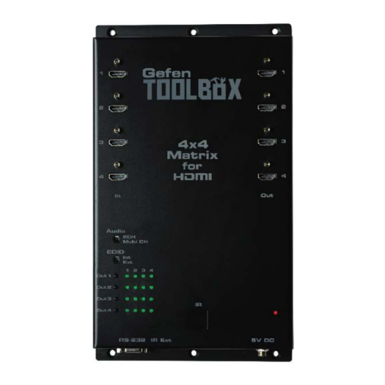
PANEL LAYOUT Front Panel Side Panel... -
Page 8: Panel Descriptions
PANEL DESCRIPTIONS HDMI Input Ports 1-4 Connect HDMI-compliant source device(s) to any of these input ports. Audio Channel Selection Switch This switch will modify the EDID to specify the number of supported audio channels when using the INTERNAL EDID mode. This setting will not affect the EDID information when using the EXTERNAL EDID mode. -
Page 9: Connecting And Operating The Gefentoolbox 4X4 Matrix For Hdmi
CONNECTING AND OPERATING THE GEFENTOOLBOX 4X4 MATRIX FOR HDMI 1.3 How to Connect the GefenToolBox 4x4 Matrix for HDMI 1.3 Use one of the provided HDMI cables to connect the source device to the HDMI input port of the GefenToolBox 4x4 Matrix for HDMI 1.3. Use additional HDMI cables to connect up to 4 HDMI cables to the four (4) displays. - Page 10 CONNECTING AND OPERATING THE GEFENTOOLBOX 4X4 MATRIX FOR HDMI 1.3 Once the LED under Input 2 turns bright blue, a picture will be displayed on the display connected to Out 3 on the Matrix. Note that in Fig 1.1, Out 1, Out 2, and Out 4 have also been routed. In this case, the displays connected to HDMI Out 1, HDMI Out 2, and HDMI Out 3 are receiving video from the source connected to HDMI In 1.
-
Page 11: Rmt-16Ir Remote Description
RMT-16IR REMOTE DESCRIPTION LED Button Press Indicator This LED will activate momentarily upon each button press. This visual indicator is to inform the user that a command has been sent by the IR remote control. Display and Source Selection Buttons These buttons will be used to send display and source selections to the GefenToolBox 4x4 Matrix for HDMI 1.3. - Page 12 RMT-16IR REMOTE DESCRIPTION The RMT-16IR remote control will allow the user to select which source will be routed to which output. Each of the four (4) outputs are assigned a group of four buttons which correspond to the four source inputs. Please use the information below when selecting the desired source for each display.
-
Page 13: Rmt-16Ir Remote Installation
RMT-16IR REMOTE INSTALLATION Installing the IR Remote Control Battery Remove the battery cover on the back of the IR Remote Control unit. Insert the included battery into the open battery slot. The positive (+) side of the battery should be facing up. Replace the battery cover. -
Page 14: Rmt-16Ir Remote Confi Guration
RMT-16IR REMOTE CONFIGURATION Resolving IR Code Confl icts In the event that IR commands from other remote controls confl ict with the supplied IR remote control unit, changing the remote channel will alleviate this issue. The IR remote control unit has a bank of DIP switches for setting the remote IR channel. -
Page 15: Changing The Ir Channel
CHANGING THE IR CHANNEL How To Change The IR Channel Use the following procedure to set the proper IR channel on the Matrix. Press and hold the Out 1 button for 5 seconds to enter IR channel selection mode. The bank of blue LED indicators will now display the currently selected IR channel. -
Page 16: Ir Extender Installation
IR EXTENDER INSTALLATION Using The IR Extender An optional IR Extender (Gefen Part No. EXT-RMT-EXTIR) can be used to extend the IR capabilities of the GefenToolBox 4x4 Matrix for HDMI 1.3. One such application allows the Matrix to be hidden within or behind a cabinet (see illustration below). -
Page 17: Edid Management
EDID MANAGEMENT Understanding EDID The GefenToolBox 4x4 Matrix for HDMI 1.3 features automatic and manual EDID adjustments to maximize compatibility of all attached devices. First, it is necessary to understand EDID and what it is used for. EDID. What is it and what is it used for? Under normal circumstances, source devices will require information about a connected display device to assess what features (for instance video resolutions and audio formats) are compatible with the output device. -
Page 18: Edid Mode Selection
EDID MANAGEMENT EDID Mode Selection • EXTERNAL MODE: To use this mode, set the EDID Mode Switch on the front panel to the EXT position. In External EDID mode, the Matrix retrieves EDID data directly from each connected A/V display device. The EDID data is then compiled and a new EDID is created based on the highest-supported video resolution and audio capabilities common to all displays. -
Page 19: Audio Channel Selection
EDID MANAGEMENT Audio Channel Selection The GefenToolBox 4x4 Matrix for HDMI 1.3 features a switch that will modify the supported audio formats listed in the pre-programmed EDID. This feature is useful for limiting the output of the source device to either 2 or multi-channel audio formats. -
Page 20: External Edid Management
EDID MANAGEMENT External EDID Management The GefenToolBox 4x4 Matrix for HDMI 1.3 features EDID Management. Before the source can send video or audio signals to the display, the source devices reads the EDID (Extended Display Identifi cation Data) of each device connected to an output. -
Page 21: Internal Edid Specifi Cation
EDID MANAGEMENT Internal EDID Specifi cations The table below lists the settings that comprise the built-in Internal EDID data structure: Video Data Block Audio Data Block Speaker Allocation xvYCC 2-channel: 1080p@60Hz 2-channel: xvYCC 709 1080p@50Hz LPCM 2CH FL/FR xvYCC 601 1080i@60Hz (native) Multi-channel: Multi-Channel:... -
Page 22: Fast Switching Technology
FAST SWITCHING TECHNOLOGY Fast Switching Technology Fast Switching Technology (FST) is a Gefen software implementation for HDMI 1.3 products. FST was created to improve the inherited lengthy HDMI authentication process, based on the HDMI and HDCP specifi cations. FST provides quicker A/V source switching and greatly improves the overall A/V system behavior and performance when more than one HDTV display is used in the system setup. -
Page 23: Rs-232 Serial Control Interface
RS-232 SERIAL CONTROL INTERFACE This feature allows for easy integration into automated systems capable of transmitting RS-232 commands. Please use the settings below to confi gure the RS-232 port of the user’s system. Transmitting the appropriate numeric ASCII character will simulate key-presses on the EXT-RMT-16IR remote control. -
Page 24: Wall Mounting Instructions
WALL MOUNTING INSTRUCTIONS The GefenToolBox 4x4 Matrix for HDMI 1.3 should be mounted vertically in a wall or cabinet with wood/drywall screws as shown in the diagram above. There should be an inch or two of clearance between the edges of the unit and any walls or vertical surfaces to allow for enough clearance for insertion and retraction of cables at the HDMI connectors. -
Page 25: Specifications
SPECIFICATIONS Maximum Pixel Clock ................225 MHz Maximum Video Resolution ......1080p@60Hz, 1920x1200@60Hz with 12-bit Deep Color Input Video Signal ..................2V p-p Input DDC Signal ................5V p-p (TTL) HDMI Connector ........type A 19-pin female; (4) input, (4) output LED Indicators (source mapping)..............(16) blue LED Indicator (power)..................(1) red RS-232 Interface................ - Page 27 Rev D7 20600 Nordhoff St., Chatsworth CA 91311 1-800-545-6900 818-772-9100 fax: 818-772-9120 www.gefentoolbox.com support@gefentoolbox.com...
Need help?
Do you have a question about the ToolBox GTB-MHDMI1.3-444 and is the answer not in the manual?
Questions and answers