Pioneer XV-HTD520 Service Manual
Dvd/cd receiver
Hide thumbs
Also See for XV-HTD520:
- Operating instructions manual (78 pages) ,
- Service manual (113 pages)
Table of Contents
Advertisement
DVD/CD RECEIVER
XV-HTD520
THIS MANUAL IS APPLICABLE TO THE FOLLOWING MODEL(S) AND TYPE(S).
Model
XV-HTD520
KUCXJ
For details, refer to "Important symbols for good services" on the next page.
PIONEER CORPORATION
PIONEER ELECTRONICS (USA) INC. P.O. Box 1760, Long Beach, CA 90801-1760, U.S.A.
PIONEER EUROPE NV Haven 1087, Keetberglaan 1, 9120 Melsele, Belgium
PIONEER ELECTRONICS ASIACENTRE PTE. LTD. 253 Alexandra Road, #04-01, Singapore 159936
PIONEER CORPORATION 2002
DVD
TUNER
/CD
/BAND
STANDBY/ON
VIDEO
PHONES
1
Type
Power Requirement
AC120V
4-1, Meguro 1-chome, Meguro-ku, Tokyo 153-8654, Japan
TV
/AUX
4 1
¡ ¢
7
3/8
DIRECT PLAY
1
2
3
4
5
DISC SKIP
EXCHANGE
OPEN/CLOSE
STANDBY
CD MODE
DSP
DISC
1
2
3
4
5
DVD/CD RECEIVER XV-HTD520
DOWN
XV-HTD520
1
ORDER NO.
VOLUME
RRV2606
UP
Reginal restriction
Remarks
codes (Region No.)
T-ZZK MAY. 2002 printed in Japan
Advertisement
Table of Contents
Troubleshooting

Subscribe to Our Youtube Channel
Related Manuals for Pioneer XV-HTD520


Summary of Contents for Pioneer XV-HTD520
- Page 1 PIONEER CORPORATION 4-1, Meguro 1-chome, Meguro-ku, Tokyo 153-8654, Japan PIONEER ELECTRONICS (USA) INC. P.O. Box 1760, Long Beach, CA 90801-1760, U.S.A. PIONEER EUROPE NV Haven 1087, Keetberglaan 1, 9120 Melsele, Belgium PIONEER ELECTRONICS ASIACENTRE PTE. LTD. 253 Alexandra Road, #04-01, Singapore 159936 PIONEER CORPORATION 2002 T-ZZK MAY.
-
Page 2: Safty Information
PIONEER Service Manual. A subscription to, or additional copies Also test with plug reversed of, PIONEER Ser vice Manual may be obtained at a (Using AC adapter Earth nominal charge from PIONEER. plug as required) - Page 3 By following the instructions in this manual, be sure to apply the prescribed grease or glue to proper portions by the appropriate amount.For replacement parts or tools, the prescribed ones should be used. XV-HTD520...
-
Page 4: Table Of Contents
8. PANEL FACILITIES ..........111 XV-HTD520... -
Page 5: Specifications
CONDITION LAST MEMO SEARCH DVD DISP CLEAR ANGLE MONO SLEEP FL DIMMER >10 PROGRAM RANDOM REPEAT REP A–B 10/0 CD MODE AUDIO SUBTITLE SYSTEM DISP DISC 1 DISC 2 DISC 3 DISC SKIP OPEN/ SHIFT DISC 4 DISC 5 CLOSE XV-HTD520... -
Page 6: Exploded Views And Parts List
Screws adjacent to mark on product are used for disassembly. For the applying amount of lubricants or glue, follow the instructions in this manual. (In the case of no amount instructions, apply as you think it appropriate.) 2.1 PACKING FRONT XV-HTD520... - Page 7 VEM-013 FM Antenna ADH7004 AM Loop Antenna ATB7009 Operating Instructions XRE3062 (English/French) NSP 9 Warranty Card ARY7045 NSP 10 Polyethylene Bag Z21-038 (0.03 x 230 x 340) Packing Sheet AHG7010 Front Pad XHA3128 Rear Pad XHA3129 Packing Case XHD3296 XV-HTD520...
-
Page 8: Exterior
2.2 EXTERIOR Refer to "2.4 TABLE MECHANISM SECTION". 40 (1/2) 40 (2/2) Refer to "2.3 FRONT PANEL SECTION". XV-HTD520... - Page 9 EXTERIOR parts List Mark No. Description Part No. Mark No. Description Part No. Pioneer Name Plate VAM1129 DVDM Assy XWX3034 Tray Cap XAN3046 MAIN Assy XWX3055 CONNECT Assy XWX3060 • • • • • DSP Assy XWX3065 NSP 48 Energy Star Label...
-
Page 10: Front Panel Section
2.3 FRONT PANEL SECTION 14 (1/2) 14 (2/2) XV-HTD520... - Page 11 NSP 12 Front Panel Assy XXG3112 Display Panel XAK3309 Lens XAK3310 Power Cap XAK3311 Front Panel XMB3083 AEB7090 Top Frame XNG3077 Sensor Cushion XEB3026 GND Plate L XNG3079 GND Plate R XNG3085 Screw BPZ30P080FMC Screw VPZ30P100FMC Cord Clamper RNH-184 XV-HTD520...
-
Page 12: Table Mechanism Section
2.4 TABLE MECHANISM SECTION 37 (2/6 - 5/6) [Roller Cover] 37 (1/6) From 37 (6/6) DVDM CN555 [PCB Cover] Refer to "2.5 TRAVERSE MECHANISM ASSY-S". From DVDM CN2 XV-HTD520... - Page 13 Motor (TRAY) DXM1118 Flexible Cable (7P) VDA1835 Motor Pulley PNW1634 Tray Belt VEB1317 Rubber Roller VEB1318 Roller Shaft VLL1511 Slide Table VNK5060 Motor Holder ANW7252 Worm Gear VNL1881 Tray Gear VNL1882 Screw JGZ17P028FMC Screw Z39-019 CR Cushion 2 XEB3020 XV-HTD520...
-
Page 14: Traverse Mechanism Assy-S
2.5 TRAVERSE MECHANISM ASSY-S • Top View DVDM Assy XV-HTD520... - Page 15 VNL1807 Gear A VNL1808 Gear B VNL1809 Gear C VNL1810 Slider VNL1811 Gear D VNL1814 NSP 30 Magnet VYM1024 Screw JFZ17P025FZK Screw JGZ17P028FMC Screw VBA1051 Magnet Holder Assy VXX2507 Spindle Motor Assy VXX2649 Carriage Motor Assy VXX2650 Screw PBA1069 XV-HTD520...
-
Page 16: Block Diagram And Schematic Diagram
POWER (3P) (3P) CN5806 (4P) KEY0 KEY0 KEY0 J5811 J5811 (3P) (3P) CN5511 CN5802 (27P) (27P) J5806 S5801 DISC KEY (4P) REMOTE SENSOR VOLUME ASSY GRID GRID V5801 XAV3011 SEGMENT SEGMENT FL TUBE JOG ASSY CN5801 CN5509 (19P) (19P) XV-HTD520... -
Page 17: Main Assy
E-VOL STK402-240 IC3171 CN3501 CN3052 CN3404 Power Amp. (1/2) (15P) (15P) (7P) C IN (SL) (SL) (SL) (SL) SL IN 18,19 CN3405 IC3161 (7P) (2/2) CN3401 (4P) R.AMP ASSY 18,22 X5501 10MHz IC5501 PDC092A Microcomputer GRID 30-42 SEGMENT 47-65 XV-HTD520... -
Page 18: Overall Wiring Diagram
(XWZ3593) POWER CORD (XDG3007) PRIMARY ASSY (XWZ3588) FGSB ASSY SMEB ASSY (VWG2009) (VWG2048) 5CH MECH.BASE ASSY LOMB ASSY (XXA3027) (XWZ3463) POWER TRANSFORMER (XTS3061) TRSB ASSY SSRB ASSY (XWZ3461) (XWZ3462) DISC KEY ASSY (XWZ3613) DISPLAY ASSY JOG ASSY (XWZ3614) (XWZ3606) XV-HTD520... - Page 19 : FOCUS SERVO LOOP LINE TUNER : TRACKING SERVO LOOP LINE DC FAN DC FAN MODULE : SLIDER SERVO LOOP LINE MOTOR MOTOR (AXQ7228) (XXM3004) (XXM3003) 1/3 - MAIN ASSY (XWX3055) HP MIC FUNCTION KEY ASSY ASSY (XWZ3608) (XWZ3612) XV-HTD520...
-
Page 20: Trsb, Ssrb, Lomb, Smeb And Fgsb Assys
3.3 TRSB, SSRB, LOMB, SMEB and FGSB ASSYS SSRB ASSY (XWZ3462) TRSB ASSY (XWZ3461) LOMB ASSY (XWZ3463) CARRIAGE MOTOR (LOADING) : VXM1033 : The power supply is shown with the marked box. A B C XV-HTD520... - Page 21 : SLIDER SERVO LOOP LINE FGSB ASSY (VWG2009) SMEB ASSY (VWG2048) CARRRIAGE MOTOR ASSY : VXX2650 SPINDLE MOTOR ASSY : VXX2649 XV-HTD520...
-
Page 22: Dvdm Assy (1/3)
3.4 DVDM ASSY (1/3) CN31 CN202 XV-HTD520... - Page 23 : RF AUDIO SIGNAL ROUTE (AD) : AUDIO DATA SIGNAL ROUTE : FOCUS SERVO LOOP LINE : TRACKING SERVO LOOP LINE : SLIDER SERVO LOOP LINE 10 11 VNK1493 19 20 CN8902 : The power supply is shown with the marked box. XV-HTD520...
-
Page 24: Dvdm Assy (2/3)
3.5 DVDM ASSY (2/3) DVDM ASSY (XWX3034) : RF VIDEO SIGNAL ROUTE (VD) : VIDEO DATA SIGNAL ROUTE (AD) : AUDIO DATA SIGNAL ROUTE VYW3004 (VD) (VD) (AD) XV-HTD520... - Page 25 1/3, 3/3 1/3, 3/3 20MHz VNK1626 : The power supply is shown with the marked box. XV-HTD520...
-
Page 26: Dvdm Assy (3/3)
3.6 DVDM ASSY (3/3) DVDM ASSY (XWX3034) (VD) (DVD) AV-1 MPEG2 DECODER (DVD) 14 17 13 16 12 15 (AD) (VCB) XV-HTD520... - Page 27 : VIDEO DATA SIGNAL ROUTE (VCB) : VCB SIGNAL ROUTE : Y SIGNAL ROUTE : C SIGNAL ROUTE (AD) : AUDIO DATA SIGNAL ROUTE (DVD) : DVD AUDIO SIGNAL ROUTE (DVD) (DVD) (DVD) (VCB) (VCB) (V/Cb) (DVD) VNK1626 (VCB) (VCB) (VCB) (DVD) XV-HTD520...
-
Page 28: Fm/Am Tuner Module
3.7 FM/AM TUNER MODULE FM/AM TUNER MODULE (AXQ7228) FM FRONT END (FM) (FM) (FM) (FM) (FM) (AM) (AM) (AM) AM RF TUNING BLOCK (FM) (AM) OSC : 981 - 2052kHz 9k step XV-HTD520... - Page 29 : The power supply is shown with the marked box. (TX) : TUNER AUDIO SIGNAL ROUTE (AM) : AM SIGNAL ROUTE (FM) : FM SIGNAL ROUTE (AM) (TX) (FM) (TX) (TX) (TX) (FM) (FM) (TX) (AM) L201 ATE7003 XV-HTD520...
-
Page 30: Main Assy (1/3)
REPLACE ONLY WITH SAME TYPE NO. 491.400 MFD, BY LITTELFUSE INC. FOR IC5001 (AEK7004). CAUTION : FOR CONTINUED PROTECTION AGAINST RISK OF FIRE. REPLACE ONLY WITH SAME TYPE NO. 491003 MFD, BY LITTELFUSE INC. FOR IC5004 and IC5005 (AEK7015). XV-HTD520... - Page 31 2/3,3/3 2/3,3/3 2/3,3/3 DC FAN MOTOR : The power supply is shown with the marked box. XV-HTD520...
-
Page 32: Main Assy (2/3)
3.9 MAIN ASSY (2/3) MAIN ASSY (XWX3055) CN5211 CN5354 XV-HTD520... - Page 33 : DVD AUDIO SIGNAL ROUTE (TX) (DI) (SL) : DI AUDIO SIGNAL ROUTE : TX AUDIO SIGNAL ROUTE : Y SIGNAL ROUTE : SL AUDIO SIGNAL ROUTE (FL) : C SIGNAL ROUTE : FL AUDIO SIGNAL ROUTE : C AUDIO SIGNAL ROUTE XV-HTD520...
-
Page 34: Main Assy (3/3)
3.10 MAIN ASSY (3/3) MAIN ASSY (XWX3055) CN15 CN5801 CN5802 XV-HTD520... - Page 35 CN3701 For DOWNLOAD (DVD) (VCB) : DVD AUDIO SIGNAL ROUTE : VCB SIGNAL ROUTE (HP) : HP AUDIO SIGNAL ROUTE : Y SIGNAL ROUTE : TRAY POSITION SERVO LOOP LINE : C SIGNAL ROUTE : SEDO SERVO LOOP LINE XV-HTD520...
-
Page 36: Amp Assy
3.11 F. AMP ASSY F.AMP ASSY (XWZ3595) : The power supply is shown with the marked box. XV-HTD520... - Page 37 (FL) : FL AUDIO SIGNAL ROUTE (SW) : SW AUDIO SIGNAL ROUTE CN3305 XV-HTD520...
-
Page 38: Amp And Speaker Assys
3.12 R. AMP and SPEAKER ASSYS R.AMP ASSY (XWZ3599) : The power supply is shown with the marked box. XV-HTD520... - Page 39 (FL) : FL AUDIO SIGNAL ROUTE SPEAKER ASSY (SW) (XWZ3603) : SW AUDIO SIGNAL ROUTE (SL) : SL AUDIO SIGNAL ROUTE : C AUDIO SIGNAL ROUTE CN3304 XV-HTD520...
-
Page 40: Connect And B To B Assy
3.13 CONNECT and B TO B ASSY CONNECT ASSY (XWX3060) XV-HTD520... - Page 41 : AUX IN AUDIO SIGNAL ROUTE : DVD AUDIO SIGNAL ROUTE (DI) (AO) : DI AUDIO SIGNAL ROUTE : Y SIGNAL ROUTE : AUX OUT AUDIO SIGNAL ROUTE (FL) (TV) : C SIGNAL ROUTE : FL AUDIO SIGNAL ROUTE : TV AUDIO SIGNAL ROUTE XV-HTD520...
-
Page 42: Dsp Assy (1/2)
3.14 DSP ASSY (1/2) DSP ASSY (XWX3065) CN5207 : The power supply is shown with the marked box. XV-HTD520... - Page 43 (SL) (DVD) : AUDIO SIGNAL ROUTE : SL AUDIO SIGNAL ROUTE : DVD AUDIO SIGNAL ROUTE (DI) : DI AUDIO SIGNAL ROUTE : C AUDIO SIGNAL ROUTE (FL) (SW) : FL AUDIO SIGNAL ROUTE : SW AUDIO SIGNAL ROUTE XV-HTD520...
-
Page 44: Dsp Assy (2/2)
3.15 DSP ASSY (2/2) XV-HTD520... - Page 45 DSP ASSY (XWX3065) (FL) : FL AUDIO SIGNAL ROUTE (SL) : SL AUDIO SIGNAL ROUTE : C AUDIO SIGNAL ROUTE (SW) : SW AUDIO SIGNAL ROUTE XV-HTD520...
-
Page 46: Display, Jog, Disc Key, Hp Mic And Function Key Assys
DISC KEY ASSY S5806 : 5 JOG ASSY S5803 : 0 OPEN/CLOSE JOG ASSY S5807 : 4 (XWZ3614) S5801 : VOLUME S5804 : EXCHANGE S5808 : 3 DISC O P Q S5805 : DISC SKIP S5809 : 2 S5810 : 1 XV-HTD520... - Page 47 S5812 : DVD/CD STANDBY/ON S5813 : TUNER/BAND S5814 : TV/AUX FUNCTION KEY ASSY (XWZ3612) S5816 : 7 (STOP) S5817 : 6 (PLAY/PAUSE) S5818 : 4 1 : The power supply is shown with the marked box. O R S XV-HTD520...
-
Page 48: Primary And Inlet Assys
3.17 PRIMARY and INLET ASSYS CN5011 CN5012 PRIMARY ASSY (XWZ3588) XV-HTD520... - Page 49 • NOTE FOR FUSE REPLACEMENT CAUTION - FOR CONTINUED PROTECTION AGAINST RISK OF FIRE. REPLACE WITH SAME TYPE AND RATINGS ONLY. AC IN INLET ASSY (XWZ3593) XV-HTD520...
- Page 50 V: 1V/div. H: 0.2µsec/div. (Composite Video output) V: 2V/div. H: 5sec/div. V: 0.2V/div. H: 1msec/div. CLOSE OPEN DISC CHANGE IC3 - pin 41 (REGB) IC18 - pin 39 (Y output) V: 1V/div. H: 5msec/div. V: 0.2V/div. H: 5msec/div. Tray Close XV-HTD520...
- Page 51 ∗ ∗ SSCK ∗ − N.C. ∗ HP DET ∗ DIR DI ∗ TX DATA ∗ DIR ERR Note ∗ : FL drive voltage, pulse waveform of Low level is VFDP (about -31V) and High level is VDD (+5V). XV-HTD520...
-
Page 52: Pcb Connection Diagram
Symbol In PCB Symbol In Schematic Part Name Diagrams Diagrams C E B Capacitor Connector Transistor B C E SIDE A Transistor with resistor B C E Field effect SIDE B Chip Part P.C.Board transistor Resistor array 3-terminal regulator XV-HTD520... -
Page 53: Trsb, Ssrb, Lomb, Smeb, And Fgsb Assys
LOADING (XNP3042-A) (XNP3042-A) MOTOR SSRB ASSY SSRB ASSY (XNP3042-A) (XNP3042-A) SIDE B LOMB ASSY SMEB ASSY FGSB ASSY CN202 CARRIAGE R101 SPINDLE MOTOR MOTOR PC101 (VNP1722-A) (VNP1784-A) SIDE A A B C D E A B C D E XV-HTD520... -
Page 54: Dvdm Assy
4.2 DVDM ASSY SIDE A SIDE A DVDM ASSY IC23 IC11 IC15 Q121 Q101 IC21 Q103 Q5 Q102 IC18 Q109 Q107 (VNP1817-A) CN55 CN8902 XV-HTD520... - Page 55 SIDE B SIDE B CN8502 DVDM ASSY CN31 IC12 IC13 IC14 Q112 IC19 Q114 Q113 Q131 Q106 IC26 IC27 Q251 (VNP1817-A) CN15 CN8501 XV-HTD520...
-
Page 56: Main Assy
XWX3056 10.DVDL W124 9.GNDA XWX3057 8.TXR W123 XWX3058 7.GNDA W102 6.TXL XWX3059 CONTACT FR1S P 5.GNDA SIDE W101 CN5701 4.AISELB CN5011 C5741 3.AISELA 2.VA+7 1.VA-7 KN5701 W112 Binde CN5701 CN5501 CN5011 CN201 CN5807 Q5721 IC15 IC16 IC14 IC13 Q5073 XV-HTD520... - Page 57 SIDE Binder PRINTED Q5031 Q5041 SIDE 2SB1375 W404 FR1S P D5075 W405 CN5012 1.VFAC 5.LSUBAC2 2.HSUBAC1 6.FLAC1 (XNP3057-B) 3.HSUBAC2 7.FLAC2 4.LSUBAC1 CN5011 CN8503 CN5012 CN5508 DC FAN MOTOR Q5073 Q5501 Q5072 IC5001 IC5004 IC5005 IC5071 Q5031 Q5043 Q5041 Q5071 XV-HTD520...
- Page 58 2.EXP DATA 1.EXP CE CN5509 D5005 D5006 D5082 D5081 CN5011 CN5508 D5071 Q5072 Q5041 Q5031 D5075 CN8503 IC5071 CN5012 CN5508 CN5012 CN8503 CN5011 IC8521 IC8541 IC8531 Q8922 IC8901 Q5042 Q5032 IC5501 Q5051 Q5553 Q5551 Q5554 Q5552 Q5571 Q3905 Q3906 XV-HTD520...
- Page 59 3.AISELA 10.DVDL 17.VE+5.6 2.VA+7 9.GNDA 16.XAOMUTE 1.VA-7 8.TXR 15.GNDA X5701 XWX3055 XWX3056 CN5011 XWX3057 XWX3058 XWX3059 CN5209 CN5701 CN5011 CN5701 (XNP3057-B) Q3253 Q3251 IC3161 IC3152 IC3181 IC3171 IC3151 Q3252 IC3001 IC3002 905 Q3906 IC5701 Q3904 Q3903 IC3902 Q3920 Q3919 XV-HTD520...
-
Page 60: Amp Assy
W224 IC3321 R3324 W243 Q3351 Q3351 R3321 D3351 W248 Q3352 CN3053 V+BL Q3352 IC3301 Q3651 D3651 D3354 Q3651 W244 D3653 R3773 Q3772 XWZ3595 W249 XWZ3596 Q3772 XWZ3597 XWZ3598 D3771 FRONT AMP ASSY D3772 (XNP3058-B) CN3771 CN3772 DC FAN MOTOR XV-HTD520... - Page 61 D3351 Q3352 R3354 R3653 R3356 R3358 D3651 D3354 Q3651 R3655 9.GNDRSW GNDS GNDP V-BH Q3773 V-BL R3657 D3653 GNDRFL Q3776 Q3772 Q3771 GNDRFR V+BL D3778 Q3771 1.V+BH Q3774 D3771 FRONT AMP ASSY R3775 R3772 D3772 R3771 (XNP3058-B) CN3771 CN3772 XV-HTD520...
-
Page 62: Amp And Speaker Assys
4.5 R. AMP and SPEAKER ASSYS SIDE A SIDE A CN3304 CN3305 CN3405 (XNP3058-B) SPEAKER ASSY Q3813 Q3702 Q3814 IC3401 IC3322 IC3021 Q3021 IC3007 (XNP3058-B) R. AMP ASSY XV-HTD520... - Page 63 DC_DET 15.RYFS_CON D3453 Q3451 D3452 Q3401 D3551 D3454 D3012 1.VR-12 VR+12 GNDS GNDP 5.GND(12) D3033 VM+12 VD+12 D3018 VX+12 D3015 VA+12 10.VA-12 V-BL D3013 D3014 GNDRSL GNDRSR GNDRC 15.V+BL D3016 D3032 D3031 REAR AMP ASSY (XNP3058-B) R. AMP ASSY XV-HTD520...
-
Page 64: Connect And B To B Assys
R5209 (XNP3059-B) (XNP3059-B) XWZ3615 FR1S P 1.VA-7 VA+7 AISELA AISELB 5.GNDA GNDA CN5209 GNDA 10.DVDL GNDA DVDR GNDA B TO B ASSY MIC IN 15.GNDA XAOMUTE VE+56 XWZ3615 1.VD+5 GNDOPT VD+12 VIDEO 5.GNDV CN5352 GNDV SQUEEZ 10.LETTER (XNP3058-B) (XNP3058-B) XV-HTD520... -
Page 65: Dsp Assy
R3852 R3853 C3827 C3829 C3828 IC3801 C3808 C3804 IC3851 R3821 C3810 C3854 R3804 C3809 C3824 C3811 C3823 C3813 C3853 C3820 C3812 C3821 CN5503 C3822 C3816 C3817 C3807 C3852 C3815 C3818 C3806 C3819 C3814 C3805 C3855 R3809 R3813 R3851 (XNP3045-D) (XNP3045-D) XV-HTD520... -
Page 66: Display, Jog, Disc Key, Hp Mic And Function Key Assys
VA+12 IC5802 W533 W532 GNDA_MIC GNDA_MIC W531 VR5801 C5812 JA5802 JA5801 C5807 W534 (XNP3058-B) CN5501 DISPLAY ASSY CN5807 CN5807 W521 STANDBY CD MODE W519 D5809 D5803 D5801 X5901 W501 W502 W503 W504 W505 W506 W507 V5801 O R S XV-HTD520... - Page 67 CN5509 CN5511 CN5801 CN5802 CN5801 CN5802 W529 DISC1 DISC2 DISC3 DISC4 DISC5 W526 W512 W525 D5808 D5806 D5805 D5804 D5807 W515 W516 DISPLAY ASSY W514 W511 W509 XWZ3606 W510 W513 W507 XWZ3607 FR1S P V5801 (XNP3058-B) O P Q XV-HTD520...
- Page 68 DISC SKIP DISC 5 DISC 4 DISC 3 J5811 (XNP3058-B) J5811 JOG ASSY JOG ASSY XWZ3614 1.GNDD KEY0 3.GNDD J5806 J5806 (XNP3058-B) DISPLAY ASSY CN5802 CN5801 CN5802 CN5807 CN5801 CN5806 GNDD VD+5 KEY0 IC5801 Q5803 Q5804 O P Q XV-HTD520...
- Page 69 2.GNDD XWZ3610 3.LOUT XWZ3611 4.GNDA_HP FR1S P 5.ROUT 6.HP DET 7.VA+12 8.GNDA_MIC (XNP3058-B) CN5807 CN5803 DISPLAY ASSY KEY1 CN5802 XWZ3606 GNDD CN5807 LOUT XWZ3607 FR1S P GNDA_HP ROUT HP DET CN5807 VA+12 GNDA_MIC MIC_IN (XNP3058-B) Q5802 O R S XV-HTD520...
-
Page 70: Primary And Inlet Assys
4.9 PRIMARY and INLET ASSYS SIDE A SIDE A PRIMARY ASSY INLET ASSY AC IN (XNP3058-B) IC41 (XNP3058-B) CN8503 XV-HTD520... -
Page 71: Primary Assy
SIDE B SIDE B PRIMARY ASSY INLET ASSY (XNP3058-B) (XNP3058-B) XV-HTD520... -
Page 72: Fm/Am Tuner Module
4.10 FM/AM TUNER MODULE SIDE A SIDE B FM/AM TUNER MODULE SIDE A CN5701 CN201 (ANP7338-B) Q202 FM/AM TUNER MODULE SIDE B (ANP7338-B) Q201 IC201 Q203 Q205 IC202 Q204 XV-HTD520... -
Page 73: Pcb Parts List
SEMICONDUCTORS IC5, IC7 BA4510F OTHERS IC21 BU2288FV CN12 7P FFC CONNECTOR VKN1211 IC14 KM68V1000CLT-7L CN11 8P FFC CONNECTOR VKN1268 LA9701M LC78652W SSRB ASSY M56788FP SEMICONDUCTORS IC19 MB811171622A-100FN 2SC2412K IC18 MB86373B DTC124EK IC15 MN414800CSJ-07 PC21 GP2S28 IC11 PD3410A PC22 RPI-574 XV-HTD520... - Page 74 C611, C612, C614, C617, C619 CKSRYB104K25 C206 CCSRCH100D50 C212, C213, C226, C233–C235 CCSRCH101J50 C705, C707, C709, C710 CKSRYB104K25 C240 CCSRCH101J50 C713, C714, C722, C724, C804 CKSRYB104K25 C231, C232 CCSRCH150J50 C807, C809, C811, C812 CKSRYB104K25 C223 CEAT100M50 C814, C815, C817, C819, C821 CKSRYB104K25 XV-HTD520...
- Page 75 C5502, C5503, C5525, C8521, C8523 CKSRYB104K25 > Q5072 2SA965 Q5043, Q5071 2SB1237X C8533, C8543, C8905, C8906, C8915 CKSRYB104K25 > Q5031, Q5041 2SB1375 C3911, C3912 CKSRYB221K50 Q5032, Q5042, Q5572 2SC2412K C3163, C3164, C3171 CKSRYB332K50 > Q5073 2SD1859X C5079, C5080, C5512, C5519, C8532 CKSRYB473K25 XV-HTD520...
- Page 76 2SC2240 Q3701 2SD1858X Q3811, Q3812, Q3819 DTC143EK Q3301, Q3302, Q3603 2SD2114K D3013–D3018, D3031–D3033 11ES2 Q3772 2SD2144S D3022, D3451–D3454, D3551, D3553 1SS133 D3703 DAN217 Q3771 DTA124EK D3021 MTZJ15B Q3773 DTA124TK Q3703 DTA143EK MTZJ5.1B Q3705 DTC123TK Q3774 DTC124EK COILS AND FILTERS XV-HTD520...
- Page 77 F5101 CHIP SOLID INDUCTOR VTF1096 C8721, C8722, C8733 CCSRCH820J50 L5379 CHIP BEADS VTL1087 C8711, C8712, C8723, C8724, C8735 CEAL100M16 L5201, L5202, L5205, L5207, L5208 VTL1112 C8741, C8743, C8744, C8761 CEAL100M16 L5211, L5271, L5272, L5280 VTL1112 C8763–C8765 CEAL100M16 CHIP BEADS XV-HTD520...
-
Page 78: Display Assy
3P CABLE HOLDER 51048-0300 OTHERS J 5805 3P JUMPER WIRE D20PYY0305E CN5807 4P CONNECTOR 52044-0445 CN5801 19P CONNECTOR 52044-1945 CN5802 27P FFC CONNECTOR 52044-2745 PRIMARY ASSY CN5806 4PJUMPER CONNECTOR 52151-0410 SEMICONDUCTORS CN5803 9PJUMPER CONNECTOR 52151-0910 > IC41 NJM78M56FA 2SD1859X XV-HTD520... - Page 79 Other Resistors RD1/4PU###J OTHERS 4P CABLE HOLDER 51048-0400 > CN1 2P VH CONNECTOR B2P3-VH J 13 5P JUMPER WIRE D20PYY0420E PCB BINDER VEF1040 SCREW PLATE VNE1948 INLET ASSY OTHERS H1, H2 FUSE CLIP AKR7001 > AN1 AC INLET 1P XKP3042 XV-HTD520...
-
Page 80: Adjustment
Pin 21 and Pin 23 of IC201 (Test point Vtm) Adjustment gets within 0 ± 50mV. MPX SG FM SG PRODUCT Voltmeter FM75Ω antenna terminal Fig.1 Adjustment Wiring Diagram FM/AM TUNER MODULE L201 IC201 pin 21 pin 23 SIDE B Fig.2 Adjustment Point XV-HTD520... -
Page 81: General Information
When a DVD disc is played in the test mode, this function is effective. This function is effective only for DVD pickup (650nm). Character in bold : Item name : Information display Laser diode current value Test Mode Screen Display XV-HTD520... -
Page 82: Test Points Location
7.1.2 TEST POINTS LOCATION DVDM ASSY Front Side VCODR IC13 IC14 C707 SREQ TP3 (TE) IC19 TP1 (FE) VREF TP2 (RFO) IC27 IC26 VREF TP4 (FDO) R389 Short-circuit at diagnosis CN15 SIDE B XV-HTD520... -
Page 83: Test Mode Screen Display
AGC on [AGC-ON] (4) Background color indication [C – R∗ ∗ G∗ ∗ B∗ ∗] AGC off [AGC-OFF] (5) 1 Tracking status [TRKG – ∗∗∗] Tracking on [ON ] Tracking off [OFF] 2 Laser diode current value [LDI – ∗∗∗] XV-HTD520... - Page 84 [∗ ∗ ∗ ∗ ∗ ∗ / ∗ ∗ ∗ ∗ ∗ ∗ ∗] 1 Part number of the flash ROM <Front> (Example) VYW1536-A = W1536A (Example) PD6256A9 = 6256A9 2 Part number of the system controller <Rear> (Example) PD3381T1 = 3381T1 XV-HTD520...
-
Page 85: Power On Sequence
* If the pulse is not input to the AC terminal (Pin 26) about 60ms, during the memory backup mode, the microcomputer does not process all. * It returns from the memory backup mode when there is a rising up input at the XRESET terminal (Pin 11). XV-HTD520... -
Page 86: Trouble Shooting
• It is recognized that other KEY has already • When KEY is not pushed, whether KEY input all. terminal (18Pin, 22Pin) is 5V is confirmed. If the KEY input terminal is not 5V, whether KEY SW on the line breaks is confirmed. XV-HTD520... -
Page 87: Error Code
No FOK pulse return to its position where the during When the focus was deviated continuously 20 times. error was generated (for 3 playback CLVA times),then opens. If the same error persists after one retry, the tray opens. (No FOK pulse) XV-HTD520... - Page 88 A command could not be sent because ABUSY was Auto sequence Stop low. ABUSY did not return within 200 mS after TLV already busy command was sent. Pause mode could not be restored within three retries 62 Pause retry error Continues operation after it had been released. XV-HTD520...
- Page 89 (1) Focus ON sequence could not be completed even if more than two seconds after then opens (stops in the the focus ON command (to the servo DSP) was sent. case of side B). (2) Focus IN sequence was finished, actually focus IN was not completed. XV-HTD520...
- Page 90 Operation of the Unit AV1 access error bit3=1 08 etc. (read, write NG) No operation or it becomes debugging indication if the power is able to ON. bit2=1 04 etc. MY CHIP access error bit1=1 01 etc. SRAM access error XV-HTD520...
-
Page 91: Disassembly
Remove the DVDM Assy (Connectors × 2) Put the Power Cord in the outlet Power On → Tray close (Automatically) PCB Support Press the EXCHANGE Button (clamp the Test Disc → Tray Open) Cutting Pliers Test Disc CN15 DVDM Assy Diagnosis XV-HTD520... - Page 92 Unhook Unhook Unhook Unhook Unhook × 2 × 2 Unhook Unhook DISPLAY Assy HP MIC FUNCTION KEY DISC KEY JOG Assy Remove two Screws Assy Assy Assy Put the Power Cord in the outlet Power ON Front Frame Diagnosis XV-HTD520...
- Page 93 Remove three Flexible Cables and Connector Assy MAIN Assy Remove five Screws Remove four Screws CN8903 CN555 Remove four Screws Front Frame ×2 ×3 ×2 DVDM Assy DVDM Assy Remove the Table Mechanism Section Table Mechanim Section MAIN Assy XV-HTD520...
- Page 94 MAIN Assy Diagnosis How to Open the Tray by Manual Operating Gear Pulley Front Frame Rear Panel Tray Open Chassis Gear Pulley If the tray moved toward the front about 2 or 3 cm, pull out the tray by hands. XV-HTD520...
- Page 95 In that case, set the tray in the following procedures. Remove Tighten Note : Do not need to match with Disc No. (1 to 5) when returns the tray. Detect it automatically. Set the tray to the position Rotary Tray that can see a hole of the center. XV-HTD520...
- Page 96 • Bottom View ×4 Release ×2 SMEB Assy FFC Holder Flexible Cable (24P) Mechanism Base Section CN202 Pickup One Screw Flexible Cable (8P) Connector Mecha Frame ×2 Unhook Traverse Mechanism Assy-S Clamper Holder Unhook Unhook One Screw Spring Exchange XV-HTD520...
- Page 97 One Screw • Bottom View Reference Hook ×2 Styling of the Flexible Cables SMEB Assy FFC Holder Flexible Cable (24P) 24P Flexible Cable CN202 8P Flexible Cable Leave slacking of two flexible cables Pickup One Screw Flexible Cable (8P) Connector XV-HTD520...
- Page 98 Change Gear Planet Base Connect four connectors. Match it between first teeth of the gear. MAIN Assy CN8903 CN555 DVDM Assy When the tooth of gear deviates more than two or three tooth, Strange sound is generated, and cause trouble. XV-HTD520...
- Page 99 Clamper Holder Hook Spring ×4 Mechanism Base Section Mecha Frame XV-HTD520...
- Page 100 Bring an extra flexible cable close to the front side. Tray Section Mechanism Base Section CN12 TRSB Assy Flexible cable Flexible cable from from SSRB Assy CN21 SSRB Assy CN21 Tray Section Assemble the Front Panel Section. Assemble the Bonnet. (Screws × 11) XV-HTD520...
- Page 101 Important Points when Assembling the Mechanism Section Clamper Plate Tray Gear Motor (for Tray) Motor Pulley (for Tray Motor) Motor Holder Worm Gear, Tray Belt Motor (for Loading) Motor Pulley (for Loading Motor) XV-HTD520...
- Page 102 Motor Holder Apply Lubricating Oil (GYA1001) to the holder part. Motor Holder Apply Lubricating Oil (GYA1001) Motor (for Loading), Motor Pulley (for Loading Motor) Adjust the height of Motor Pulley to 6.2mm. Motor Pulley 6.2mm Motor Apply Lubricating Oil (GYA1001) XV-HTD520...
-
Page 103: Trouble Shooting For Mechanism Section
Disc Clamp Detect SW (S11 : VSK1011) Tray position Detect Sensor (PC22 : RPI-574) Disc Detect Sensor (PC21 : GP2S28) Open Open Close Close Motor : DXM1118 Tray Open/Close (for Rotary Tray Drive) Position Detect SW (S21 : VSK1011) XV-HTD520... - Page 104 Damage of Worm Gear or grease is When Rotary Tray turns, hear the rattle and large sound. insufficient. Disc Detect Sensor (PC21) is damage or Playback even if indicates it with "NO DISC". contact defectiveness, etc.. Take time till playbacks. XV-HTD520...
- Page 105 Worm Gear : VNL1881 Tray position Detect Sensor (PC22 : RPI-574) Disc Detect Sensor (PC21 : GP2S28) Motor : DXM1118 Tray Open/Close (for Rotary Tray Drive) Position Detect SW (S21 : VSK1011) Flexible Cable (7P) : VDA1835 (TRSB CN12 ↔ SSRB CN21) XV-HTD520...
-
Page 106: Parts
75 OHM C-IN C.OUT2 AMP/LPF DRIVER CLAMP GND1 GND2B 4.25V 75 OHM VREF C.OUT1 DRIVER TO PEDESTAL CLAMP C_OFFSET VCC1 C-DC.OUT DC_CTL SYNC 75 OHM CLAMP Y.IN Y.OUT2 DRIVER AMP.SW 2 STEP GND2C AMP/LPF 75 OHM PNP-B-IN Y.OUT1 DRIVER XV-HTD520... - Page 107 PDC092A (MAIN ASSY : IC5501) • Microcomputer IC • Pin Function − − l l i − − − − XV-HTD520...
- Page 108 − Vacuum Fluorescence Display Power VFDP − − l l i X CENTRE MUTE Centre Chunnel Audio Mute − − − -− XV-HTD520...
-
Page 109: Display
P1 NX NX NX NX NX NX NX NX NX NX NX NX NX NX NX NX NX NX NX (5) 1G to 13G : Grid Pin No. Connection NX NX NX 13G 12G 11G 10G 9G 8G 7G 6G 5G 3G 2G 1G NP NP XV-HTD520... -
Page 110: Cleaning
Before shipping out the product, be sure to clean the following positions by using the prescribed cleaning tools: Position to be cleaned Cleaning tools Pickup leneses Cleaning liquid : GEM1004 Cleaning paper : GED-008 Position to be cleaned Cleaning tools Fans Cleaning paper : GED-008 XV-HTD520... -
Page 111: Panel Facilities
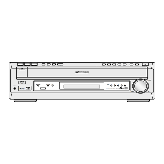
DISC SKIP EXCHANGE DIRECT PLAY OPEN/CLOSE STANDBY/ON VOLUME VIDEO STANDBY CD MODE DISC PHONES DVD/CD RECEIVER XV-HTD520 DOWN DVD/CD TUNER/BAND TV/AUX (/DIGITAL IN) ¡ ¢ Disc tray Disc buttons 10 DISC SKIP 11 EXCHANGE 12 0 OPEN/CLOSE 13 PHONES Plug in a pair of headphones here. -
Page 112: Rear Panel
14 Character display When playing discs : Left to Tuned indicator right displays disc number, title, chapter/track, FM stereo indicator minutes, seconds. FM mono indicator 15 RANDOM MIDNIGHT 16 REPEAT 10 CONDITION 17 DISC | ALL DISCS Indicates the random or repeat mode. XV-HTD520... - Page 113 47 SHIFT Hold down to access secondary button 11 DVD SETUP functions 12 Cursor up Use for navigating menus and on- 48 DISC 4 screen displays. 49 DISC 5 13 SYSTEM SETUP 50 OPEN/CLOSE 0 14 Cursor left Use for navigating menus and on- screen displays. XV-HTD520...
Need help?
Do you have a question about the XV-HTD520 and is the answer not in the manual?
Questions and answers