Table of Contents
Advertisement
Quick Links
DVD/CD RECEIVER
XV-HA5
THIS MANUAL IS APPLICABLE TO THE FOLLOWING MODEL(S) AND TYPE(S).
Model
Type
XV-HA5
WLXJ
XV-HA5
XV-HA5
NTXJ
For details, refer to "Important Check Points for Good Servicing".
PIONEER CORPORATION
PIONEER ELECTRONICS (USA) INC. P.O. Box 1760, Long Beach, CA 90801-1760, U.S.A.
PIONEER EUROPE NV Haven 1087, Keetberglaan 1, 9120 Melsele, Belgium
PIONEER ELECTRONICS ASIACENTRE PTE. LTD. 253 Alexandra Road, #04-01, Singapore 159936
PIONEER CORPORATION 2005
Power Requirement
AC220-240V
AC110V
AC220V
4-1, Meguro 1-chome, Meguro-ku, Tokyo 153-8654, Japan
STANDBY/ON
KARAOKE
DVD/CD
INPUT
FM/AM
VOLUME
+
TIMER
DVD/CD
-
STEREO DVD RECEIVER
HA5DVD
MIC
PHONES
INPUT
MIN
MAX
VOL
MAIN
SUB
F. AUDIO
USB
XV-HA5
Regional restriction
codes (Region No.)
3
3
3
ORDER NO.
RRV3217
Remarks
T-ZZR AUG. 2005 printed in Japan
Advertisement
Table of Contents

Related Manuals for Pioneer XV-HA5


Summary of Contents for Pioneer XV-HA5
- Page 1 PIONEER CORPORATION 4-1, Meguro 1-chome, Meguro-ku, Tokyo 153-8654, Japan PIONEER ELECTRONICS (USA) INC. P.O. Box 1760, Long Beach, CA 90801-1760, U.S.A. PIONEER EUROPE NV Haven 1087, Keetberglaan 1, 9120 Melsele, Belgium PIONEER ELECTRONICS ASIACENTRE PTE. LTD. 253 Alexandra Road, #04-01, Singapore 159936 PIONEER CORPORATION 2005 T-ZZR AUG.
-
Page 2: Safety Information
The interlock mechanism mentioned above becomes invalid in this mode. 2. When the cover is open, close viewing through the objective lens with the naked eye will cause exposure to the laser beam. ∗ : Refer to page 63. XV-HA5... - Page 3 To protect products from damages or failures during transit, the shipping mode should be set or the shipping screws should be installed before shipment. Please be sure to follow this method especially if it is specified in this manual. XV-HA5...
-
Page 4: Table Of Contents
7.1.9 ID NUMBER AND ID DATA SETTING ....................76 7.1.10 SEQUENCE AFTER POWER ON/0FF ................... 79 7.1.11 SYSTEM COMPUTER PROTECT SPECIFICATION ..............83 7.1.12 PROTECTION CIRCUIT........................86 7.1.13 DISASSEMBLY..........................88 7.2 PARTS..............................100 7.2.1 IC ..............................100 7.2.2 DISPLY ............................105 8. PANEL FACILITIES ............................106 XV-HA5... -
Page 5: Specifications
Non-skid pads ......8 CLEAR ENTER • Dry Cell Batteries PQRS WXYZ MARK Note REPEAT RANDOM PROGRAM DISP/CHARA KARAOKE ECHO KEY CONTROL • Specifications and design subject to possible modification without notice, due to improvements. XV-HA5... -
Page 6: Exploded Views And Parts List
Screws adjacent to mark on product are used for disassembly. For the applying amount of lubricants or glue, follow the instructions in this manual. (In the case of no amount instructions, apply as you think it appropriate.) 2.1 PACKING XV-HA5 XV-HA5... - Page 7 Dry Cell Batteries(R6P,AA) VEM1031 NSP 9 Warranty Card See Contrast table(2) NSP 10 Vinyl Bag See Contrast table(2) (2) CONTRAST TABLE XV-HA5/WLXJ, LFXJ and XV-HA5/NTXJ are constructed the same except for the following: XV-HA5 XV-HA5 XV-HA5 Mark No. Description /WLXJ /LFXJ /NTXJ...
-
Page 8: Exterior Section
2.2 EXTERIOR SECTION To "2.3 FRONT PANEL SECTION NON-CONTACT SIDE CONTACT SIDE Refer to "2.3 FRONT PANEL SECTION" Cleaning paper GED-008 Refer to "2.4 05 LOADER ASSY" XV-HA5... - Page 9 Screw XBA3015 Rear Panel HAL See Contrast table (2) Screw BPZ30P080FNI Mecha Frame XNG3136 (2) CONTRAST TABLE XV-HA5/WLXJ, LFXJ and XV-HA5/NTXJ are constructed the same except for the following: XV-HA5 XV-HA5 XV-HA5 Mark No. Description /WLXJ /LFXJ /NTXJ IF Assy...
-
Page 10: Front Panel Section
2.3 FRONT PANEL SECTION NON-CONTACT SIDE CONTACT SIDE To "2.2 EXTERIOR SECTION To "2.2 EXTERIOR SECTION XV-HA5... - Page 11 HP2 Assy XWZ4035 13P FFC/30V XDD3171 29P FFC/30V XDD3173 Door Spring XNG3138 Gnd Plate B XNG3140 AEB7090 Pioneer Name Plate AAM7012 Func Button A XAD3219 Func Button B XAD3222 Tray Cap XAK3491 Standby Button Assy XXG3212 Front Panel Assy XXG3215...
-
Page 12: Loader Assy
JGZ17P028FTC Flexible Cable (24P) VDA2008 Screw VBA1094 Connector Assy 2P VKP2253 Tray VNL1920 Floating Rubber VEB1351 Clamp Magnet VMG1029 Belt VEB1358 Stabilizer VNE2253 Loading Base VNL1917 Float Base 04 VNL1968 Drive Cam VNL1919 Gear Pulley VNL1921 Loading Gear VNL1922 XV-HA5... - Page 13 Rear View Daifree Daifree No. 23 No. 23 GEM1036 GEM1036 Tray Tray Concave of unevenness Concave of unevenness Inner side of a ditch Daifree GEM1036 Top View Bottom View Side of the rib Concave of unevenness Daifree Daifree GEM1036 GEM1036 XV-HA5...
-
Page 14: Traverse Mechanism Assy-S
Skew Screw VK1 DBA1211 Guide Shaft VK1 DLA1940 Sub Guide Shaft VK1 DLA1941 Skew Spring VK1 DBH1516 NSP 5 Joint VK1B DNK4272 NSP 12 Stepping Screw DBA1205 Spindle Screw VK1(for Service) DBA1252 Joint Spring VK1 DBK1235 Stepping Motor VK1 DXM1201 XV-HA5... - Page 15 XV-HA5...
-
Page 16: Block Diagram And Schematic Diagram
-6 dB ATT FRONT IN DETECT (15P) (29P) (u-p) (u-p) TUNER USB IN RECEIVER CN5951 (2/2) IC5201 HP2 ASSY CN5421 (29P) PCM 2900EG (1/2) DISP ASSY (15P) TUNER MODULE TUNER MODULE TUNER AXA7173 CN5701 (11P) REC MUTE (u-p) LINE OUT XV-HA5... -
Page 17: Amp Section
HA17558AF (5P) (11P) (15P) (15P) (11P) -SFC SYSTEM MUTE (u-p) LOW POWER AMP XPROTECT MODULE (u-p) SECONDARY ASSY ANALOG AUDIO & VIDEO SIGNAL DIGITAL AUDIO SIGNAL CONTROL SIGNAL IF ASSY • R ch is same as L ch. OTHER XV-HA5... -
Page 18: Overall Wiring Connection Diagram
HPDET HPDET GNDC GNDC JA9901 AKN7005 VBUS VBUS JA9401 (MAIN) AKN7005 2mm PITCH WIRE JA9402 (SUB) AKN7005 1/2, 2/2, IF ASSY (XWZ4033:XV-HA5/WL) (XWZ4049:XV-HA5/LF) (XWZ4050:XV-HA5/NT) CN3101 CN8301 XKP3070- XKP3081- LOUT LOUT GNDA GNDA ROUT ROUT GNDA GNDA DVDR DVDR GNDA GNDA... - Page 19 MUTE MUTE VP+15 VP+15 GNDP GNDP 11 12 13 14 BtoB BtoB BtoB 2.5mm pitch 2.5mm pitch 2.5mm pitch 10 11 12 13 14 REGULATOR ASSY POWER ASSY (XWZ4039) (XWZ4040) CN3651 SYS U-COM DOWNLOAD KM200SA2L LOW POWER AMP ASSY XV-HA5...
-
Page 20: Dvdm Assy (1/2)
: TRACKING SERVO LOOP LINE : STEPPING SERVO LOOP LINE (C/V) : VIDEO SIGNAL ROUTE (R/Cr) : VIDEO SIGNAL ROUTE(R/Cr) AYW7069 (G/Y) : VIDEO SIGNAL ROUTE(G/Y) (B/Cb) : VIDEO SIGNAL ROUTE(B/Cb) (S_Y) : S VIDEO SIGNAL ROUTE (S_C) : S VIDEO SIGNAL ROUTE XV-HA5... - Page 21 DVDM ASSY (AWM7966) MT1389FE/C2-L XV-HA5...
-
Page 22: Dvdm Assy (2/2)
3.4 DVDM ASSY (2/2) DVDM ASSY (AWM7966) XV-HA5... - Page 23 6.4V Video Driver Amp (S_C) (S_C) (C/V) (C_Y) (C/V) (S_Y) (Cb) (Cr) (Cb) (Cr) R521 R522 DAC 2CH : AUDIO SIGNAL ROUTE (C/V) : VIDEO SIGNAL ROUTE (S_Y) : S VIDEO SIGNAL ROUTE (S_C) : S VIDEO SIGNAL ROUTE XV-HA5...
-
Page 24: If Assy (1/2)
ALL RESISTORS ARE IN Ω GLED ALL CAPACITORS ARE IN µF CN43 1/2W RD1/2PM* UNLESS OTHERWISE SPECIFIED 52147-1210 1/16W(CHIP) CH :CCSRCH (OTHER :CKSRYB) ALL INDUCTORS ARE IN µH PCB Binder PCB Binder :CEAL VEF1040- VEF1040- GNDM GNDU LCYA :CEAT XV-HA5... - Page 25 :USB LCH Audio SIGNAL ROUTE GNDP (FL) (USBL) CN42 :LINE Lch AUDIO SIGNAL ROUTE :FA LCH AUDIO SIGNAL ROUTE (FAL) (LINEL) 52147-1110 :TX Lch AUDIO SIGNAL ROUTE :LINE OUT LCH AUDIO SIGNAL ROUTE (LINEOUT L) (TXL) :MD Lch AUDIO SIGNAL ROUTE (MDL) XV-HA5...
-
Page 26: If (2/2) And Disp Assys
D3953 DAN202K- AC PULSE XHPMUTE R5803 RECMUTE RT1N431M 2SC4081(QR) 2.2K C5805 R3934 R5806 R5804 10/50 Q3951 2SA1576A(QR) D3001 Q5803 XRECMUTE Q5802 Q3003 +4.9V RT1P241M 1SS355 UN+56 +5.6V GNDU VA-12 GNDU D511 1SS355 AUDIO SYSPOW Q5804 R5808 STBY IC511 BA178M05FP XV-HA5... - Page 27 2.2/50 (USBL) (2/2) GNDD USBL R3198 GNDD C3196 VDET 330p C3195 330p GNDD R3197 U-COM (1/2) R3191 C3191 IC3191 2.2/50 :FLch AUDIO SIGNAL ROUTE (USBL) :USB LCH Audio SIGNAL ROUTE (FL) HA17558AF VA-7 :FA LCH AUDIO SIGNAL ROUTE (FAL) XV-HA5...
-
Page 28: Hp 2 Assy
STBY R9954 (FL) R9957 STBY L9952 STBY R9952 JA9902 AKN7005- R9956 STBY KN9901 VNF1084- GNDC R9948 FRONT AUDIO STBY R9943 L9941 R9945 STBY (FAL) STBY L9943 STBY (FAL) STBY R9947 GNDA R9944 JA9901 L9942 STBY R9946 STBY AKN7005- STBY XV-HA5... - Page 29 HA17558AF- STBY R9413 STBY R9415 2.2k R9414 C9414 1200p GNDA :FLch AUDIO SIGNAL ROUTE CN9421 (FL) 52045-1345 :FA LCH AUDIO SIGNAL ROUTE (FAL) V BUS GNDC HPDET (FL) GNDHP (FL) FADET GNDA FA L (FAL) GNDA FA R (FAL) XV-HA5...
-
Page 30: Regulator And Power Assys
D3653 D3652 D3651 VP+15 GNDPRE5 R3669 STBY H/L CONT D3655 Q3651 STBY 2SB1237X REF5V 1SR154-400 XPROTECT D3656 +11.6V FAN GND D3658 STBY R3656 R3661 D3664 D3657 D3665 R3677 Q3655 DTC114TK R3667 Q3653 2SC2412K(RS) FAN LOCK, SHORT, OPEN DETECT GNDFAN XV-HA5... - Page 31 GNDA R3312 R3313 +4.2V GNDA R3319 STBY Q3305 R3317 R3301 RT1N241M CN3302 0.47/50 KM250NA15L R3307 R3303 C3301 W126 STBY STBY STBY Q3301 STBY STBY STBY R3304 Q3303 STBY R3320 GNDA STBY Q3302 C3302 R3302 0.47/50 R3318 :AUDIO SIGNAL ROUTE XV-HA5...
-
Page 32: Secondary And Primary Assys
SENSE (VP+15V) 39k(F) REF5V CN3301 (1/2)CN42 (1/2)CN43 MUTE STBY GNDA GNDA NOTES ALL CAPACITORS ARE IN µF UNLESS OTHERWISE SPECIFIED CH :CCSRCH (OTHER :CKSRYB) :CEAL :CQMA :CEAT ALL RESISTORS ARE IN Ω 1/16W(CHIP) ALL INDUCTORS ARE IN µH LCYA XV-HA5... - Page 33 800mA/250V 1.6A/250V (REK1021)/J (REK1024)/J * FU2 5A/250V 5A/250V (REK1029)/J (REK1029)/J GNDM GNDD * T1 ATT7080- ATT7080- * T2 ATS3098 XTS3098 XTF3003- XTF3003- * L1 * C25 0.033/250V * C45 0.033/250V :AUDIO SIGNAL ROUTE :DVD Lch AUDIO SIGNAL ROUTE (DVDL) XV-HA5...
-
Page 34: Karaoke Assy
GNDD NoAssign1 GNDD GNDD ASPECT GNDC VSEL1 VSEL2 SQUEEZE P/XI CN8502 VKN1258- NOTES ALL CAPACITORS ARE IN µF UNLESS OTHERWISE SPECIFIED CH :CCSRCH (OTHER :CKSRYB) :CEAL :CEAT ALL RESISTORS ARE IN Ω 1/16W(CHIP) ALL INDUCTORS ARE IN µH LCYA XV-HA5... - Page 35 STBY C8210 0.22 ADINT IN CLKO ADINT OUT C8214 KEYUP 0.22 DAINT IN KEYDOWN C8209 0.068 DAINT OUT DACCONT2 C8208 0.068 Q8402 MODE1 DACCONT1 C8433 C8207 0.068 2SJ103(GR) VA+12 MODE2 ADCONT 0.22/50 R8432 M65847AFP- CN5105 52147-0410 HP2 ASSY J9911 XV-HA5...
-
Page 36: Waveforms
IC201-pin225 [ASPDIF AUDIO DIGITAL SIGNAL] [SPINDLE (WVU)] V: 2V/div. H: 500nsec/div. V: 2V/div. H: 2msec/div. IC401-pin23 [CompositeVideo Out] IC401-pin21 [S VIDEO OUT - Y] V: 1V/div. H: 10µsec/div. V: 1V/div. H: 10µsec/div. IC401-pin26 [S VIDEO OUT - C] V: 1V/div. H: 10µsec/div. XV-HA5... - Page 37 V: 2V/div. H: 100us/div. V: 2V/div. H: 100us/div. V: 2V/div. H: 100us/div. V: 2V/div. H: 100us/div. [TUNER] [TUNER] IC5201-pin 1 [D+] IC5201-pin 2 [D-] DISP ASSY V: 2V/div. H: 500us/div. V: 2V/div. H: 500us/div. [USB (At connecting PC)] USB Interface data waveform XV-HA5...
- Page 38 XV-HA5...
-
Page 39: Pcb Connection Diagram
Resistor array 3-terminal regulator 4.1 LOAB ASSY SIDE A SIDE B LOAB ASSY LOAB ASSY VNP1836-C LOAB PNE-1B1 S101 LOAD+ VWG2279- CN602 CN602 C102 LOAD- VWG2346- C101 CN601 (VNP1836-C) (VNP1836-C) CN601 CN602 CN601 CN601 CN602 CN104 LOADING MOTOR ASSY XV-HA5... -
Page 40: Dvdm Assy
Q304 IC761 Q305 Q562 IC751 Q564 IC101 IC731 Q565 Q561 Q881 Q308 Q533 Q534 Q731 Q801 Q307 IC531 Q535 Q532 Q531 IC711 Q506 Q503 Q504 IC591 IC501 IC204 Q502 Q501 Q401 Q505 IC201 Q851 Q821 Q481 (ANP7527-A) CN104 CN601 XV-HA5... - Page 41 SIDE B SIDE B DVDM ASSY Q732 Q201 IC203 IC451 IC202 IC401 (ANP7527-A) XV-HA5...
-
Page 42: If Assy
W176 C302 W175 W174 W185 IC301 W173 IC3201 JA4602 W184 W147 JA3001 W145 IC3301 IC3911 W146 W121 IC8881 CN43 CN42 W107 49102.5 CN42 CN43 C3281 BOND CN3352 C3284 BOND W105 BOND C3283 PRODUCTION CODE BOND C3282 BOND IF ASSY XV-HA5... - Page 43 W185 X5501 W186 W192 W202 C3242 W191 VE+5 W200 IC3201 W190 W195 W199 W189 W201 W184 W165 W171 W157 W156 C3930 W155 C3241 C5805 W154 W153 C5801 (XNP3094-B) C5809 W120 CN5952 49102.5 C8885 CONTACT W119 SIDE CN43 CN5952 CN901 XV-HA5...
- Page 44 R3217 GNDHP 25.FADET C5589 R3218 26.GNDA 27.FAL 28.GNDA 29.FAR R5932 CN5951 R5933 C3251 R3041 C5510 Q5804 R5594 IC501 D3951 (XNP3094-B) IC511 Q3952 Q3003 R3936 R3010 49102.5 CAUTION CN5952 REPLACE IC LINKS AS L8881 MARKED.MFD BY LITTELFUSE INC. CN5952 CN43 XV-HA5...
- Page 45 IC3911 Q3901 IC501 Q3953 Q5801 R3009 L3009 Q3001 Q3951 ROUT Q5952 IC511 Q3003 R3225 CN43 CN42 Q5803 Q3221 CN43 CN42 IF ASSY XWZ4030 XWZ4049 XWZ4033 0 1 2 3 0 1 2 3 4 5 6 7 8 9 XV-HA5...
-
Page 46: Disp Assy
CONTACT UPPER SIDE CONTACT CN5921 CN5911 UPPER SIDE W625 S5964 S5963 W601 W602 W622 W603 W604 W614 W615 S5957 W616 S5955 W617 S5962 W618 S5954 W619 C5216 W620 S5961 C5215 S5953 W609 W621 C5942 S5952 S5956 S5951 D5920 (XNP3094-B) XV-HA5... - Page 47 R5215 R5216 R5217 R5942 Q5924 Q5924 R5924 R5953 D5927 R5923 Q5921 D5925 Q5921 R5956 Q5923 Q5923 R5929 Q5971 R5928 Q5971 R5927 Q5922 Q5922 R5926 R5925 C5921 R5922 R5941 R5931 R5952 R5971 Q5925 R5930 R5943 C5941 C5951 Q5925 C5922 (XNP3094-B) XV-HA5...
-
Page 48: Hp2, Regulator And Power Assys
GNDP W112 L-OUT W138 W113 GNDA W139 W114 GNDP W111 W140 W129 R-OUT GNDA W127 W141 W130 R+OUT MUTE W126 W131 OPEN SIDE OPEN SIDE G D S PRINTED SIDE (XNP3095-B) IRF9540A CN3301 CN3302 E F G CN24 CN23 XV-HA5... - Page 49 Q3654 Q3654 D3656 Q3655 Q3655 PRE5V R3658 R3670 R3666 R3665 (XNP3095-B) CN3651 CN3303 POWER ASSY Q3656 C3303 R3309 C3304 C3308 GNDA MUTE R3314 Q3304 C3309 R3313 Q3301 D3304 Q3305 Q3305 R3306 R3305 Q3302 (XNP3095-B) E F G CN3302 CN3301 XV-HA5...
-
Page 50: Secondary Assy
4.6 SECONDARY ASSY SIDE A SIDE A SECONDARY ASSY CN26 CN21 CN3303 CN22 IC31 CN24 (XNP3095-B) CN23 CN24 CN43 CN3302 CN42 CN3301 XV-HA5... - Page 51 SIDE B SIDE B SECONDARY ASSY CN21 CN22 (XNP3095-B) CN23 CN24 XV-HA5...
-
Page 52: Primary Assy
CN26 W203 STBY W204 LIVE RISK OF FIRE 115V AS MARK REPLACE FUSE W226 GNDU STBY PRIMARY SIDE 230V 115V SECONDARY PRIMARY ASSY SIDE JJ ONLY W227 W228 STBY LF ONLY W212 W219 230V W220 LF ONLY W221 (XNP3095-B) XV-HA5... - Page 53 SIDE B SIDE B PRIMARY ASSY NEUTRAL CN26 HELP SYSPOW LIVE RISK OF FIRE GNDU UN+56 REPLACE FUSE AS MARK LF/JJ PRIMARY SECONDARY PRIMARY ASSY XWZ4036 JJ ONLY XWZ4041 XWZ4044 LF ONLY LF ONLY (XNP3095-B) XV-HA5...
- Page 54 SIDE GNDA W326 Q8402 IC8401 W322 GNDA C8221 Q8201 C8222 W309 LOUT C8213 IC8301 W320 IC8201 W306 W319 VA+12 GNDA W305 FLIN W304 FRIN W303 DVDL W302 GNDA W301 DVDR W324 GNDA W325 OPEN GNDU SIDE (XNP3095-B) CN8301 CN3101 XV-HA5...
- Page 55 C8209 R8306 C8208 C8219 R8202 VA+12 C8207 R8207 C8204 C8218 GNDA R8307 R8201 R8205 FLIN C8217 FRIN R8206 C8216 C8215 DVDL C8214 GNDA C8531 R8533 R8531 DVDR GNDA R8534 C8532 R8532 GNDU (XNP3095-B) CN8301 IC8401 Q8402 IC8301 Q8201 IC8201 XV-HA5...
-
Page 56: Pcb Parts List
Although XWZ4041 and XWZ4044 are different in part number, they have the same service parts. • FM/AM TUNER UNIT This assembly has no service parts. 7 7 7 7 PCB PARTS LIST FOR XV-HA5/WLXJ UNLESS OTHER WISE NOTED Mark No. Description Part No. - Page 57 C102–C104, C121, C140, C243 CKSRYB105K10 L5801 LCYA220J2520 C282, C289, C343–C347 CKSRYB105K10 C412–C414, C711, C751, C762 CKSRYB105K10 CAPACITORS C219 CKSRYB152K50 C5801 ACH1246 C144–C146, C208, C210 CKSRYB222K50 C5510 CCSRCH100D50 C3039,C3040,C3203,C3204 CCSRCH101J50 C269 CKSRYB333K16 C3909,C3910,C5721,C5723,C5808 CCSRCH101J50 C258, C259 CKSRYB473K50 C5509 CCSRCH120J50 C255 CKSRYB474K10 XV-HA5...
- Page 58 > Q3651 2SB1237X Q5923 RT1N431M 2SC1740S Q3652-Q3654 2SC2412K D5927 1SS355 D5925 DAN217 Q3655 DTC114TK D5920 NEPW500-4A05 > IRF9530 D5921-D5923 NSPW510BS-2224 > D3656 1SR154-400 D5924 SLI-343YCW(RST) > D3651-D3654 1SS355 D3657,D3664,D3665,D71-D75 1SS355 D5901 UDZS6R8(B) 1SS355 SWITCHES AND RELAYS UDZS18(B) S5951-S5957,S5961-S5964 VSG1009 XV-HA5...
- Page 59 AN1 AC INLET 1P XKP3084 2SA1576A 2SC4081 D55,D56 1SS355 > D21,D41 D5SBA20(B) KARAOKE ASSY DAN202K SEMICONDUCTORS > S1WB(A)60SD IC8201 M65847AFP IC8301 BA3838F CAPACITORS IC8401 BU9255FS CEAL1R0M50 Q8201 2SD1858X CEAT102M25 Q8402 2SJ103 CEAT470M16 C21,C22 CEAT472M35 CEAT682M25 D8201 UDZ5R6 CKSRYB473K25 CAPACITORS XV-HA5...
- Page 60 C8221 CEAL100M50 C8433 CEATR22M50 C8410 CKSRYB474K10 RESISTORS R8501, R8502, R8507, R8509 RS1/10S1500F R8503 RS1/16S75R0F Other Resistors RS1/16S###J OTHERS CN5105 4P JUMPER CONNECTOR 52147-0410 CN8301 21P SOCKET XKP3081 CN8502 27P FFC CONNECTOR VKN1258 PCB BINDER VEF1040 JA8502 COMB. JACK(S+1P) AKB7146 XV-HA5...
-
Page 61: Adjustment
[Electrical Part] screw screw Electrical adjustments are not required. 6.2 JIGS AND MEASURING INSTRUMENTS Test mode remote control Screwdriver (large) Screwdriver (medium) TV monitor unit (GGF1381) Screw tight (GYL1001) DVD test disc Precise screwdriver Soldering iron (GGV1025) XV-HA5... -
Page 62: Necessary Adjustment Points
Exchange the Traverse Mechanism point Assy-S Electric point ∗ After adjustment, screw locks Mechanical Ÿ Exchange the Spindle Motor point with the Screw tight. Electric point Exchange PCB Assy Mechanical Exchange PC Board point LOAB and DVDM ASSYS Electric point XV-HA5... -
Page 63: Test Mode
• After going into test mode, if you play back the disc, "DISC-NON" is displayed. • The video signal and the audio signal are outputted during the test mode. • The SKIP key and the SCAN key are effective during the test mode. TEST MODE: OFF POWER GGF1381 Test mode remote control unit XV-HA5... -
Page 64: Mechanism Adjustment
(Refer to "6.1 ADJUSTMENT ITEMS AND LOCATION".) Joint 7.5mm Mechanism base • Attach the Traverse Mechanism Assy-S to the 05 LOADER Assy. • Turn it over and attach the joint and the joint spring. • Arrange the flexible cables. (Refer to "7.1.11 DISASSEMBLY".) XV-HA5... - Page 65 90 degrees step till ERROR RATE block error rate becomes around "1E-3" again . CHP/TIM • Record the number of rotation (N1). • Fasten the tangential adjustment screw till the number of rotation becomes Service mode end harf of N1. Best tangential point XV-HA5...
-
Page 66: General Information
: Press the [TEST] (A8-5E) and [4] (A8-04) keys in order, and turn on the laser diode (780n). 3 Release the Test mode • Turn off the power. • Press the [ESC] (A8-5F) key of the remote control unit and reset it. XV-HA5... -
Page 67: Display Specification Of The Test Mode
: [NTSC] PAL system : [PAL] Automatic setting : [AUTO] Scart terminal output [SK – ∗ ∗] (Display only the WY model which can do the output setting of scart terminal.) VIDEO : [00] S-VIDEO : [01] : [02] XV-HA5... -
Page 68: Functional Specification Of The Shortcut Key
• Region confirmation mode (ESC + A.MON [Test mode remote control unit] + "1"-"8" [Test mode remote control unit] keys) After you press the AUDIO key while holding the ESC key pressed and then input the region number, if the number is different from that set in the unit, an error message is displayed, and the tray opens. XV-HA5... -
Page 69: Specification Of Model Information Display
Display it according to model information set from the FL controller. 2 Region No. 3 Part number 4 ROM version 5 Flash size 6 FL controller version 7 CHIP VERSION 9 Remote control code 0 Key code of Main unit XV-HA5... -
Page 70: Functional Specification Of The Service Mode
%%e -2 : NG 7.0e -4 : NG 3 EDC/ID error history (ID Address, EDC/ID errors, last eight errors) Note: ∗ Error of AV1 is not supported in this player. Indication plan contents Character in bold : Item name : Information display XV-HA5... -
Page 71: Service Test Mode
V I C E AUDIO Service Test mode connecting point 3001 W216 IF ASSY W218 W215 W214 W194 GNDU X5502 W193 W192 C3242 W191 VE+5 W190 W195 W189 W165 SIDE B W157 W156 C3930 W155 C5805 W154 W153 SIDE B Shortstop Fig.A XV-HA5... -
Page 72: Method For Diagnosing Degradation Of The Lds On The Pickup Assy
Assy. Measure the voltage between the both ends of R321 or R326 on the DVDM Assy. If the voltage is 0.4 V or higher, the 780-nm LD is degraded. 05SD PICKUP ASSY CN101 DVDM ASSY Front side SIDE A XV-HA5... -
Page 73: Dvd Trouble Shooting
An opening screen is not DVDM Assy displayed on the monitor Check the video signal path between DVD IC (DVDM Assy IC201) and Video circuit after DVD IC (The FL display lights. The video-out terminal (see the block diagram) (IC201) mechanism works.) XV-HA5... - Page 74 DVD IC (IC201) S video signal (IC401-pin 21, pin 26) Video IC (IC401, IC451) RGB video signal (IC401-pin 16, pin 18, pin 20) No sound DVDM Assy Check the waveform (SPDIF: CN901-pin 16). (Picture is normal) DVD IC (IC201) XV-HA5...
- Page 75 Any kind of symptoms (no power, a failure in any of the servo, video and audio systems, etc.) may be (DVDM Assy : IC201) generated, because the DVD processing is performed by a single chip. 64M SDRAM No power. (DVDM Assy : IC202) Block noise is generated during playback. XV-HA5...
-
Page 76: Id Number And Id Data Setting
ID number. 0 0 0 0 0 0 0 0 1 Note: If you press the PLAY button before inputting a 9-digit ID <PLAY> Enter number, the unit returns to Step 2 without doing anything else. Input ID Number ! XV-HA5... - Page 77 (The STOP key is not accepted after all 9 digits have been entered.) [Player's ID Number Setting] ID Number ? 0 0 0 0 0 0 0 0 1 Compare 0 0 0 0 0 0 0 0 1 <PLAY> Enter <STOP> Memory Clear Input ID Number ! XV-HA5...
- Page 78 • Indication when the data have not been set Insert The ID Data Disc ! If no ID data are set after the ID number is changed, the message "NO ID DATA" displays on FL display after the power is turned on or during Stop mode. XV-HA5...
-
Page 79: Sequence After Power On/0Ff
Start of data transfer of VOLUME IC Start of VOLCLK(46P) communication control initialization Start of VOLDATA/CE (45P) communication control STEP7 sy_pon7 2100ms → 2130ms Cancel of Rejection of all buttons XHPMUTE(31P) L → STEP8 sy_pon8 XSYSMUTE(38P) L 5080ms Cancel of Mute → XHPMUTE2(33P) L XV-HA5... - Page 80 (93P) will be set to the limited time "L”. • Defect in communication with MD After start of BUS communication, if proper communication is not conducted for 2.5 seconds in a row, the MDRESET terminal (35P) will be set to the limited time "L”. XV-HA5...
- Page 81 End of LCD driver control Final Power OFF control → SYSPOW (41P) H STEP6 sy_poff6 2130ms Control of output terminal to the "L" output STEP7 sy_poff7 2190ms All the buttons are disabled for 3 seconds after completion of Power OFF. XV-HA5...
- Page 82 <<Abnormal termination of MD >> • Due to any other abnormal condition, If MD cannot be put into a complete stop with Power OFF, after 50 seconds, the machine will be forcefully powered off and enter in the stand-by state. XV-HA5...
-
Page 83: System Computer Protect Specification
A failure is indicated by flashing the TIMER LED. Power ON is disabled for about 1 minute after Power OFF (The key operation is rejected.) The key mask processing is not conducted during the service test mode even if a failure is detected. XV-HA5... - Page 84 7 Detection of a failure in +9V for TUNER..If VX+9V (about 9.0V) becomes 1V or less, a failure is detected. 3 FAN+B (This is effective for the detection of V+B and PRE12, too.) If the voltage of FAN+B is reduced (below 3.2V), the XPROTECT port will be almost 0. XV-HA5...
- Page 85 XV-HA5...
-
Page 86: Protection Circuit
7.1.12 PROTECTION CIRCUIT PROTECT actuating Map IF ASSY (XWZ4033) VX+9 VA+12 R3026 D5713 Q5711 DAN217 2SC4081 D3225 1S5355 R5712 R5711 VX+9 DETECT D5711 C5711 UDZS10B 10/50 REGULATOR ASSY (XWZ4039) XV-HA5... - Page 87 SIDE B GNDHP 25.FADET C5589 26.GNDA 27.FAL 28.GNDA 29.FAR R5932 CN5951 R5933 C5510 Q5804 R5594 D3951 (XNP3094-B) VDET MONITOR POINT(W171) Q3952 Q3003 R3936 XPROTECT MONITOR POINT(W196) VA-12 DETECT TA7912S IC31 47/16 0.047 1000/25 2SC4081 4.7K REF5V SECONDARY ASSY (XWZ4042) XV-HA5...
-
Page 88: Disassembly
Bonnet Bottom View Remove the rivet with which IF Assy and Front Panel are Remove the Tray Cap. fixed. Push the Tray back. Remove 4 screws and open the Front Panel. IF Assy Tray Cap Front Panel Bottom View XV-HA5... - Page 89 Remove the screw with which the PRIMARY Assy is secured. Pulling-out direction Rear panel Rear View Connect the extension cables for service (GGD1309, GGD1425). Extension cables for service (GGD1309) IF Assy PRIMARY Assy Extension cables for service (GGD1425) Diagnosis XV-HA5...
- Page 90 Note : Be sure to connect the GND for audio output with the chassis. If it is not connected, the sound may not play. Extension cable for service (GGD1309) Extension cable for service (GGD1425) Connect the GND for audio output with the chassis. Diagnosis XV-HA5...
- Page 91 KARAOKE Assy POWER Assy IF Assy DISP Assy REGULATOR Assy SECONDARY Assy PRIMARY Assy DVDM Assy HP2 Assy XV-HA5...
- Page 92 IF Assy and Mechanical Frame are secured respectively, and detach the IF Assy together with FM/AM TUNER Unit and Karaoke Assy. Remove 12 screws to detach the Rear Panel. Karaoke Assy FM/AM TUNER Unit Rear Panel IF Assy Rear View XV-HA5...
- Page 93 Remove 2 screws with which the Mechanical Frame is fixed. PRIMARY Assy PRIMARY Assy SECONDARY Assy Remove 2 screws at the rear of the Mechanical Frame and remove the AMP Module. Mechanical Frame POWER Assy Mechanical Frame Transformer Bottom View XV-HA5...
- Page 94 Detach the POWER Assy and change IC3301. Loosen 2 screws of the Heat Sink (each one at the top and the bottom). POWER Assy IC3301 REGULATOR Assy POWER Assy Replacement XV-HA5...
- Page 95 Bridge 04 Note when reinserting the tray When reinserting the tray, first align the triangle printed on the loading base and the pin of the drive cam, then insert the tray. Drive cam Tray Front side Loading base Triangle XV-HA5...
- Page 96 Flexible cable Dislodge the two flexible cables from their factory for the spindle motor placement. Front Side Flexible cable for the pickup Bottom view Unhook the four hooks. Traverse Mechanism Assy-S Remove the Traverse Mechanism Assy-S × 2 × 2 XV-HA5...
- Page 97 Adjustment screw Adjustment screw Remove the 05SD Pickup Assy. (skew screw VK1) (skew screw VK1) 05SD Pickup Assy-S Note: Be careful not to lose the adjustment spring (skew spring VK1). Adjustment screw (skew screw VK1) Adjustment spring (skew spring VK1) XV-HA5...
- Page 98 Note: The screw is secured with the silicone adhesive. Make sure to apply the silicone adhesive after reattaching the screw. Joint VK1B Joint spring VK1 Silicone Adhesive GEM1037 Arrangement of the flexible cable for the spindle motor : Conductive surface Hook Front Side Hook Bottom view XV-HA5...
- Page 99 Attach the flexible cable for the pickup to the connector. Fold the flexible cable along the hook. Pass the flexible cable through the hook. Hook Backing Front Side Bottom View Hook Pass the flexible cable through the hook. Hook Hook Make sure that the cable is loose XV-HA5...
-
Page 100: Parts
Set TESTMODE for Service UTEST Set UNITCHECK for checker VOLDATA/CE Data/CE for E-vol IC(BD3814FV E-VOL) VOLCLK Clock for E-vol IC(BD3814FV E-VOL) AUDIO INPUT SELECT DATA (BD3841FS) (When this port is not used, please connect ro SEL_DATA GND) and set as Input XV-HA5... - Page 101 SPDIF output on/off control PC6/A6 PC5/A5 SYSPOW2 0.1W correspondence of System Power Control PC4/A4 XDVDRST RESET to DVD MODULE PC3/A3 PC2/A2 DIG_POW External DIGITAL IN on/off control H: DIGITAL IN on (turns on only at the time of LINE2) PC1/A1 PC0/A0 XV-HA5...
- Page 102 Pin Function Actual Function No. Function Name of Chip I/O PA0/CS2# FLASHE/D for FLASH writing PA1/CS1# FLASHDO for FLASH writing PA2/CS0# FLASHCLK for FLASH writing XV-HA5...
- Page 103 5-V to 3.3-V Voltage Regulator SSPND Manager TEST0 TEST1 VBUS VINL ISO-In FIFO End-Point VINR Analog D– Control Selector VCOM End-Point Analog SEL0 SEL1 VOUTL ISO-Out FIFO End-Point VOUTR HID0 HID1 End-Point HID2 Protocol Controller 96 MHz Tracker PLL (x8) (SpAct) 12 MHz XV-HA5...
- Page 104 (3) 3.3-V CMOS level input with internal pulldown. This pin informs the PC of serviceable control signals such as mute, volume up, or volume down, which has no connection with the internal DAC or ADC directly. (4) Connect a decouple capacitor to GND (5) TTL Schmitt trigger, 5 V tolerant XV-HA5...
-
Page 105: Disply
Write enable input. STB is low during data writing. Start data write. Input data of internal shift register is latched at the positive edge of SCK. DATA Input serial data. Writing data sets the command of this LSI and the data for the display. N.C. N.C. XV-HA5... -
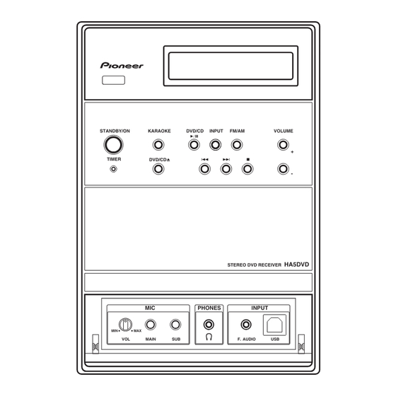
Page 106: Panel Facilities
Selects audio channels for karaoke. 12 PHONES jack STANDBY/ON Headphone jack. Switches the player on or into standby. 13 INPUT TIMER indicator Connect an auxiliary component using a USB Lights when the timer has been set. cable or a stereo mini-jack cable. XV-HA5... - Page 107 KEY - Lights when the Karaoke pitch control is selected. - Lights when the sleep timer is active. ECHO - Lights when the Karaoke ECHO 2 DIGITAL effect is selected. Lights during playback of a Dolby Digital signal. XV-HA5...
-
Page 108: Remote Control
Pauses playback; press again to restart. FUNCTION buttons Selects the source you want to listen to (INPUT cycles through the auxiliary inputs). Stops playback. TIMER/CLOCK ADJ. Use for setting the clock , as well as for setting and checking the timers. XV-HA5... - Page 109 12 KARAOKE controls KARAOKE Selects audio channels for karaoke. ECHO Changes the echo level on the karaoke mics. KEY CONTROL Lowers/raises the pitch of the backing track. 13 DVD/CD Opens/closes the disc tray. XV-HA5...
-
Page 110: Jigs List
Before shipping out the product, be sure to clean the following positions by using the prescribed cleaning tools: Position to be cleaned Cleaning tools Pickup leneses Cleaning liquid : GEM1004 Cleaning paper : GED-008 Position to be cleaned Cleaning tools Fans Cleaning paper : GED-008 XV-HA5...
Need help?
Do you have a question about the XV-HA5 and is the answer not in the manual?
Questions and answers