Table of Contents
Advertisement
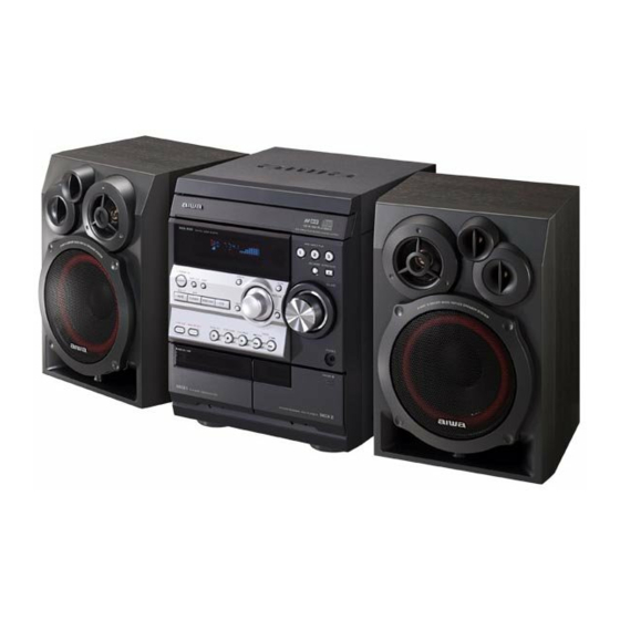
SERVICE MANUAL
CD STEREO SYSTEM
SYSTEM
NSX–R30
NSX–R31
NSX–R37
• This Service Manual is the "Revision Publishing" and replaces "Simple Manual"
NSX-R30/R31/R37<EZ,K>, (S/M Code No. 09-022-454-5T3).
• If requiring information about the CD mechanisim, see Service Manual of BZG-2,
(S/M Code No. 09-023-353-2N8).
NSX-R30
NSX-R31
NSX-R37
BASIC CD MECHANISM : BZG-2 ZD5GNC
BASIC TAPE MECHANISM : ZZM-3 YPR4NC
CD
CASSEIVER
CX–NR30
CX–NR31
CX–NR37
S/M Code No. 09-025-454-5R3
SPEAKER
CONTROLLER
SX–NR30
RC–CAS10
SX–NR37
EZ,K
EZ
EZ
REMOTE
Advertisement
Table of Contents

Related Manuals for Aiwa NSX-R30EZ


Summary of Contents for Aiwa NSX-R30EZ
- Page 1 NSX-R30 EZ,K NSX-R31 NSX-R37 SERVICE MANUAL BASIC CD MECHANISM : BZG-2 ZD5GNC CD STEREO SYSTEM BASIC TAPE MECHANISM : ZZM-3 YPR4NC REMOTE SYSTEM SPEAKER CASSEIVER CONTROLLER NSX–R30 CX–NR30 SX–NR30 RC–CAS10 NSX–R31 CX–NR31 NSX–R37 CX–NR37 SX–NR37 • This Service Manual is the "Revision Publishing" and replaces "Simple Manual" NSX-R30/R31/R37<EZ,K>, (S/M Code No.
-
Page 2: Table Of Contents
TABLE OF CONTENTS SPECIFICATIONS ................................3 PROTECTION OF EYES FROM LASER BEAM DURING SERVICING ................4 NOTE BEFORE STARTING REPAIR ..........................5, 6 ELECTRICAL PARTS LIST (CX-NR30/31/37) ......................7 ~ 19 ELECTRICAL PARTS LIST (ZZM-3 YPR4NC) ......................... 20 TRANSISTOR ILLUSTRATION ............................21 WIRING –... -
Page 3: Specifications
SPECIFICATIONS MAIN UNIT CX-NR30/31/37 GENERAL Power requirements 230 V AC, 50 Hz TUNER Power consumption 75 W FM tuning range 87.5 MHz to 108 MHz Power consumption With ECO mode on: 0.6 W FM usable sensitivity (IHF) 16.8 dBf in standby mode With ECO mode off: 17 W FM antenna terminal 75 ohms (unbalanced) -
Page 4: Protection Of Eyes From Laser Beam During Servicing
PROTECTION OF EYES FROM LASER BEAM DURING SERVICING This set employs laser. Therefore, be sure to follow carefully CAUTION the instructions below when servicing. Use of controls or adjustments or performance of proce- dures other than those specified herin may result in WARNING!! hazardous radiation exposure. -
Page 5: Note On Before Starting Repair
NOTE ON BEFORE STARTING REPAIR 1. Forced discharge of electrolytic capacitor of power supply block When repair is going to be attempted in the set that uses relay circuit in the power supply block, electric potential is kept charged across the electrolytic capacitors (C101, 102) even though AC power cord is removed. - Page 6 In such a case, check also if the POWER AMPLIFIER circuit or power supply circuit has any abnormalities or not. 2-2. Regarding reset There are cases that the machine does not work correctly because the MICROCOMPUTER is not reset even though the AC power cord is re-inserted, or the software reset (pressing the STOP key + POWER key) is performed.
-
Page 7: Electrical Parts List (Cx-Nr30/31/37)
ELECTRICAL PARTS LIST (CX-NR30/31/37) = ! SAFETY PARTS = Components marked All components used on this model at the production line are shown in this service manual. However, please note that not all components will be available as spare parts for after-sales service. Components marked S and O are designated as spare parts for service and will be stocked at the spare parts centers. - Page 8 = ! SAFETY PARTS = Components marked All components used on this model at the production line are shown in this service manual. However, please note that not all components will be available as spare parts for after-sales service. Components marked S and O are designated as spare parts for service and will be stocked at the spare parts centers. Components marked X and R are not designated as spare parts for after sales service, and will not be stocked at the spare parts centers.
- Page 9 = ! SAFETY PARTS = Components marked All components used on this model at the production line are shown in this service manual. However, please note that not all components will be available as spare parts for after-sales service. Components marked S and O are designated as spare parts for service and will be stocked at the spare parts centers. Components marked X and R are not designated as spare parts for after sales service, and will not be stocked at the spare parts centers.
- Page 10 = ! SAFETY PARTS = Components marked All components used on this model at the production line are shown in this service manual. However, please note that not all components will be available as spare parts for after-sales service. Components marked S and O are designated as spare parts for service and will be stocked at the spare parts centers. Components marked X and R are not designated as spare parts for after sales service, and will not be stocked at the spare parts centers.
- Page 11 = ! SAFETY PARTS = Components marked All components used on this model at the production line are shown in this service manual. However, please note that not all components will be available as spare parts for after-sales service. Components marked S and O are designated as spare parts for service and will be stocked at the spare parts centers. Components marked X and R are not designated as spare parts for after sales service, and will not be stocked at the spare parts centers.
- Page 12 = ! SAFETY PARTS = Components marked All components used on this model at the production line are shown in this service manual. However, please note that not all components will be available as spare parts for after-sales service. Components marked S and O are designated as spare parts for service and will be stocked at the spare parts centers. Components marked X and R are not designated as spare parts for after sales service, and will not be stocked at the spare parts centers.
- Page 13 = ! SAFETY PARTS = Components marked All components used on this model at the production line are shown in this service manual. However, please note that not all components will be available as spare parts for after-sales service. Components marked S and O are designated as spare parts for service and will be stocked at the spare parts centers. Components marked X and R are not designated as spare parts for after sales service, and will not be stocked at the spare parts centers.
- Page 14 = ! SAFETY PARTS = Components marked All components used on this model at the production line are shown in this service manual. However, please note that not all components will be available as spare parts for after-sales service. Components marked S and O are designated as spare parts for service and will be stocked at the spare parts centers. Components marked X and R are not designated as spare parts for after sales service, and will not be stocked at the spare parts centers.
- Page 15 = ! SAFETY PARTS = Components marked All components used on this model at the production line are shown in this service manual. However, please note that not all components will be available as spare parts for after-sales service. Components marked S and O are designated as spare parts for service and will be stocked at the spare parts centers. Components marked X and R are not designated as spare parts for after sales service, and will not be stocked at the spare parts centers.
- Page 16 = ! SAFETY PARTS = Components marked All components used on this model at the production line are shown in this service manual. However, please note that not all components will be available as spare parts for after-sales service. Components marked S and O are designated as spare parts for service and will be stocked at the spare parts centers. Components marked X and R are not designated as spare parts for after sales service, and will not be stocked at the spare parts centers.
- Page 17 = ! SAFETY PARTS = Components marked All components used on this model at the production line are shown in this service manual. However, please note that not all components will be available as spare parts for after-sales service. Components marked S and O are designated as spare parts for service and will be stocked at the spare parts centers. Components marked X and R are not designated as spare parts for after sales service, and will not be stocked at the spare parts centers.
- Page 18 = ! SAFETY PARTS = Components marked All components used on this model at the production line are shown in this service manual. However, please note that not all components will be available as spare parts for after-sales service. Components marked S and O are designated as spare parts for service and will be stocked at the spare parts centers. Components marked X and R are not designated as spare parts for after sales service, and will not be stocked at the spare parts centers.
- Page 19 = ! SAFETY PARTS = Components marked All components used on this model at the production line are shown in this service manual. However, please note that not all components will be available as spare parts for after-sales service. Components marked S and O are designated as spare parts for service and will be stocked at the spare parts centers. Components marked X and R are not designated as spare parts for after sales service, and will not be stocked at the spare parts centers.
- Page 20 = ! SAFETY PARTS = Components marked All components used on this model at the production line are shown in this service manual. However, please note that not all components will be available as spare parts for after-sales service. Components marked S and O are designated as spare parts for service and will be stocked at the spare parts centers. Components marked X and R are not designated as spare parts for after sales service, and will not be stocked at the spare parts centers.
-
Page 21: Transistor Illustration
CHIP RESISTOR PART CODE Chip Resistor Part Coding Figure Resistor Code Value of resistor Chip resistor Dimensions (mm) Symbol Wattage Type Tolerance Resistor Code Form 1/16W 1005 0.35 1/16W 1608 0.45 1/10W 2125 1.25 0.45 1/8W 3216 0.55 TRANSISTOR ILLUSTRATION E C B E C B B C E... -
Page 22: Wiring - 1 (Main)
WIRING – 1 (MAIN) – 22 –... -
Page 23: Schematic Diagram - 1 (Main 1/2)
SCHEMATIC DIAGRAM – 1 (MAIN 1 / 2) – 23 –... -
Page 24: Schematic Diagram - 2 (Main 2/2)
SCHEMATIC DIAGRAM – 2 (MAIN 2 / 2) – 24 –... -
Page 25: Wiring - 2 (Front)
WIRING – 2 (FRONT) – 25 –... -
Page 26: Schematic Diagram - 3 (Front / Deck)
SCHEMATIC DIAGRAM – 3 (FRONT / DECK) – 26 –... -
Page 27: Wiring - 3 (Pt)
WIRING – 3 (PT) – 27 –... -
Page 28: Schematic Diagram - 4 (Pt)
SCHEMATIC DIAGRAM – 4 (PT) – 28 –... -
Page 29: Wiring - 4 (Hp)
WIRING – 4 (HP) – 29 –... -
Page 30: Schematic Diagram - 5 (Hp)
SCHEMATIC DIAGRAM – 5 (HP) – 30 –... -
Page 31: Wiring - 5 (Deck)
WIRING – 5 (DECK / HEAD) DECK C.B TO FRONT C.B CN103 (CAM2) (CST2) (REA) (CAM1) (CST1) (FFC103) CRD1 DECK-2 DECK 1 CON351 TO MAIN C.B CN301 – 31 –... -
Page 32: Fl (Cnf-8 Fl-Bj867Gnk) Grid Assignment / Anode Connection
FL (CNF-8 FL-BJ867GNK) GRID ASSIGINMENT / ANODE CONNECTION GRID ASSIGNMENT ANODE CONNECTION – 32 –... -
Page 33: Ic Block Diagram
IC BLOCK DIAGRAM – 33 –... -
Page 34: Ic Description
IC DESCRIPTION PD780226GF-032-3BA<30EZ,30K,37EZ>, PD780228GF-088-3BA<31EZ> µ µ Pin Name Description Pin No. O-MOTOR DECK MOTOR ON/OFF output. O-SOL1 DECK1 solenoid ON/OFF output. O-SOL2 DECK2 solenoid ON/OFF output. O-STBY LED STANDBY LED (Echo mode) output (ON/OFF). O-MUTE System MUTE ON/OFF output. O-KSCAN Switch scan timing output. - Page 35 Pin Name Description Pin No. I-SPEANA_1 A/D input for spectrum analyser level display. I-SPEANA_2 A/D input for spectrum analyser level display. I-SPEANA_3 A/D input for spectrum analyser level display. I-KEY1 Key A/D input 1. I-KEY2 Key A/D input 2. I-TU_SIG Tuner signal input.<31EZ only>...
- Page 37 <TUNER Adjustment> 1. LW VT Adjustment Requirement: • Measuring instrument: Digital multimeter • Test point: TP1 (VT), GND • Adjustment location: L942 1) Connect the digital multimeter between TP1 (VT) and GND. 2) Set the function of the unit to LW, and tune to the receiving frequency at 144kHz. 3) Adjust L942 so that the digital multimeter indicates 1.3±0.05V.
- Page 38 9. MW IF Adjustment Requirement: • Test point: J203 (SP OUT (LCH,RCH)) • Adjustment point: L802 1) Set S.S.G. to AM, carrier of 999kHz with 30% modulation, and source at 1kHz. 2) Tune the receiving frequency of the unit at MW 999kHz. 3) While monitoring the waveform at 1kHz through the oscilloscope, lower the output level of S.S.G.
- Page 39 9. FM Tracking Adjustment Requirement: • Test point: J203 (SP OUT (LCH,RCH)) • Adjustment point: L901,L902,L904,L905 1) Set S.S.G. to FM, carrier of 108MHz with 75kHz modulation, source at 1kHz and output at MAX. 2) Tune the unit to the receiving frequency at FM 108MHz. 3) While monitoring the waveform at 1kHz through the oscilloscope, lower the output level of S.S.G.
-
Page 40: Cd Test Mode
3) Play back the middle part of the test tape (TTA-100), and check that the level is 0.25% or less. 15. Head Azimuth Adjustment (DECK 1 and DECK 2) Requirement • Measuring instrument: Oscilloscope • Test tape: TTA-300(10kHz) • Test point: TP8(LCH),TP9(RCH) •... - Page 41 19. Playback Sensitivity Check (DECK 2) Requirement: • Measuring instrument: AC millivoltmeter, Audio signal generator (low frequency generator), Attenuator • Test tape: TTA-602(NORMAL) • Test point: TP8(LCH),TP9(RCH) • Input point: AUX(1kHz) 1) Insert the test tape (TTA-200) to DECK 2, and record 1kHz signal from AUX. 2) Adjust the attenuator so that the output levels of TP8(LCH) and TP9 (RCH) becomes 100mV.
- Page 42 <FRONT > 1. Clock Adjustment Requirement: • Measuring instrument: Frequency counter • Test point: TP3 (KSCAN), GND • Adjustment point: L951 1) While pressing and holding down the POWER button and UP button, Insert the AC plug to outlet. 2) Adjust L951 so that the frequency counter indicates 84.804±0.084Hz. –...
- Page 43 CD TEST MODE-1/1 1. How to Start the CD Test Mode While pressing the CD OPEN/CLOSE button, insert the AC plug to the power outlet. When the test mode is started, the message [TEST] is displayed. 2. How to Exit the CD Test Mode Press the POWER button, push other FUNCTION button or disconnect the AC plug.
-
Page 44: Mechanical Exploded View
MECHANICAL EXPLODED VIEW – 44 –... -
Page 45: Mechanical Parts List
O MC1029 88-908-301-110 FF-CABLE,8P 1.25 300MM O MC1030 88-911-101-110 FF-CABLE,11P 1.25 100MM O MC1031 8A-NFA-208-010 GUIDE,FL 100-25 ANFA X MC1032 8C-NF8-621-010 PWB,FRONT O MC1033 87-B00-002-010 BADGE,AIWA 30 ABS SIL CX-NR37 CX-NR30 CX-NR30 CX-NR31 EZBC EZSC EZSC O MC1034 8C-NF8-041-010 PANEL,TRAY EZB... -
Page 46: Color Name Table
COLOR NAME TABLE Basic color symbol Color Basic color symbol Color Basic color symbol Color Black Cream Orange Green Gray Blue Transparent Blue Gold Pink Silver Titan Silver Brown Violet White Transparent White Yellow Transparent Yellow Metallic Blue Light Blue Transparent Green Dark Blue Transparent Orange... -
Page 47: Tape Mechanism Exploded View
TAPE MECHANISM EXPLODED VIEW LVR EJECT L LVR EJECT R GEAR PLAY GEAR PLAY – 47 –... -
Page 48: Tape Mechanism Parts List
TAPE MECHANISM PARTS LIST = ! SAFETY PARTS = Components marked All components used on this model at the production line are shown in this service manual. However, please note that not all components will be available as spare parts for after-sales service. Components marked S and O are designated as spare parts for service and will be stocked at the spare parts centers. - Page 49 = ! SAFETY PARTS = Components marked All components used on this model at the production line are shown in this service manual. However, please note that not all components will be available as spare parts for after-sales service. Components marked S and O are designated as spare parts for service and will be stocked at the spare parts centers. Components marked X and R are not designated as spare parts for after sales service, and will not be stocked at the spare parts centers.
-
Page 50: General Speaker Disassembly Instructions (For Reference)
GENERAL SPEAKER DISASSEMBLY INSTRUCTIONS (FOR REFERENCE) Type.1 Type.4 TOOLS Insert a flat-bladed screwdriver into the position indicated by the arrows and remove the panel. Remove the screws of each speaker 1 Plastic head hammer unit and then remove the speaker units. 2 (() flat head screwdriver 3 Cut chisel How to Remove the PANEL, FR... -
Page 51: Speaker Parts List
Components marked X and R are not designated as spare parts for after sales service, and will not be stocked at the spare parts centers. UNIT-NAME ! C REF-NO PARTS-NO PARTS-NAME SUFFIX&MODEL SX-NR30 SX-NR37 OTHERS 88-NSK-610-010 SPKR, CERAMIC ASSY OTHERS 8A-NSJ-006-010 BADGE,AIWA S35 OTHERS 8B-NSH-612-010 CORD,SPKR OTHERS 8B-NSK-604-010 SPKR, T 60 OTHERS 8C-NS6-003-010 PROTECTOR, W OTHERS 8C-NS7-604-010 SPKR, W 160 25/4 OTHERS... - Page 52 ACCESSORIES PARTS LIST = ! SAFETY PARTS = Components marked All components used on this model at the production line are shown in this service manual. However, please note that not all components will be available as spare parts for after-sales service. Components marked S and O are designated as spare parts for service and will be stocked at the spare parts centers.
-
Page 53: Other Parts List (Cx-Nr30/31/37)
OTHER PARTS LIST (CX-NR30/31/37) = ! SAFETY PARTS = Components marked All components used on this model at the production line are shown in this service manual. However, please note that not all components will be available as spare parts for after-sales service. Components marked S and O are designated as spare parts for service and will be stocked at the spare parts centers. -
Page 54: Other Parts List (Sx-Nr30/37)
OTHER PARTS LIST (SX-NR30/37) = ! SAFETY PARTS = Components marked All components used on this model at the production line are shown in this service manual. However, please note that not all components will be available as spare parts for after-sales service. Components marked S and O are designated as spare parts for service and will be stocked at the spare parts centers. - Page 55 2-11, IKENOHATA 1-CHOME, TAITO-KU, TOKYO 110-8710, JAPAN TEL:03 (3827) 3111 9620450 0251431...
Need help?
Do you have a question about the NSX-R30EZ and is the answer not in the manual?
Questions and answers