Table of Contents
Advertisement
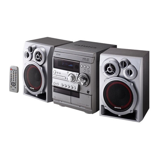
SERVICE MANUAL
CD STEREO SYSTEM
SYSTEM
NSX-R41
If requiring information about the CD mechanism, see Service Manual of
BZG-2, (S/M Code No. 09-023-353-2N8),
NSX-R41
BASIC CD MECHANISM : BZG-2 ZD5GNC
BASIC TAPE MECHANISM : ZZM-3 YPR4NC
CD
CASSEIVER
CX-NR41
S/M Code No. 09-027-453-4N3
SPEAKER
CONTROLLER
SX-NR40
RC-CAS10
EZ(S)
REMOTE
Advertisement
Table of Contents

Related Manuals for Aiwa NSX-R41


Summary of Contents for Aiwa NSX-R41
- Page 1 NSX-R41 EZ(S) SERVICE MANUAL BASIC CD MECHANISM : BZG-2 ZD5GNC CD STEREO SYSTEM BASIC TAPE MECHANISM : ZZM-3 YPR4NC REMOTE SYSTEM SPEAKER CASSEIVER CONTROLLER NSX-R41 CX-NR41 SX-NR40 RC-CAS10 If requiring information about the CD mechanism, see Service Manual of BZG-2, (S/M Code No. 09-023-353-2N8),...
-
Page 2: Table Of Contents
TABLE OF CONTENTS -1/1 SPECIFICATIONS ................................3 PROTECTION OF EYES FROM LASER BEAM DURING SERVICING ..............4 NOTE ON BEFORE STARTING REPAIR ........................5, 6 ACCESSORIES PARTS LIST .............................. 7 ELECTRICAL PARTS LIST ............................8 ~ 22 TRANSISTOR ILLUSTRATION ............................23 SCHEMATIC DIAGRAM -1/5 (MAIN-1/2, AMP SECTION) .................... -
Page 3: Specifications
SPECIFICATIONS -1/1 MAIN UNIT CX-NR41 CD PLAYER TUNER Laser Semiconductor laser (λ= 780 nm) FM tuning range 87.5 MHz to 108 MHz D/A converter 1 bit dual FM usable sensitivity (IHF) 16.8 dBf Signal-to-noise ratio 85 dB (1 kHz, 0 dB) FM antenna terminal 75 ohms (unbalanced) Harmonic distortion... -
Page 4: Protection Of Eyes From Laser Beam During Servicing
PROTECTION OF EYES FROM LASER BEAM DURING SERVICING -1/1 CAUTION This set employs laser. Therefore, be sure to follow carefully the instructions below when servicing. Use of controls or adjustments or performance of proce- dures other than those specified herin may result in WARNING!! hazardous radiation exposure. -
Page 5: Note On Before Starting Repair
NOTE ON BEFORE STARTING REPAIR -1/2 1. Forced discharge of electrolytic capacitor of power supply block When repair is going to be attempted in the set that uses relay circuit in the power supply block, electric potential is kept charged across the electrolytic capacitors (C101, 102) even though AC power cord is removed. -
Page 6: Note On Before Starting Repair
NOTE ON BEFORE STARTING REPAIR -2/2 In such a case, check also if the POWER AMPLIFIER circuit or power supply circuit has any abnormalities or not. 2-2. Regarding reset There are cases that the machine does not work correctly because the MICROCOMPUTER is not reset even though the AC power cord is re-inserted, or the software reset (pressing the STOP key + POWER key) is performed. -
Page 7: Accessories Parts List
Components marked X and R are not designated as spare parts for after sales service, and will not be stocked at the spare parts centers. UNIT-NAME ! C REF-NO PARTS-NO PARTS-NAME SUFFIX&MODEL CX-SNR41 EZSC O AS1001 8C-NF7-906-010 IB,EZ(9L)FM NSX-R41 X AS1002 8C-NF8-703-010 RC UNIT,RC-CAS10(SMK) O AS1003 87-A92-150-010 ANT,LOOP AM NO-CONT X AS1004 87-A92-346-010 ANT,WIRE FM(FASTEN) -
Page 8: Electrical Parts List - 1/15
ELECTRICAL PARTS LIST - 1/15 = ! SAFTY PARTS = Components marked All components used on this model at the production line are shown in this service manual. However, please note that not all components will be available as spare parts for after-sales service. Components marked S and O are designated as spare parts for service and will be stocked at the spare parts centers. - Page 9 ELECTRICAL PARTS LIST - 2/15 = ! SAFTY PARTS = Components marked All components used on this model at the production line are shown in this service manual. However, please note that not all components will be available as spare parts for after-sales service. Components marked S and O are designated as spare parts for service and will be stocked at the spare parts centers.
- Page 10 ELECTRICAL PARTS LIST - 3/15 = ! SAFTY PARTS = Components marked All components used on this model at the production line are shown in this service manual. However, please note that not all components will be available as spare parts for after-sales service. Components marked S and O are designated as spare parts for service and will be stocked at the spare parts centers.
- Page 11 ELECTRICAL PARTS LIST - 4/15 = ! SAFTY PARTS = Components marked All components used on this model at the production line are shown in this service manual. However, please note that not all components will be available as spare parts for after-sales service. Components marked S and O are designated as spare parts for service and will be stocked at the spare parts centers.
- Page 12 ELECTRICAL PARTS LIST - 5/15 = ! SAFTY PARTS = Components marked All components used on this model at the production line are shown in this service manual. However, please note that not all components will be available as spare parts for after-sales service. Components marked S and O are designated as spare parts for service and will be stocked at the spare parts centers.
- Page 13 ELECTRICAL PARTS LIST - 6/15 = ! SAFTY PARTS = Components marked All components used on this model at the production line are shown in this service manual. However, please note that not all components will be available as spare parts for after-sales service. Components marked S and O are designated as spare parts for service and will be stocked at the spare parts centers.
- Page 14 ELECTRICAL PARTS LIST - 7/15 = ! SAFTY PARTS = Components marked All components used on this model at the production line are shown in this service manual. However, please note that not all components will be available as spare parts for after-sales service. Components marked S and O are designated as spare parts for service and will be stocked at the spare parts centers.
- Page 15 ELECTRICAL PARTS LIST - 8/15 = ! SAFTY PARTS = Components marked All components used on this model at the production line are shown in this service manual. However, please note that not all components will be available as spare parts for after-sales service. Components marked S and O are designated as spare parts for service and will be stocked at the spare parts centers.
- Page 16 ELECTRICAL PARTS LIST - 9/15 = ! SAFTY PARTS = Components marked All components used on this model at the production line are shown in this service manual. However, please note that not all components will be available as spare parts for after-sales service. Components marked S and O are designated as spare parts for service and will be stocked at the spare parts centers.
- Page 17 ELECTRICAL PARTS LIST - 10/15 = ! SAFTY PARTS = Components marked All components used on this model at the production line are shown in this service manual. However, please note that not all components will be available as spare parts for after-sales service. Components marked S and O are designated as spare parts for service and will be stocked at the spare parts centers.
- Page 18 ELECTRICAL PARTS LIST - 11/15 = ! SAFTY PARTS = Components marked All components used on this model at the production line are shown in this service manual. However, please note that not all components will be available as spare parts for after-sales service. Components marked S and O are designated as spare parts for service and will be stocked at the spare parts centers.
- Page 19 ELECTRICAL PARTS LIST - 12/15 = ! SAFTY PARTS = Components marked All components used on this model at the production line are shown in this service manual. However, please note that not all components will be available as spare parts for after-sales service. Components marked S and O are designated as spare parts for service and will be stocked at the spare parts centers.
- Page 20 ELECTRICAL PARTS LIST - 13/15 = ! SAFTY PARTS = Components marked All components used on this model at the production line are shown in this service manual. However, please note that not all components will be available as spare parts for after-sales service. Components marked S and O are designated as spare parts for service and will be stocked at the spare parts centers.
- Page 21 ELECTRICAL PARTS LIST - 14/15 = ! SAFTY PARTS = Components marked All components used on this model at the production line are shown in this service manual. However, please note that not all components will be available as spare parts for after-sales service. Components marked S and O are designated as spare parts for service and will be stocked at the spare parts centers.
-
Page 22: Electrical Parts List
ELECTRICAL PARTS LIST - 15/15 • Regarding connectors, they are not stocked as they are not the initial order items. The connectors are available after they are supplied from connector manufacturers upon the order is received. CHIP RESISTOR PART CODE Chip Resistor Part Coding Figure Resistor Code... -
Page 23: Transistor Illustration
TRANSISTOR ILLUSTRATION -1/1 E C B E C B B C E E C B 2SC3331(T/U) 2SB1548 2SA1980G 2SA1585SR 2SC3478LK 2SB1686 2SC5343G 2SC5343GL 2SD2642 S D G G D S E C B 2SK2541 2SK2937 SRA2202S 2SC3906KR 2SA1981Y SRA2207S 2SC5345SF/S(O) 2SJ460 2SA1235F 2SD814A(RS) -
Page 24: Schematic Diagram -1/5 (Main-1/2, Amp Section)
SCHEMATIC DIAGRAM - 1/5 (MAIN -1/2, AMP SECTION) MAIN C.B 1/2 (AMP SECTION) TO MAIN C.B (TUNER SECTION) 1A-16A 1/50 1/50 220/10 47/25 Q113,127 2SC3052F 1/50 0.33/50 D109 L CH 33/50 1SS244 R CH Q111 2SC3478 Q114,128 2SC3052F R166 1/50 0.33/50 1.5K D110... -
Page 25: Schematic Diagram -2/5 (Main-2/2, Tuner Section)
SCHEMATIC DIAGRAM - 2/5 (MAIN -2/2, TUNER SECTION) Q902 L901,902,904,905 Q901 MAIN C.B 2/2 (TUNER SECTION) C916 Q903-905 Q835 L801 L802 2SC5345SF/S(O) AM IF ADJ. FM IF AMP FM BAND SW 7.76V 12.06V C798 5.55V MS2GH-A ANTENNA FM75 (COAXIAL) 11.32V MW/LW C802 LOOP... -
Page 26: Schematic Diagram -3/5 (Hp Section)
SCHEMATIC DIAGRAM -3/5 (HP SECTION) HP C.B -26-... -
Page 27: Wiring -1/4 (Main C.b, Hp C.b)
WIRING - 1/4 (MAIN C.B/HP C.B) CNA302 CNA301 L941 R969 C870 Q948 R871 C952 IC861 R870 TC942 1 2 3 L942 R610 Q951 C877 R952 C879 Q861 C948 C876 C878 6 5 4 R958 J832 X862 R948 R867 ANTENNA R864 R863 Q952 J832... -
Page 28: Schematic Diagram -4/5 (Front/Deck Section)
SCHEMATIC DIAGRAM - 4/5 (FRONT/DECK SECTION) -28-... -
Page 29: Wiring -2/4 (Front C.b/Mic C.b)
WIRING - 2/4 (FRONT C.B) R701 R702 R703 S350 S350 S351 R351 S351 R349 R350 -29-... -
Page 30: Wiring -3/4 (Deck C.b)
WIRING - 3/4 (DECK C.B) TO FRONT C.B CN104 DECK C . B FFC104 CRD1 CNA302 CNA301 TO MAIN C.B CN302 TO MAIN C.B CN301 -30-... -
Page 31: Schematic Diagram -5/5 (Pt Section)
SCHEMATIC DIAGRAM -5/5 (PT SECTION) PT C.B CNF-7 EZ RELAY,AC12V PT,SUB EZ YKP01246B AC230V, 50Hz BLK CC -31-... -
Page 32: Wiring -4/4 (Pt C.b)
WIRING - 4/4 (PT C.B) TO MAIN C.B WH001 PT C.B AC230V, 50Hz T002 WH002 D091 PT002 D092 RY001 T001 PR003 PT001 C091 -32-... -
Page 33: Electrical Adjustment
ELECTRICAL ADJUSTMENT -1/7 MAIN C.B PARTS SIDE TC942 L941 L942 L953 L952 L901 SFR451 L907 SFR452 L905 L904 L902 MAIN C.B PATTERN SIDE IC801 DECK C.B MOTOR -33-... - Page 34 ELECTRICAL ADJUSTMENT -2/7 <TUNER Adjustment> 1. VT Check (MW) Requirements • Measuring instrument: Digital multimeter Test points: VT, GND 1) Connect the digital multimeter between VT and GND. 2) Set the function to MW, and tune the receiving frequency of the unit at 1,602 kHz. 3) Check that the digital multimeter ranges under 8 V.
- Page 35 ELECTRICAL ADJUSTMENT -3/7 <MW/LW Adjustment> Make the following preparations for MW/LW adjustment. Preparations ´ • Standard Signal Generator (S.S.G.) / Loop antenna / Oscilloscope / Millivoltmeter / Dummy resistance (6y) 1) Connect the unit and measuring instruments as shown in the diagram below. 2) Position the loop antenna connected to S.S.G.
- Page 36 ELECTRICAL ADJUSTMENT -4/7 <FM Adjustment> Make the following preparations for FM adjustment. Preparations ´ • Standard Signal Generator (S.S.G.) / Loop antenna / Oscilloscope / Millivoltmeter / Dummy resistance (6y) 1) Connect the unit and measuring instruments as shown in the diagram below. 2) Connect the output of S.S.G.
- Page 37 ELECTRICAL ADJUSTMENT -5/7 <DECK Section> 12. Tape Speed Adjustment (DECK 2) Requirements • Measuring instrument: Wow and flutter meter (frequency counter) Test tape: TTA-100 (3 kHz) Test point: HP OUT Adjustment point: DECK MOTOR SFR 1) Connect the wow and flutter meter to HP OUT of the unit. 2) Insert the test tape (TTA-100) to DECK 2.
- Page 38 ELECTRICAL ADJUSTMENT -6/7 17. Playback Sensitivity Check (DECK 1 and DECK 2) Requirements • Measuring instrument: Millivoltmeter Test tape: TTA-200 (400 kHz) Test points: TP8 (Lch), TP9 (Rch) 1) Connect CH1 of the millivoltmeter to TP8 (Lch) and CH2 to TP9 (Rch). 2) Insert the test tape (TTA-200) to DECK 1 and play back.
- Page 39 ELECTRICAL ADJUSTMENT -7/7 <FRONT Section> FRONT C.B PATTERN SIDE CLOCK FRONT C.B PARTS SIDE L951 20. Clock Adjustment Requirements • Measuring instrument: Frequency counter Test point: CLOCK, GND Adjustment point: L951 1) While pressing the UP and POWER button, insert the AC plug to the outlet. 2) Adjust L951 so that the frequency counter indicates the frequency level within 72.743 ±...
-
Page 40: Cd Test Mode
CD TEST MODE -1/1 CD TEST MODE Ver. 3.0 1. Starting CD Test Mode While pressing and holding down the CD OPEN/CLOSE button, insert the AC plug to outlet. When test mode starts, the message, TEST appears on the display. 2. -
Page 41: Fl Display (Bj854Gnk Bnf-1)
FL DISPLAY - 1/2 (BJ854GNK BNF-1) GRID ASSIGNMENT PIN CONNECTION -41-... - Page 42 FL DISPLAY - 2/2 (BJ854GNK BNF-1) ANODE CONNECTION -42-...
-
Page 43: Ic Block Diagram
IC BLOCK DIAGRAM -1/2 IC, BD3881FV IC, BU1920FS -43-... -
Page 44: Ic Block Diagram
IC BLOCK DIAGRAM -2/2 IC, LA1845N-A IC, LC7213D-N -44-... -
Page 45: Ic Description
IC DESCRIPTION -1/1(µPD780228GF-087-3BA)-1/2 Pin Name Pin No. Description O-MOTOR DECK motor output. O-SOL1 DECK1 solenoid output. O-SOL2 DECK2 solenoid output. O-STBY LED Standby LED output. O-MUTE System mute ON/OFF output. O-KSCAN Key scan timing output. O-PLL_CE PLL chip enable output for LC72131D-N. I-TM_BASE Time-base signal input. -
Page 46: Ic Description
IC DESCRIPTION -1/1(µPD780228GF-087-3BA)-2/2 Pin Name Description Pin No. I-SPEANA_1 A/D input for spectrum analyser level display. I-SPEANA_2 A/D input for spectrum analyser level display. I-SPEANA_3 A/D input for spectrum analyser level display. I-KEY 1 Key A/D input 1. I-KEY 2 Key A/D input 2. -
Page 47: Mechanical Exploded View
MECHANICAL EXPLODED VIEW -1/1 -47-... -
Page 48: Mechanical Parts List
88-908-301-110 FF-CABLE,8P 1.25 300MM O MC1030 88-911-101-110 FF-CABLE,11P 1.25 100MM O MC1031 8B-NF9-207-010 GUIDE,FL 90.2-20 X MC1032 8C-NF7-641-010 PWB,FRONT O MC1033 87-B00-002-010 BADGE,AIWA 30 ABS SIL X MC1034 8C-NF8-008-010 PANEL,TRAY X MC1035 M8-BZG-29G-170 BZG-2 ZD5GNC O MC1036 8A-NF8-206-010 HLDR,PWB M O MC1037... -
Page 49: Color Name Table
COLOR NAME TABLE -1/1 Basic color symbol Color Basic color symbol Color Basic color symbol Color Black Cream Orange Green Gray Blue Transparent Blue Gold Pink Silver Titan Silver Brown Violet White Transparent White Yellow Transparent Yellow Metallic Blue Light Blue Transparent Green Dark Blue Transparent Orange... -
Page 50: Tape Mechanism Exploded View
TAPE MECHANISM EXPLODED VIEW <ZZM-3 YPR4NC> -1/1 IC, EW732 IC, EW732 -50-... -
Page 51: Tape Mechanism Parts List
TAPE MECHANISM PARTS LIST <ZZM-3 YPR4NC> -1/2 = ! SAFTY PARTS = Components marked All components used on this model at the production line are shown in this service manual. However, please note that not all components will be available as spare parts for after-sales service. Components marked S and O are designated as spare parts for service and will be stocked at the spare parts centers. -
Page 52: Tape Mechanism Parts List
TAPE MECHANISM PARTS LIST <ZZM-3 YPR4NC> -2/2 = ! SAFTY PARTS = Components marked All components used on this model at the production line are shown in this service manual. However, please note that not all components will be available as spare parts for after-sales service. Components marked S and O are designated as spare parts for service and will be stocked at the spare parts centers. -
Page 53: General Speaker Disassembly Instructions (For Reference)
GENERAL SPEAKER DISASSEMBLY INSTRUCTIONS (FOR REFERENCE) -1/1 Type.1 Type.4 Insert a flat-bladed screwdriver into the position indicated by the TOOLS arrows and remove the panel. Remove the screws of each speaker Plastic head hammer unit and then remove the speaker units. ) flat head screwdriver Cut chisel How to Remove the PANEL, FR... -
Page 54: Speaker Parts List (Sx-Nr40)
Components marked X and R are not designated as spare parts for after sales service, and will not be stocked at the spare parts centers. UNIT-NAME ! C REF-NO PARTS-NO PARTS-NAME SUFFIX&MODEL SX-SNR40 O SP1001 88-NSK-610-010 SPKR, CERAMIC ASSY O SP1002 8A-NSJ-006-010 BADGE,AIWA S35 O SP1003 8B-NSH-612-010 CORD,SPKR O SP1004 8B-NSK-604-010 SPKR, T 60 X SP1005 8C-NS6-003-010 PROTECTOR, W X SP1006 8C-NS7-003-010 LBL,SPEC YS... -
Page 55: Other Parts List
OTHER PARTS LIST -1/2 = ! SAFTY PARTS = Components marked All components used on this model at the production line are shown in this service manual. However, please note that not all components will be available as spare parts for after-sales service. Components marked S and O are designated as spare parts for service and will be stocked at the spare parts centers. -
Page 56: Other Parts List
OTHER PARTS LIST -2/2 <TAPE MECHANISM ZZM-3 YPR4NC> = ! SAFTY PARTS = Components marked All components used on this model at the production line are shown in this service manual. However, please note that not all components will be available as spare parts for after-sales service. Components marked S and O are designated as spare parts for service and will be stocked at the spare parts centers. - Page 57 2-11, IKENOHATA 1-CHOME, TAITO-KU, TOKYO 110-8710, JAPAN TEL:03 (3827) 3111 0251431...
Need help?
Do you have a question about the NSX-R41 and is the answer not in the manual?
Questions and answers