Table of Contents
Advertisement
SERVICE MANUAL
Ver 1.1 2002.10
DECK A (the CD player section)
System
Compact disc and digital audio system
Laser
Semiconductor laser (λ =780 nm)
Emission duration: continuous
Frequency response
20 Hz – 20,000 Hz (±0.5 dB)
Signal-to-noise ratio
More than 100 dB
Dynamic range
More than 95 dB
DECK B (the CD-R and CD-RW recording section)
System
Compact disc digital audio system
Laser
Semiconductor laser (λ =780 nm)
Emission duration: continuous
Playable discs
CD, CD-R, CD-RW
Recordable discs
CD-R, CD-RW (for music use)
Frequency response
20 to 20,000 Hz ±0.5 dB
Signal-to-noise ratio
Over 100 dB during playback
Dynamic range
More than 95 dB during playback
Inputs
ANALOG IN
(Phono jacks)
impedance 47 kilohms
Rated input 330 mVrms
Minimum input 125 mVrms
DIGITAL OPTICAL IN
(Square optical connector jack) Optical wavelength 660 nm
Sony Corporation
9-874-117-02
Home Audio Company
2002J0200-1
Pubulished by Sony Engineering Corporation
© 2002.10
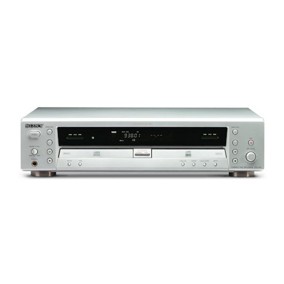
RCD-W3
Model Name Using Similar Machanism RCD-W1
CD-R
CD Mechanism Type
Optical Pick-up Type
Model Name Using Similar Mechanism RCD-W1
CDP
CD Mechanism Type
SPECIFICATIONS
Outputs
ANALOG OUT
(Phono jacks)
OPTICAL DIGITAL OUT
(Square optical connector jack) Wavelength 660 nm
PHONES
(Phone jacks)
General
Power requirements
U.S.A. and Canada
Other countries
Power consumption
Dimensions (approx.) (w/h/d) incl. projecting parts and control
Mass (approx.)
Supplied accessories
Design and specifications are subject to change without notice.
COMPACT DISC RECORDER
US Model
Canadian Model
AEP Model
UK Model
CDM-700(CD-RW)
KRS-220C
CDM-700(CDP)
Rated output 2 Vrms (at 50 kilohms)
Load impedance over 10 kilohms
Output level -18 dBm
28 mW, 32 ohms
120 V AC, 60 Hz
110 – 240 V AC, 50/60 Hz
20 W
430 x 108 x 368 mm
4.6 kg
• Audio connecting cord (2)
• Remote commander (remote) (1)
• Size AA (R6) batteries (2).
Advertisement
Table of Contents

Related Manuals for Sony RCD-W3


Summary of Contents for Sony RCD-W3
- Page 1 • Size AA (R6) batteries (2). DIGITAL OPTICAL IN (Square optical connector jack) Optical wavelength 660 nm Design and specifications are subject to change without notice. COMPACT DISC RECORDER Sony Corporation 9-874-117-02 Home Audio Company 2002J0200-1 Pubulished by Sony Engineering Corporation © 2002.10...
- Page 2 REPLACE THESE COMPONENTS WITH SONY PARTS FONCTIONNEMENT. NE REMPLACER CES COMPOSANTS WHOSE PART NUMBERS APPEAR AS SHOWN IN THIS QUE PAR DES PIÈCES SONY DONT LES NUMÉROS MANUAL OR IN SUPPLEMENTS PUBLISHED BY SONY. SONT DONNÉS DANS CE MANUEL OU DANS LES...
-
Page 3: Table Of Contents
RCD-W3 TABLE OF CONTENTS Error Messages 1. SERVICING NOTE ............4 The following table explains the error messages that appear in the 2. GENERAL ................8 display. 3. DISASSEMBLY Message Explanation 3-1. Top Case ................9 CHECK DISC • A record-related button has been 3-2. -
Page 4: Servicing Note
RCD-W3 SECTION 1 SERVICING NOTE NOTES REGARDING HANDLING OF THE PICK-UP 1. Notes for transport and storage 1) The pick-up should always be left in its conductive bag until immediately prior to use. 2) The pick-up should never be subjected to external pressure or impact. - Page 5 RCD-W3 NOTES REGARDING COMPACT DISC PLAYER REPAIRS 1. Preparations 1) Compact disc players incorporate a great many ICs as well as the pick-up (laser diode). These compo- nents are sensitive to, and easily affected by, static electricity. If such static is high voltage, components can be damaged, and for that reason components should be handled with care.
- Page 6 RCD-W3 Electrostatically Sensitive Devices (ESD) Some semiconductor (solid state) devices can be damaged easily by static electricity. Such components com- monly are called Electrostatically Sensitive Devices (ESD). Examples of typical ESD devices are integrated cir- cuits and some field-effect transistors and semiconductor chip components. The following techniques should be used to help reduce the incidence of component damage caused by static electricity.
- Page 7 RCD-W3 NOTE ON CHECKING POWER SUPPLY CIRCUIT 4. When check the primary part, after remove power cord and dis 1. When check the primary part, you must remove the GND pin of charge the primary capacitor, and then check the system.
-
Page 8: General
RCD-W3 SECTION 2 GENERAL This section is extracted from instruction manual. Parts and Controls 1 2 3 90 qa qd qs (stop) button -Deck B 1 POWER button qg INPUT button 2 H (play) button -Deck A qh LEVEL SYNC button... -
Page 9: Disassembly
RCD-W3 SECTION 3 DISASSEMBLY Note: Disassemble the unit in the order as shown below. Top case Tray door, Front panel assy Back panel HP board, FL board, VOL board Audio board Power board CDP deck assy (deck A) BD-P board (deck A) -
Page 10: Tray Door, Front Panel Assy
RCD-W3 3-2. TRAY DOOR, FRONT PANEL ASSY 1 Insert a screwdriver to the square hole on the bottom, and slide the white lever in the arrow A direction to open the tray. Then remove the tray door. (In the case of DECK B, remove it in the same manner.) -
Page 11: Back Panel
RCD-W3 3-4. BACK PANEL 3 Cord power 5 Back panel 1 Four screws (3X10) Two screws (3X8 BK) 3-5. AUDIO BOARD 2 Connector (PN201) 3 Two screws (special) Wire (flat type) (PN501) 4 Three screws (special) 6 AUDIO board... -
Page 12: Power Board
RCD-W3 3-6. POWER BOARD 2 Two screws (special) Two screws (special) 1 Connector (PN503) 5 POWER board 3-7. CDP DECK ASSY (DECK A), CD-R DECK ASSY (DECK B) 2 Two screws (special) 3 Two screws (special) 6 CDP deck assy (deck A) -
Page 13: Bd-P Board (Deck A)
RCD-W3 3-8. BD-P BOARD (DECK A) 3 Claw 1 Wire (flat type) (PN4M3) 1 Wire (flat type) (PN4M4) Connector (PN4M5) BD-P board 2 Two screws (2X6) 3-9. CDP MECHANISM ASSY (DECK A) 3 Clamp holder assy 1 Screw (1.7X6) Two screws (2.0X10) 4 Push out the disc tray by pushing the Up/Down guide un the drrow A direction. -
Page 14: 3-10.Spindle Motor Assy, Optical Pick-Up Block (Deck A)
RCD-W3 3-10. SPINDLE MOTOR ASSY, OPTICAL PICK-UP BLOCK (DECK A) 5 Screw (1.7X5) 3 Screw (1.7X5) 8 Optical pick-up block 4 Shaft L 6 Shaft R Spindle motor assy 1 Three screws (2X6) 3-11. BD-R BOARD (DECK B) 1 Three claws... -
Page 15: 3-12.Cd-R Mechanism Assy (Deck B)
RCD-W3 3-12. CD-R MECHANISM ASSY (DECK B) 3 Clamp holder assy 1 Screw (2X6) Two screws (2.0X10) 4 Push out the disc tray by pushing the 9 CD-R mechanism assy Up/Down suide un the drrow A direction. Up/Down guide Main base... -
Page 16: Electrical Adjustment
Start up Procedure: 1. Connect the PC connection jig with the RS-232C cable between the test connector (PN105) on CD-R of RCD-W3 and COM port on PC.(Check SW501 on the PC connection jig to “D” side.) 2. Turn power on RCD-W3. - Page 17 RCD-W3 CD-R LD Setting Check (VRDC/VWDC/FPD Level Value Check) This routine is for checking performances of the record/playback D-A converter (IC304), the encoder/decoder IC (IC301), CPLD (IC207), the optical pick-up block (KRS-220C), the microcomputer(IC203) and so on. It diagnoses malfunctions of interface, the pick-up or so on.
- Page 18 RCD-W3 Description of each parameter VRDC: Used on the Read Power setting in case of reading CD-RW and CD-R. (DAC value on 100mW.) VWDC: There is VWDC1 (Write power) pin in the optical pick-up block. The recording power is set by it and VWDC2 (Over drive) pin.
- Page 19 RCD-W3 Procedure : SERVO Check 1. Connect oscilloscope to IC402 wg pin (TE) and IC402 wk pin (VC). CD SECTION 2. Turned Power switch on. Note : 3. Load a disc (YEDS-18) and playback the number five track. 1. CD Block is basically designed to operate without adjustment.
- Page 20 RCD-W3 CD-R SECTION Adjustment Location: Note : 1. CD Block is basically designed to operate without adjustment. [BD-R BOARD] (SIDE A) Therefore, check each item in order given. 2. Use YEDS-18 disc (3-702-101-01) unless otherwise indicated. 3. Use an oscilloscope with more than 10M impedance.
-
Page 21: Diagrams
RCD-W3 SECTION 5 DIAGRAMS THIS NOTE IS COMMON FOR PRINTED WIRING BOARDS AND SCHEMATIC DIAGRAMS. (In addition to this, the necessary note is printed in each block.) • Signal path. : CD c : CD (digital) For schematic diagrams. I : CD REC... - Page 22 RCD-W3 – BD-R SECTION – IC301 ia (RRF IN) IC403 qg (RF AC) IC502 qs (ILRCK) IC408 2 (XOUT) 3.2 Vp-p 4.9 Vp-p 0.8 Vp-p 1.6 Vp-p 33.86MHz 1V/div 21 µ sec 1V/div 0.2V/div 0.5V/div 10 µ sec/div 20nsec/div 0.5 µ sec/div 0.5 µ...
-
Page 23: Block Diagrams - Cd-R Section (1/2)
RCD-W3 5-2. BLOCK DIAGRAMS – CD-R SECTION (1/2) – RF EQUALIZER, OPTICAL FOCUS/TRACKING,ERROR PICK-UP BLOCK DETECT (KRS-220C) IC301 (DECK B) EFM(RFAC) EQRFP EQRFN SRFO RF EQ MATRIX BH01 BH01 PH/BH TEIN CD-R IC306 (1/2) RREF2 SECTION (2/2) TE AMP VWDCN... -
Page 24: Block Diagrams - Cd-R Section (2/2)
RCD-W3 – CD-R SECTION (2/2) – IC706(2/2) IC706(1/2) JK703 JK705 F DOUT DIGITAL DIGITAL WAVE WAVE OPTICAL OPTICAL R OPT IN DOUT SHAPER SHAPER RW DOUT AES3 DOUT RW DOUT SRC RXP CLOCK&DATA 163 EFM RECEIVER S/PDIF RECOVERY ROUT RW DATA... -
Page 25: Block Diagrams - Cdp Section
RCD-W3 – CDP SECTION – DIGITAL SERVO DIGITAL SIGNAL PROCESSOR IC402 RF AMP OPTICAL IC403 PICK-UP BLOCK (DECK A) EQ_IN P DOUT RFAC RFAC DIGITAL DOUT REGISTER DEMODULATOR PROCESSOR PCMD48 P DATA DATA BUS ERROR SERIAL/ BCK48 RFDCO P BCK... -
Page 26: Block Diagrams - Audio Section
RCD-W3 – AUDIO SECTION – D/A CONVERTER L-P-F IC7V1 IC704 JK701 (1/2) AOUTL+ SDT1 DA DATA AOUTL- BICK DA CLK ANALOG LRCK DA LRCK AOUTR+ MCLK DA MCLK AOUTR- SDT DAC SCK DAC CS DAC DAC RST PHONES AMP IC707... -
Page 27: Block Diagrams - Power Section
RCD-W3 – POWER SECTION – KEY IN0 KEY MATRIX SW801 - 807 KEY IN1 SW808, 5W810 - 814 SW815 - 822 RMC801 KEY IN2 REMOTE COMMANDER RMC IN RECIEVER FLD TXD PT101 G1 - 16 POWER FLD CLK SCK1 TRANSFORMER... -
Page 28: Printed Wiring Board - Bd-R Section (Side A)
RCD-W3 5-3.PRINTED WIRING BOARD BD-R SECTION • See page 21 for Circuit Board location. – – BD–R BOARD (SIDE A) C541 C534 • Semiconductor C523 IC410 Location Ref. No. Location R506 D402 R525 IC502 IC202 R522 R521 R520 IC203 R519... -
Page 29: Printed Wiring Board - Bd-R Section (Side B)
RCD-W3 OPTICAL PICK-UP BLOCK (KRS–220C) AUDIO POWER (DECK B) BOARD BOARD (Page36) • Semiconductor BD–R BOARD (SIDE B) (Page40) Location Ref. No. Location C533 C457 D301 C463 PN501 C524 L501 L441 PN503 IC201 C530 C532 IC207 100 95 90 85 80 76... -
Page 30: Schematic Diagram - Bd-R Section (1/6)
RCD-W3 5-4.SCHEMATIC DIAGRAM BD-R SECTION (1/6) – –... -
Page 31: Schematic Diagram - Bd-R Section (2/6)
RCD-W3 5-5.SCHEMATIC DIAGRAM BD-R SECTION (2/6) – –... -
Page 32: Schematic Diagram - Bd-R Section (3/6)
RCD-W3 5-6.SCHEMATIC DIAGRAM BD-R SECTION (3/6) • See page 43, 45 for IC Pin Function Description. – –... -
Page 33: Schematic Diagram - Bd-R Section (4/6)
RCD-W3 5-7.SCHEMATIC DIAGRAM – BD-R SECTION (4/6) –... -
Page 34: Schematic Diagram - Bd-R Section (5/6)
RCD-W3 5-8.SCHEMATIC DIAGRAM BD-R SECTION (5/6) – –... -
Page 35: Schematic Diagram - Bd-R Section (6/6)
RCD-W3 5-9.SCHEMATIC DIAGRAM BD-R SECTION (6/6) • See page 46 for IC Pin Function Description. – –... -
Page 36: Printed Wiring Board - Audio Section
RCD-W3 5-10.PRINTED WIRING BOARD AUDIO SECTION • See page 21 for Circuit Board location. – – POWER BOARD • Semiconductor AUDIO BOARD (SIDE A) AUDIO BOARD (SIDE B) (Page40) Location Ref. No. Location IC702 IC703 IC704 PN703 IC706 IC707 IC7V1... -
Page 37: Schematic Diagram - Audio Section
RCD-W3 5-11.SCHEMATIC DIAGRAM – AUDIO SECTION –... -
Page 38: Printed Wiring Board - Panel Section
RCD-W3 5-12.PRINTED WIRING BOARD PANEL SECTION • See page 21 for Circuit Board location. – – BD–R BOARD FL BOARD (Page29) CN801 IC802 C806 C820 C821 CN803 R804 R816 R851 IC801 R803 L801 R815 R814 R813 C807 RMC801 FLD801 FLUORESCEMT DISPLAY TUBE... -
Page 39: Schematic Diagram - Panel Section
RCD-W3 5-13.SCHEMATIC DIAGRAM – PANEL SECTION –... -
Page 40: Printed Wiring Board - Power Section
RCD-W3 5-14.PRINTED WIRING BOARD POWER SECTION • See page 21 for Circuit Board location. – – BD–R BOARD POWER BOARD (Page29) C118 PN102 AEP,UK IC105 J102 R101 C111 C113 PN101 C114 C141 C120 F101 R137 US,CND BD101 PT101 L105 IC106... -
Page 41: Schematic Diagram - Power Section
RCD-W3 5-15.SCHEMATIC DIAGRAM POWER SECTION – –... -
Page 42: Printed Wiring Board - Bd-P Section
RCD-W3 5-16.PRINTED WIRING BOARD BD-P SECTION • See page 21 for Circuit Board location. – – 5-17.SCHEMATIC DIAGRAM -BD-P SECTION - (DECK A) M902 SLED MOTOR BD–P BOARD PN4M4 (DECK A) BD–R M901 SPINDLE BOARD MOTOR (Page29) PN4M1 SW4M1 PN4M3... -
Page 43: Ic Pin Functions Description
RCD-W3 5-18. IC PIN FUNCTION DESCRIPTION • IC203 HD64F3062BFBL-W3CDR (SYSTEM CONTROL) (BD-R BOARD (3/6)) Pin No. Pin Name Description Not used (connected to ground through capacitor) — ATIP/EFM ATIP/EFM signal output to CST0100C /DA_RCS Chipselect signal output to VC01S05 /UCS1... - Page 44 RCD-W3 Pin No. Description Pin Name Non maskable interrupt (connected to ground ) Ground — EXTAL Crystal oscillator input (20MHz) XTAL Crystal oscillator output (20MHz) Power supply — Not used /URD µ-COM data read signal output /UWR µ-COM data write signal output...
- Page 45 RCD-W3 • IC207 CST0100C (CPLD) (BD-R BOARD (3/6)) Pin No. Pin Name Description 17MHz — Test point (17MHz CLK) RESAMP2 Timing signal input for OTI9790CE WFPDSH Sample & hold signal of CXA3558R — Ground RFPDSH Sample & hold signal of CXA3558R...
- Page 46 RCD-W3 • IC407 HD64F3062BFBL-W3CDP (SYSTEM CONTROL) (BD-R Board (6/6)) Pin No. Pin Name Description — Power supply (Connected to ground with capacitor) DAC CS DAC chip select signal output to FPGA (VC0IS05) Mode switching signal output to CXA2581N CXA VFC...
- Page 47 RCD-W3 Pin No. Pin Name Description — Not used (open) PWR CTL System power ON/OFF signal output PWR MUTE Headphone audio mute signal output — Not used (open) /STBY Not used (connected to 5V) /RESET System reset signal input PWR FAIL IN Power monitor input —...
-
Page 48: Ic Block Diagrams
RCD-W3 5-19. IC BLOCK DIAGRAMS IC201 OTI-9790CE (BD-R board) - Page 49 RCD-W3 IC502 CS8420-CSR (BD-R board) CONTROL SDA/CDOUT SCL/CCLK PORT & ADO/CS REGISTER IDO/CDIN E MPH C&U BUFFER DATA DECORD/ VA + VD + ENCORD AGND DGND AES3 DECORD/ FILT OMCK ENCORD RMCK RERR SDOUT ILRCKD OLRCK OSCLK ISCLK SAMPLE TCBI...
- Page 50 RCD-W3 IC301 CXA3558R FOCUS/TRACKING ERROR DETECT (BD-R board) PHC1 XT OR BHC3 XTAND BETA OUT TFGCNT PHC2 A GCON BHC2 WLDON RFEQ RRFIN ERGCNT RFRP DGND FE TE SRFO SCLK SBADO SDATA XLA T DVcc REGISTER SWRF R OPCSH SPPO...
- Page 51 RCD-W3 IC303, 405 M63021FP (BD-R board) SL1IN BIAS SL2IN LOIN+ Regulator RS2+ Frequency generator SL2+ SL2- Logic RSL1 SL1+ SL1- Logic 5VCC power supply MATRIX TOIN FOIN SPIN Hall Bias Reverse Detect...
-
Page 52: Exploded Views
RCD-W3 SECTION 6 Ver 1.1 2002.10 EXPLODED VIEWS NOTE: • Hardware (# mark) list and accessories and pack- • -XX, -X mean standardized parts, so they may have When indicating parts by reference number, ing materials are given in the last of this parts list. -
Page 53: Chassis Section
RCD-W3 6-2. CHASSIS SECTION supplied F101 supplied Les composants identifiés par une The components identified by marque ! sont critiques pour la mark ! or dotted line with mark ! are critical for safety. sécurité. Replace only with part number Ne les remplacer que par une specified. -
Page 54: Cd Play Section (Deck A)
RCD-W3 6-3. CD PLAY SECTION (DECK A) 512 522 supplied Les composants identifiés par une The components identified by marque ! sont critiques pour la mark ! or dotted line with mark ! are critical for safety. sécurité. Replace only with part number Ne les remplacer que par une specified. -
Page 55: Cd Record Section (Deck B)
RCD-W3 6-4. CD RECORD SECTION (DECK B) not supplied not supplied Ref. No. Part No. Description Remark Ref. No. Part No. Description Remark 4-235-388-01 TRAY, DISC 4-235-391-01 SCREW, 1.7X4.5 4-241-167-01 CLAMP ASSY, DISC 4-235-381-01 BELT 4-235-404-01 HOLDER, CLAMP 4-241-168-01 SCREW, 2.0X10... -
Page 56: Electrical Parts List
RCD-W3 SECTION 7 AUDIO ELECTRICAL PARTS LIST Note: • Due to standardization, replacements in the parts list • SEMICONDUCTORS The components identified by may be different from the parts specified in the In each case, u: µ , for example: mark ! or dotted line with mark uA...: µ... - Page 57 RCD-W3 BD-R BD-P AUDIO Ref. No. Part No. Description Remark Ref. No. Part No. Description Remark < TRANSISTOR > R768 1-216-654-11 METAL CHIP 1.3K 0.5% 1/10W R770 1-216-066-00 METAL CHIP 5.1K 1/10W Q701 8-729-037-16 TRANSISTOR KRA103M-AT R771 1-216-051-00 METAL CHIP 1.2K...
- Page 58 RCD-W3 BD-R Ref. No. Part No. Description Remark Ref. No. Part No. Description Remark C215 1-164-156-11 CERAMIC CHIP 0.1uF C316 1-162-970-11 CERAMIC CHIP 0.01uF C216 1-115-416-11 CERAMIC CHIP 0.001uF C317 1-162-970-11 CERAMIC CHIP 0.01uF C217 1-162-968-11 CERAMIC CHIP 0.0047uF 10%...
- Page 59 RCD-W3 BD-R Ref. No. Part No. Description Remark Ref. No. Part No. Description Remark C386 1-124-779-00 ELECT CHIP 10uF C478 1-107-826-11 CERAMIC CHIP 0.1uF C387 1-115-416-11 CERAMIC CHIP 0.001uF C479 1-107-826-11 CERAMIC CHIP 0.1uF C388 1-124-779-00 ELECT CHIP 10uF C389 1-107-826-11 CERAMIC CHIP 0.1uF...
- Page 60 RCD-W3 BD-R Ref. No. Part No. Description Remark Ref. No. Part No. Description Remark C529 1-117-681-11 ELECT CHIP 100uF PN302 1-564-704-11 PIN, CONNECTOR (SMALL TYPE) 2P C530 1-164-156-11 CERAMIC CHIP 0.1uF PN303 1-784-364-21 CONNECTOR, FFC/FPC 4P C531 1-117-681-11 ELECT CHIP...
- Page 61 RCD-W3 BD-R Ref. No. Part No. Description Remark Ref. No. Part No. Description Remark R249 1-216-805-11 METAL CHIP 1/16W R323 1-216-839-11 METAL CHIP 1/16W R250 1-216-805-11 METAL CHIP 1/16W R324 1-216-826-11 METAL CHIP 2.7K 1/16W R251 1-216-805-11 METAL CHIP 1/16W...
- Page 62 RCD-W3 BD-R Ref. No. Part No. Description Remark Ref. No. Part No. Description Remark R3A5 1-216-833-11 METAL CHIP 1/16W R447 1-216-857-11 METAL CHIP 1/16W R3A7 1-216-864-11 METAL CHIP 1/16W R448 1-216-864-11 METAL CHIP 1/16W R3A8 1-216-864-11 METAL CHIP 1/16W R3A9...
- Page 63 RCD-W3 BD-R Ref. No. Part No. Description Remark Ref. No. Part No. Description Remark R4A7 1-216-817-11 METAL CHIP 1/16W R518 1-216-864-11 METAL CHIP 1/16W R4A8 1-216-298-00 METAL CHIP 1/10W R519 1-216-864-11 METAL CHIP 1/16W R4A9 1-216-298-00 METAL CHIP 1/10W R4C0...
- Page 64 RCD-W3 Ref. No. Part No. Description Remark Ref. No. Part No. Description Remark < CAPACITOR > R850 1-249-437-11 CARBON 1/4W R851 1-249-437-11 CARBON 1/4W C801 1-164-159-11 CERAMIC 0.1uF C802 1-164-159-11 CERAMIC 0.1uF < RECEIVER > C804 1-126-933-11 ELECT 100uF C805 1-161-494-00 CERAMIC 0.022uF...
- Page 65 RCD-W3 POWER Ref. No. Part No. Description Remark Ref. No. Part No. Description Remark A-4731-043-A POWER BOARD, COMPLETE (US,CND) SW805 1-572-184-11 SWITCH, KEYBOARD (X ) A-4731-046-A POWER BOARD, COMPLETE (AEP,UK) SW806 1-572-184-11 SWITCH, KEYBOARD (G) ********************* SW807 1-572-184-11 SWITCH, KEYBOARD (x) Note:Parts with no description are out of service.
-
Page 66: Revision History
RCD-W3 REVISION HISTORY Clicking the version allows you to jump to the revised page. Also, clicking the version at the upper right on the revised page allows you to jump to the next revised page. Ver. Date Description of Revision 2002.08...
Need help?
Do you have a question about the RCD-W3 and is the answer not in the manual?
Questions and answers