Table of Contents
Advertisement
Quick Links
[1] PRODUCT OUTLINE. . . . . . . . . . . . . . . . . . . . . . . . . . . . . . . . . . . . . . . . 1-1
[2] SPECIFICATIONS . . . . . . . . . . . . . . . . . . . . . . . . . . . . . . . . . . . . . . . . . . 2-1
[3] UNPACKING AND INSTALLATION
* For unpacking and installation, refer to the installation manual( [3] ).
[4] EXTERNAL VIEWS AND INTERNAL STRUCTURES . . . . . . . . . . . . . . 4-1
[5] OPERATIONAL DESCRIPTION . . . . . . . . . . . . . . . . . . . . . . . . . . . . . . . 5-1
[6] DISASSEMBLY AND ASSEMBLY . . . . . . . . . . . . . . . . . . . . . . . . . . . . . . 6-1
[7] MAINTENANCE. . . . . . . . . . . . . . . . . . . . . . . . . . . . . . . . . . . . . . . . . . . . 7-1
[8] ADJUSTMENTS . . . . . . . . . . . . . . . . . . . . . . . . . . . . . . . . . . . . . . . . . . . 8-1
[9] SIMULATION . . . . . . . . . . . . . . . . . . . . . . . . . . . . . . . . . . . . . . . . . . . . . . 9-1
[10] SELF DIAG MESSAGE AND TROUBLE CODE . . . . . . . . . . . . . . . . . 10-1
[11] ELECTRICAL SECTION . . . . . . . . . . . . . . . . . . . . . . . . . . . . . . . . . . . 11-1
Parts marked with "
" are important for maintaining the safety of the set. Be sure to replace these parts with
specified ones for maintaining the safety and performance of the set.
SERVICE MANUAL
DIGITAL FULL COLOR
MULTIFUNCTIONAL SYSTEM OPTION
LARGE CAPACITY TRAY
MODEL
CONTENTS
SHARP CORPORATION
CODE: 00ZMXLCX3/S1E
MX-LCX3
This document has been published to be used
for after sales service only.
The contents are subject to change without notice.
Advertisement
Table of Contents

Related Manuals for Sharp MX-LCX3


Summary of Contents for Sharp MX-LCX3
-
Page 1: Table Of Contents
DIGITAL FULL COLOR MULTIFUNCTIONAL SYSTEM OPTION LARGE CAPACITY TRAY MX-LCX3 MODEL CONTENTS [1] PRODUCT OUTLINE........1-1 [2] SPECIFICATIONS . - Page 2 CONTENTS [1] PRODUCT OUTLINE......1-1 [8] ADJUSTMENTS 1. List ........8-1 [2] SPECIFICATIONS .
-
Page 3: Product Outline
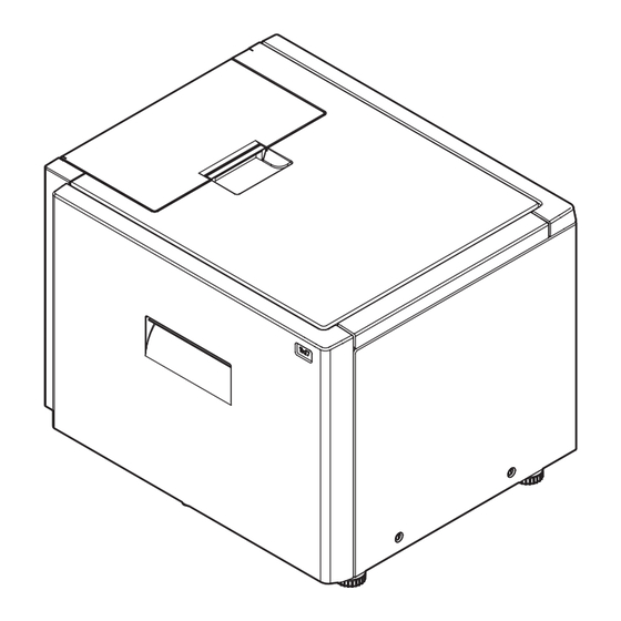
[1] PRODUCT OUTLINE MX-LCX3 Service Manual This model is a large capacity paper feed tray installed to the main unit. It stores 3,000 sheets, eliminating troublesome paper supply. MX-LCX3 MX-LCX3 PRODUCT OUTLINE 1 – 1... -
Page 4: Specifications
Kind/weight 106-209g/m 1(including 28+-56- lbs bond gloss paper) applicable 210-256g/m paper Cardboard 2 56-68 lbs bond 75-90g/m Envelope 20-24 lbs bond OHP paper Label paper Tab paper * : Available for products for China only. MX-LCX3 SPECIFICATIONS 2 – 1... -
Page 5: External Views And Internal Structures
Paper feed clutch Controls ON/OFF of the paper feed roller. CN-F 11pin ON: "L" OFF: "24V" LFAN LFAN Separation assist Brushless motor Assists feeding of paper. CN-D 15, 16pin ON: "L" OFF: "5V" MX-LCX3 EXTERNAL VIEWS AND INTERNAL STRUCTURES 4 – 1... -
Page 6: Pwb, Sensor, Switch, Heater
Other than Lower limit: "L" DOWN SW PWB — Lowering SW PWB unit Shifts the tray to the paper supply position. LTLLED LTLLED Tray LED The tray state is displayed with LED. MX-LCX3 EXTERNAL VIEWS AND INTERNAL STRUCTURES 4 – 2... -
Page 7: Operational Description
(Lift motor output) (Lower limit sensor) (Lower limit sensor) (Upper limit sensor) (Upper limit sensor) LPED LPED (Paper empty detection) (Paper empty detection) LPSL LTLSW (Solenoid) 1097 (Tray SW) Less than 542 (Encoder signal) (Encoder signal) MX-LCX3 OPERATIONAL DESCRIPTION 5 – 1... -
Page 8: Paper Feed Operation
Preliminary paper Preliminary paper Preliminary paper Preliminary paper Preliminary paper feed complete feed complete feed complete feed complete feed complete Paper feed start Paper feed start Paper feed start Paper feed start Paper feed start MX-LCX3 OPERATIONAL DESCRIPTION 5 – 2... -
Page 9: Paper Empty Detection
When the tray lifts and stops at the paper feed position and during paper feed operation, paper presence/empty is detected by the paper presence/empty sensor (LPED). When paper empty is detected in the tray during paper feeding, paper feeding is stopped. MX-LCX3 OPERATIONAL DESCRIPTION 5 – 3... -
Page 10: Disassembly And Assembly
Remove the pawl, and remove the pickup roller and the paper feed roller. Open the upper cover, and remove the screws. Loosen the screw, and remove the paper guide block. Remove the pawl, and remove the reverse roller. Remove the upper cabinet. MX-LCX3 DISASSEMBLY AND ASSEMBLY 6 – 1... - Page 11 Remove the left front cabinet. (Refer to "A. Paper feed unit") Remove the harness. Remove the screws, and remove the lift drive unit. Remove the screws from the left and right rail sections, and remove the tray unit from the rail. MX-LCX3 DISASSEMBLY AND ASSEMBLY 6 – 2...
-
Page 12: Major Parts Removal
C. Paper feed solenoid Remove the paper feed unit. (Refer to "2. Each unit removal") Remove the cover. Remove the screws, and remove the lift motor. Remove the screw, and remove the unit. Disconnect the connector. MX-LCX3 DISASSEMBLY AND ASSEMBLY 6 – 3... - Page 13 F. Handling solenoid Check that there is no paper, and lower the paper feed table to the lower limit with the main unit simulation mode. Pull out the tray. Remove the screws. Disconnect the connector. MX-LCX3 DISASSEMBLY AND ASSEMBLY 6 – 4...
- Page 14 Remove the clutch unit. Remove the E-ring, and remove the clutch. Remove the screws, and remove the solenoid. G. Clutch Remove the upper cabinet. Remove the rear cabinet. Remove the left rear cabinet. MX-LCX3 DISASSEMBLY AND ASSEMBLY 6 – 5...
-
Page 15: Maintenance
As a rough guide, the torque limiter should be replaced when the LCC paper ✕ ✕ Torque limiter feed counter reaches a value of 800K (Sim22-9). ✕ Each transport rollers Each transport paper guides Each gears ✕ ✕ Each belts ✕ ✕ Each sensors ✕ MX-LCX3 MAINTENANCE 7 – 1... -
Page 16: Adjustments
Change the adjustment value. Repeat the steps from 4) to 6) DUPLEX NO until the condition described in the step 6) is satisfied. After the adjustment is finished, escape from the simulation EXECUTE mode with the reset key. MX-LCX3 ADJUSTMENTS 8 – 1... - Page 17 ADU PLAIN PAPER(L) S: 50 ADU HEAVY PAPER1(S) T: 50 ADU HEAVY PAPER1(L) U: 50 A4LCC V: 60 A3LCC(S) W: 50 A3LCC(L) X: 50 A3LCC HEAVY PAPER‚P(S) Y: 50 A3LCC HEAVY PAPER‚P(L) REGI1 REGI2 ENGIN MX-LCX3 ADJUSTMENTS 8 – 2...
- Page 18 <Notation of (Large size), (Small size)> (Small size): Length of paper in the feeding direction is not more than LT size (216mm). (Large size): Length of paper in the feeding direction exceeds LT size (216mm). MX-LCX3 ADJUSTMENTS 8 – 3...
- Page 19 0.1mm. Repeat the steps from 4) to 6) until the condition shown in the step 5) is satisfied. EXECUTE After the adjustment is finished, escape from the simulation mode with the reset key. MX-LCX3 ADJUSTMENTS 8 – 4...
- Page 20 1 to 6 (CS1) Cassette 3 Cassette 4 Selected Double-sided print DUPLEX 0 to 1 selection (NO) Not selected * The item name for the items J and K is detailed display. Example: PAPER: CS1 MX-LCX3 ADJUSTMENTS 8 – 5...
-
Page 21: Simulation
LCC tray lift SW LTLD LCC tray lock sensor LIPSW LCC illegal paper detection SW LTOD LCC main unit connection sensor SIMULATION NO.04-02 CLOSE TEST LCC SENSOR CHECK LPFD LPED EXECUTE LDSW L24VM LLSW LTOD MX-LCX3 SIMULATION 9 – 1... - Page 22 1) Press [EXECUTE] key. 2) Press [YES] key to execute cancellation of the trouble. SIMULATION NO.04-05 CLOSE TEST LCC SYNCRONIZING SIGNAL CHECK CLOSE SIMULATION NO.15 TEST LTRC LTRC OFF LCC TROUBLE CANCELLATION ARE YOU SURE? EXECUTE MX-LCX3 SIMULATION 9 – 2...
-
Page 23: Self Diag Message And Trouble Code
Some other troubles must be cleared by a simula- tion. Some warning messages of consumable parts are automatically cleared when the trouble is repaired. Some other warning mes- sages must be cleared by a simulation. MX-LCX3 SELF DIAG MESSAGE AND TROUBLE CODE 10 – 1... -
Page 24: Trouble Code List
Check Connect the MX-LCX3. Check Check the connector and the harness of the power Remedy line. Check that the power unit and the LCC control Remedy PWB is of 24V. MX-LCX3 SELF DIAG MESSAGE AND TROUBLE CODE 10 – 2... - Page 25 M E M O MX-LCX3 SELF DIAG MESSAGE AND TROUBLE CODE 10 – 3...
-
Page 26: Electrical Section
LTLSL LTLS N.C. LTLSU Cassette unit side harness A3 CD SMP-03V-NC SMR-03V-N LFAN1 LFAN2 LFAN1 Cassette unit front harness A3 CD SMP-03V-NC SMR-03V-N Cassette unit Cassette relay harness CD LFAN2 rear harness A3 CD MX-LCX3 ELECTRICAL SECTION 11 – 1... -
Page 27: Paper Feed Unit
B9B-PH-K-S +5VR +5VR CN-G LPUD B5B-PH-K-S PHR-5 PHR-5 +24V +24V GND1 LPFM LPFM LPFM LCC transport motor LPFM-T LPFM-T LPFM-CLK LPFM-CLK CN-D B18B-PHDSS +5VR LTLLED LTLSW LTLD N.C. 24V-ICP LTLSL N.C. LTLSU LFAN1 LFAN2 MX-LCX3 ELECTRICAL SECTION 11 – 2... -
Page 28: Block Diagram
LCC paper feed clutch(LPFC) LCC paper feed IC protector clutch(LTRC) ICP-N15 +24V LCC tray lock solenoid Solenoid clutch drive circuit Lock release(LTLSU) IC protector ICP-N20 Lock(LTLSL) LCC paper feed solenoid(LPFS) IC protector ICP-N15 A3-LCC P A3-LCC MX-LCX3 ELECTRICAL SECTION 11 – 3... - Page 29 LCC tary upper limit sensor(LUD) LCC tary lower limit sensor(LDD) LCC tary paper empty sensor(LPED) LCC transport sensor(LPFD) Sensor input circuit LCC main unit connection sensor(LTOD) LCC lift motor encoder sensor(LRE) LCC tray lock sensor(LTLD) C PWB MX-LCX3 ELECTRICAL SECTION 11 – 4...
-
Page 30: Circuit Diagram
104Z/16V 104Z/16V B18B-PHDSS-B B18B-PHDSS-B RT1N141C x 3 RES_LCC RT1N141C x 2 /TXD_LCC CN-W CN-W /LTLLED +5VR B14B-PHDSS-B B14B-PHDSS-B /LTLSW N.C. /LTLD /RES_LCC /LTLSL +24V-ICP /NMI /LTLSU N.C. +24V +24V /FAN2 /FAN1 TXD_LCC RXD_LCC N.C. MX-LCX3 ELECTRICAL SECTION 11 – 5... - Page 31 47uF/16V 47uF/35V 47uF/35V 104Z/16V 104Z/16V 223K/50V(1608) 223K/50V(1608) DAP202K x 2 N141C x 3 N.C. S_LCC /TRC_LCC D_LCC RES_LCC CN-W CN-W /DSR_LCC B12B-PASK B12B-PASK /DTR_LCC B14B-PHDSS-B B14B-PHDSS-B /RXD_LCC CN-A CN-A /TXD_LCC S_LCC +24V D_LCC D_LCC MX-LCX3 ELECTRICAL SECTION 11 – 6...
- Page 32 LEAD-FREE SOLDER The PWB’s of this model employs lead-free solder. The “LF” marks indicated on the PWB’s and the Service Manual mean “Lead-Free” solder. The alphabet following the LF mark shows the kind of lead-free solder. Example: <Solder composition code of lead-free solder> Solder composition Solder composition code Solder composition...
- Page 33 * Applicable to battery-operated equipment * Applicable to battery-operated equipment...
- Page 34 SHARP CORPORATION Digital Document System Group CS Promotion Center Yamatokoriyama, Nara 639-1186, Japan 2006 June Printed in Japan...
Need help?
Do you have a question about the MX-LCX3 and is the answer not in the manual?
Questions and answers