Table of Contents
Advertisement
Service
Manual
6 ch POWER AMPLIFIER
GM-2137
VEHICLE
Lincoln Navigator
Lincoln Aviator
Lincoln Town Car
Ford Ranger (Tremor ")
Ford Sport Track (Adrenalin)
For details, refer to "Important symbols for good services".
PIONEER CORPORATION
PIONEER ELECTRONICS (USA) INC.
PIONEER EUROPE NV
Haven 1087 Keetberglaan 1, 9120 Melsele, Belgium
PIONEER ELECTRONICS ASIACENTRE PTE.LTD. 253 Alexandra Road, #04-01, Singapore 159936
C PIONEER CORPORATION 2004
FORD
GM-2137ZF/X1R/UC
DESTINATION
PRODUCED AFTER
U.S.A., CANADA
October 2003
4-1, Meguro 1-Chome, Meguro-ku, Tokyo 153-8654, Japan
P.O.Box 1760, Long Beach, CA 90801-1760 U.S.A.
ZF
X1R/UC
FORD PART No.
ID No. PIONEER MODEL No.
4L7T-18C808-AD
K-ZZB. JAN. 2004 Printed in Japan
ORDER NO.
CRT3216
GM-2137ZF/X1R/UC
Advertisement
Table of Contents

Subscribe to Our Youtube Channel
Related Manuals for Pioneer GM-2137ZF/X1R/UC


Summary of Contents for Pioneer GM-2137ZF/X1R/UC
-
Page 1: Service Manual
PIONEER ELECTRONICS (USA) INC. P.O.Box 1760, Long Beach, CA 90801-1760 U.S.A. PIONEER EUROPE NV Haven 1087 Keetberglaan 1, 9120 Melsele, Belgium PIONEER ELECTRONICS ASIACENTRE PTE.LTD. 253 Alexandra Road, #04-01, Singapore 159936 C PIONEER CORPORATION 2004 K-ZZB. JAN. 2004 Printed in Japan... -
Page 2: Table Of Contents
2.1 PACKING..............3 7.1 DIAGNOSIS ............18 2.2 EXTERIOR ............4 7.1.1 DISASSEMBLY.........18 3. SCHEMATIC DIAGRAM..........6 7.1.2 ..19 CONNECTOR FUNCTION DESCRIPTION 3.1 SCHEMATIC DIAGRAM(GUIDE PAGE) ....6 7.2 IC ................20 4. PCB CONNECTION DIAGRAM........12 7.3 SYSTEM BLOCK DIAGRAM......21 4.1 AMP UNIT............12 8. OPERATIONS ............22 GM-2137ZF/X1R/UC... -
Page 3: Specifications
- For the applying amount of lubricants or glue, follow the instructions in this manual. ( In the case of no amount instructions, apply as you think it appropriate.) - PACKING SECTION PARTS LIST Mark No. Description Part No. 1 Carton HHG0438 2 Pad HHW0052 3 Pad HHW0051 GM-2137ZF/X1R/UC... -
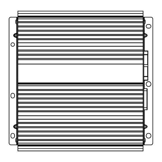
Page 4: Exterior
2.2 EXTERIOR GM-2137ZF/X1R/UC... - Page 5 HBA0027 3 Screw(M3x5) HBA0028 4 Case HNB0200 5 Panel HNB0201 6 Panel HNB0202 7 Holder HNC0140 8 Heat Sink HNR0225 9 Spacer HNV0016 10 Amp Unit HWM0101 11 Terminal(CN103) CKF1059 12 Connector(CN102) HKE0040 13 Connector(CN101) HKM0004 14 Holder HNC0141 GM-2137ZF/X1R/UC...
-
Page 6: Schematic Diagram
Note: When ordering service parts, be sure to refer to " EXPLODED VIEWS AND PARTS LIST" or "ELECTRICAL PARTS LIST". Large size SCH diagram Guide page Detailed page SUB L- SUB L+ SUB R- SUB R+ SUB L- SUB L+ SUB R+ SUB R- POWER GND Subwoofer Clip Detect AMP Enable / Clip Detect GM-2137ZF/X1R/UC... - Page 7 Symbol indicates a resistor. Decimal points for resistor No differentiation is made between chip resistors and and capacitor fixed values discrete resistors. are expressed as : Symbol indicates a capacitor. No differentiation is made between chip capacitors and 0.022 R022 discrete capacitors. GM-2137ZF/X1R/UC...
- Page 8 GM-2137ZF/X1R/UC...
- Page 9 GM-2137ZF/X1R/UC...
- Page 10 GM-2137ZF/X1R/UC...
- Page 11 GM-2137ZF/X1R/UC...
-
Page 12: Pcb Connection Diagram
1.The parts mounted on this PCB Capacitor Connector include all necessary parts for several destination. For further information for SIDE A respective destinations, be sure to check with the schematic dia- gram. SIDE B P.C.Board Chip Part AMP UNIT GM-2137ZF/X1R/UC... - Page 13 SIDE A FRONT GM-2137ZF/X1R/UC...
- Page 14 AMP UNIT GM-2137ZF/X1R/UC...
- Page 15 SIDE B GM-2137ZF/X1R/UC...
-
Page 16: Electrical Parts List
Diode MTZJ4R3(C) RS1/16S222J Diode HZS7L(A2) RS1/16S102J Diode HZS3LL(A) RS1/16S103J RS1/16S332J Diode HZS3LL(B) RS1/16S103J Diode 1SS133 Diode 1SS133 RS1/16S332J Diode 1SS133 RS1/16S472J Diode 1SS133 RS1/16S332J RS1/16S222J Choke Coil 0.3mH HTH0001 RS1/16S331J Choke Coil 0.3mH HTH0001 RS1/16S472J RS1/16S472J RS1/16S103J RS1/16S122J RS1/16S101J GM-2137ZF/X1R/UC... - Page 17 CEJQ220M16 CCSRCH101J50 CKCYF103Z50 4700µF/16V HCH0009 CEJQ220M16 CKCYF103Z50 CCSRCH101J50 CKCYF103Z50 CKSRYB104K25 CKSRYB103K50 CKSRYB104K25 CKSRYB104K25 CEAT331M16 CKSRYB103K50 CCSRCH101J50 CEJQ100M16 CCSRCH101J50 CKSRYB102K50 CCSRCH101J50 CEJQ221M10 CCSRCH101J50 CCSRCH101J50 CKSRYB103K50 CEJQ220M16 CCSRCH101J50 CEJQ1R0M50 CCSRCH101J50 CKSRYB102K50 CCSRCH101J50 CKSRYB104K25 CCSRCH101J50 CCSRCH101J50 CEJQ101M16 CCSRCH101J50 CCSRCH101J50 CKSRYB104K25 CKSRYB104K25 CKSRYB104K25 GM-2137ZF/X1R/UC...
-
Page 18: Adjustment
Removing the Amp Unit (Fig.2) Panel Holder Remove the four screws and then remove the Panel. Remove the eight screws and then remove the two Holders. Remove the nine screws and then remove the Amp Unit. Holder Amp Unit Fig.2 GM-2137ZF/X1R/UC... -
Page 19: Connector Function Description
7.1.2 CONNECTOR FUNCTION DESCRIPTION 16 15 14 13 12 11 10 SUB L+ SUB L- Subwoofer Clip Detect POWER GND SUB R- SUB R+ SUB L- SUB L+ SUB R+ SUB R- AMP Enable/Clip Detect POWER GND GM-2137ZF/X1R/UC... - Page 20 7.2 IC TDA1562ST MODE PGND1 OUT- PGND2 VREF STAT SGND GM-2137ZF/X1R/UC...
-
Page 21: System Block Diagram
7.3 SYSTEM BLOCK DIAGRAM GM-2137ZF/X1R/UC... -
Page 22: Operations
8. OPERATIONS There is no information to be shown in this chapter. GM-2137ZF/X1R/UC...
Need help?
Do you have a question about the GM-2137ZF/X1R/UC and is the answer not in the manual?
Questions and answers