Table of Contents
Advertisement
Quick Links
Service
Manual
SUB-WOOFER AMPLIFIER
GM-2037
VEHICLE
DESTINATION
RANGER
North America
For details, refer to "Important symbols for good services".
PIONEER CORPORATION
PIONEER ELECTRONICS (USA) INC.
PIONEER EUROPE NV
Haven 1087 Keetberglaan 1, 9120 Melsele, Belgium
PIONEER ELECTRONICS ASIACENTRE PTE.LTD. 253 Alexandra Road, #04-01, Singapore 159936
C PIONEER CORPORATION 2003
GM-2037ZF/X1R/UC
PRODUCED AFTER
August 2003
4-1, Meguro 1-Chome, Meguro-ku, Tokyo 153-8654, Japan
P.O.Box 1760, Long Beach, CA 90801-1760 U.S.A.
ZF
X1R/UC
FORD PART No.
ID No.
4L5T-18C808-AB
K-ZZB. JUNE 2003 Printed in Japan
ORDER NO.
CRT3066
PIONEER MODEL No.
GM-2037ZF/X1R/UC
Advertisement
Table of Contents

Related Manuals for Pioneer gM-2037ZF


Summary of Contents for Pioneer gM-2037ZF
-
Page 1: Service Manual
PIONEER ELECTRONICS (USA) INC. P.O.Box 1760, Long Beach, CA 90801-1760 U.S.A. PIONEER EUROPE NV Haven 1087 Keetberglaan 1, 9120 Melsele, Belgium PIONEER ELECTRONICS ASIACENTRE PTE.LTD. 253 Alexandra Road, #04-01, Singapore 159936 C PIONEER CORPORATION 2003 K-ZZB. JUNE 2003 Printed in Japan... -
Page 2: Safety Information
Improperly performed repairs can adversely affect the safety and reliability of the product and may void the warranty. If you are not qualified to perform the repair of this product properly and safely, you should not risk trying to do so and refer the repair to a qualified service technician. GM-2037ZF/X1R/UC... -
Page 3: Table Of Contents
Rated power ....35W or less (1.5Ω, f=100Hz, THD+N=2%, 80kHz LPF) Residual noise ... . .0.5mV or more (Rg=1k ohm IHF-A) Output offset voltage ..0±100mV or less (Output + - both terminal voltage) GM-2037ZF/X1R/UC... -
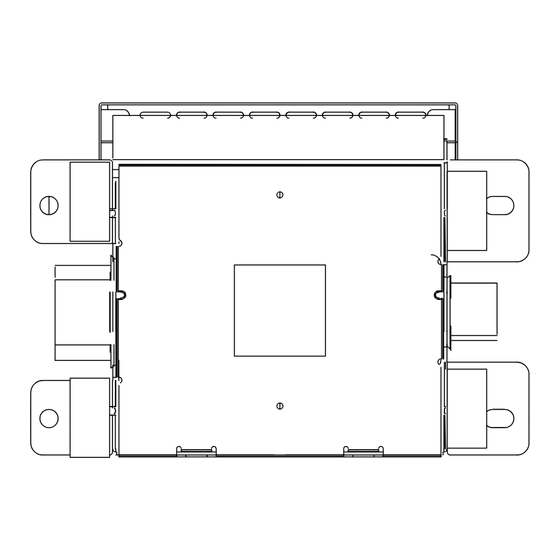
Page 4: Exploded Views And Parts List
2. EXPLODED VIEWS AND PARTS LIST 2.1 EXTERIOR GM-2037ZF/X1R/UC... - Page 5 HNA0003 3 Screw IMS30P050FMC 4 Screw PPZ40P080SAD 5 Case HNB0139 6 Holder HNC0088 7 Shield HNC0127 8 Heat Sink HNR0186 9 Mother Unit HWM0083 10 Connector(CN101) HKE0038 11 Connector(CN102) HKE0039 12 IC(IC200) PAL006A 13 Cushion HNM0145 14 Cushion HNM6623 GM-2037ZF/X1R/UC...
-
Page 6: Schematic Diagram
3. SCHEMATIC DIAGRAM 3.1 OVERALL CONNECTION DIAGRAM GAIN:-2.3dB GM-2037ZF/X1R/UC... - Page 7 No differentiation is made between chip resistors and discrete resistors. Symbol indicates a capacitor. No differentiation is made between chip capacitors and discrete capacitors. Decimal points for resistor and capacitor fixed values are expressed as : ← ← 0.022 R022 GM-2037ZF/X1R/UC...
-
Page 8: Pcb Connection Diagram
4. PCB CONNECTION DIAGRAM 4.1 MOTHER UNIT SIDE A MOTHER UNIT GM-2037ZF/X1R/UC... - Page 9 SIDE B MOTHER UNIT GM-2037ZF/X1R/UC...
-
Page 10: Electrical Parts List
CCSRCH101J50 RESISTORS CCSRCH101J50 CFTNA224J50 RD1/4PU432J CFTNA224J50 RD1/4PU432J 4700µF/16V HCH0009 RS1/16S332J CKCYF103Z50 RS1/16S332J RS1/16S103J CKCYF103Z50 CEJQ3R3M50 RS1/16S472J CEJQ101M16 RD1/4PU472J CEJQ330M16 RS1/16S332J CKSRYB473K50 RD1/4PU102J RS1/16S222J CEJQ221M10 CKSRYB103K50 RS1/16S102J CKSRYB103K50 RS1/16S103J CEJQ101M6R3 RS1/16S103J CEJQ1R0M50 RS1/16S103J RS1/16S103J CEJQ220M16 RS1/16S101J RS1/16S103J RS1/16S103J RS1/16S103J RS1/16S331J GM-2037ZF/X1R/UC... -
Page 11: Adjustment
Removing the Case (not shown) 1. Remove the Case. Removing the Mother Unit (Fig.1) Remove the four screws and then remove the Heat Sink. Remove the three screws and then remove the Mother Unit. Mother Unit Heat Sink Fig.1 GM-2037ZF/X1R/UC... -
Page 12: Connector Function Description
2. GND 3. GND 4. +B 5. +B 6. NC 7. AUDIO IN + 8. AUDIO IN - 9. NC 10. NC 1. OUT1 + 2. OUT1 - 3. OUT2 + 4. OUT2 - 5. OUT1 + 6. OUT2 + GM-2037ZF/X1R/UC... -
Page 13: Operations
7.2 IC NJM2068M A OUT B OUT A -IN B -IN A +IN B +IN 8. OPERATIONS There is no information to be shown in this chapter. GM-2037ZF/X1R/UC...
Need help?
Do you have a question about the gM-2037ZF and is the answer not in the manual?
Questions and answers