Table of Contents
Advertisement
Service
Manual
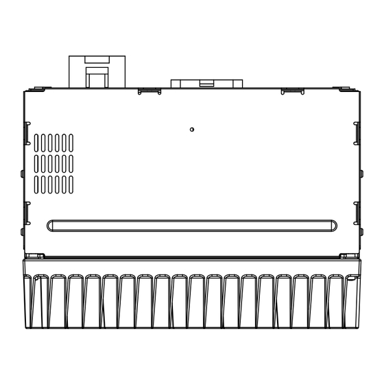
6 CHANNEL POWER AMPLIFIER
GM-2047
VEHICLE
DESTINATION
Chevy Cobalt
North America
For details, refer to "Important symbols for good services".
PIONEER CORPORATION
PIONEER ELECTRONICS (USA) INC.
PIONEER EUROPE NV
Haven 1087 Keetberglaan 1, 9120 Melsele, Belgium
PIONEER ELECTRONICS ASIACENTRE PTE.LTD. 253 Alexandra Road, #04-01, Singapore 159936
C PIONEER CORPORATION 2004
GENERAL MOTORS
GM-2047ZG/X1R/UC
PRODUCED AFTER
October 2004
4-1, Meguro 1-Chome, Meguro-ku, Tokyo 153-8654, Japan
P.O.Box 1760, Long Beach, CA 90801-1760 U.S.A.
ZG
/X1R/UC
PART No.
ID No.
22699257
K-ZZB. AUG. 2004 Printed in Japan
ORDER NO.
CRT3338
PIONEER MODEL No.
GM-2047ZG/X1R/UC
Advertisement
Table of Contents

Related Manuals for Pioneer GM-2047ZG


Summary of Contents for Pioneer GM-2047ZG
-
Page 1: Service Manual
PIONEER ELECTRONICS (USA) INC. P.O.Box 1760, Long Beach, CA 90801-1760 U.S.A. PIONEER EUROPE NV Haven 1087 Keetberglaan 1, 9120 Melsele, Belgium PIONEER ELECTRONICS ASIACENTRE PTE.LTD. 253 Alexandra Road, #04-01, Singapore 159936 C PIONEER CORPORATION 2004 K-ZZB. AUG. 2004 Printed in Japan... -
Page 2: Safety Information
By following the instructions in this manual, be sure to apply the prescribed grease or glue to proper portions by the appropriate amount.For replacement parts or tools, the prescribed ones should be used. GM-2047ZG/X1R/UC... -
Page 3: Table Of Contents
Frequency response (Rear) ..........+ 2.4 ± 3.0 dB (100 kHz / 1 kHz ref.) Frequency response (Subwoofer)........- 4.3 ± 3.0 dB (100 Hz / 80 Hz ref.) Distortion ..................1.0 % or less (10 W, 1 kHz) Separation .................... 50 dB or more (1 kHz) GM-2047ZG/X1R/UC... -
Page 4: Exploded Views And Parts List
( In the case of no amount instructions, apply as you think it appropriate.) - PACKING SECTION PARTS LIST Mark No. Description Part No. 1 Protector HHP0237 2 Protector HHP0239 3 Protector HHP0240 4 Protector HHP0238 5 Contain Box HHL0423 GM-2047ZG/X1R/UC... -
Page 5: Exterior
Mark No. Description Part No. 1 Screw BMZ26P200FTC 6 Connector(CN801) HKE0028 2 Screw BMZ30P050FTC 7 Connector(CN802) HKE0029 3 Case HNB0205 8 Holder HNC0057 4 Heat Sink HNR0285 9 Screw PPZ40P080SAD 5 Amp Unit HWM0105 10 Chassis Unit HXA0401 11 Screw IMS30P050FTC GM-2047ZG/X1R/UC... -
Page 6: Schematic Diagram
No differentiation is made between chip resistors and and capacitor fixed values discrete resistors. are expressed as : ← Symbol indicates a capacitor. No differentiation is made between chip capacitors and ← 0.022 R022 discrete capacitors. Guide page Detailed page GM-2047ZG/X1R/UC... - Page 7 AMP UNIT GM-2047ZG/X1R/UC...
- Page 8 GM-2047ZG/X1R/UC...
- Page 9 GM-2047ZG/X1R/UC...
- Page 10 GM-2047ZG/X1R/UC...
- Page 11 GM-2047ZG/X1R/UC...
-
Page 12: Pcb Connection Diagram
1.The parts mounted on this PCB include all necessary parts for Capacitor Connector several destination. For further information for SIDE A respective destinations, be sure to check with the schematic dia- gram. SIDE B P.C.Board Chip Part AMP UNIT 13 14 FRONT GM-2047ZG/X1R/UC... -
Page 13: Gm-2047Zg/X1R/Uc
SIDE A 15 16 17 18 19 20 21 22 23 24 10 11 12 RONT GM-2047ZG/X1R/UC... -
Page 14: Gm-2047Zg/X1R/Uc
AMP UNIT GM-2047ZG/X1R/UC... - Page 15 SIDE B GM-2047ZG/X1R/UC...
-
Page 16: Electrical Parts List
RS1/16S683J Transistor 2SC2458 RS1/16S122J Transistor 2SB1238 RS1/16S122J Transistor DTA114EU RS1/16S332J Transistor 2SC4081 RS1/16S332J Diode RM4Z-LFJ4 RS1/16S221J Diode 1SS133 RS1/16S221J Diode UDZS6R8(B) RS1/16S683J Diode ERA15-02VH RS1/16S683J Diode ERA15-02VH RS1/16S122J Diode MTZJ4R3(C) RS1/16S122J Diode MTZJ5R6(B) RS1/16S332J Diode ERA15-02VH RS1/16S332J Diode ERA15-02VH GM-2047ZG/X1R/UC... - Page 17 CCSRCH181J50 RS1/16S683J CCSRCH181J50 RS1/16S122J CCSRCH181J50 RS1/16S122J CCSRCH181J50 RS1/16S332J CCSRCH181J50 RS1/16S332J CCSRCH181J50 RS1/16S472J CCSRCH181J50 RS1/16S472J CCSRCH181J50 RS1/16S153J CEJQ100M16 RS1/16S153J CEJQ100M16 CEJQ100M16 RS1/16S393J RS1/16S393J CEJQ100M16 RS1/16S472J CEJQ100M16 RS1/16S472J CEJQ100M16 RS1/16S332J CEJQ100M16 RS1/16S332J CEJQ100M16 RS1/16S181J CCSRCH101J50 RS1/16S181J CCSRCH101J50 RS1/16S102J CCSRCH101J50 RS1/16S102J CCSRCH101J50 GM-2047ZG/X1R/UC...
- Page 18 CEJQ1R0M50 CKSRYB333K25 CKSRYB102K50 CKSRYB153K25 CKSRYB102K50 CKSRYB153K25 CEJQ1R0M50 CKSRYB183K50 CKSRYB102K50 CKSRYB183K50 CKSRYB102K50 CKSRYB562K50 CKSRYB102K50 CKSRYB562K50 CKSRYB102K50 CKSRYB332K50 CKSRYB102K50 CKSRYB332K50 CKSRYB102K50 CKSRYB332K50 CKSRYB102K50 CKSRYB332K50 CKSRYB102K50 CKSRYB102K50 CKSRYB102K50 CKSRYB102K50 CKSRYB102K50 CCSRCH271J50 CKSRYB102K50 CCSRCH271J50 CKSRYB102K50 CKSRYB104K16 CKSRYB104K16 CKSRYB104K16 CKSRYB104K16 CEHAR100M16 CEHAR100M16 CEHAR101M10 CEHAR101M10 GM-2047ZG/X1R/UC...
-
Page 19: Adjustment
Heat Sink Remove the ten screws. Remove the four screws and then remove the Heat Sink. Fig.1 Removing the Amp Unit (Fig.2) Remove the two screws. Remove the three screws and then remove the Amp Unit. Amp Unit Fig.2 GM-2047ZG/X1R/UC... -
Page 20: Connector Function Description
20. NC 21. NC 22. NC 23. LFN 24. LFP 1. PWR 2. PWR 3. NC 4. AMP ENABLE 5. GND 6. GND 7. NC 8. MUTE 8. OPERATIONS There is no information to be shown in this chapter. GM-2047ZG/X1R/UC...
Need help?
Do you have a question about the GM-2047ZG and is the answer not in the manual?
Questions and answers