
Subscribe to Our Youtube Channel
Related Manuals for Sony TRINITRON KV-T25SZ8


Summary of Contents for Sony TRINITRON KV-T25SZ8
-
Page 1: Service Manual
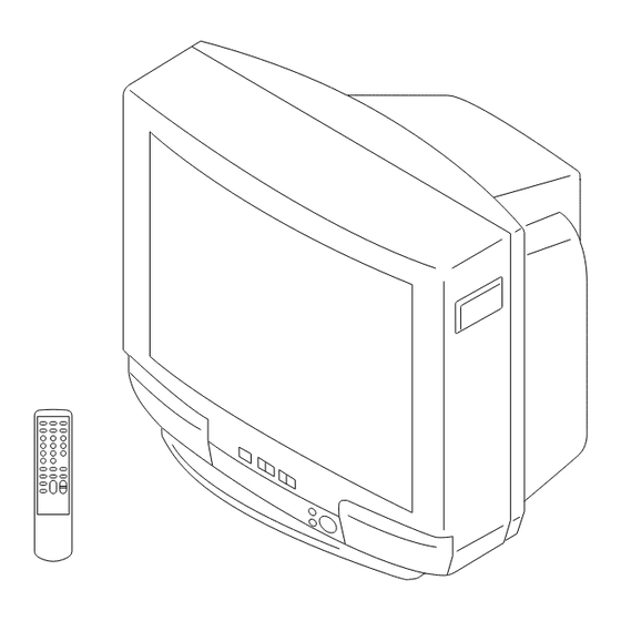
SERVICE MANUAL BG-1S CHASSIS MODEL COMMANDER DEST. CHASSIS NO. MODEL COMMANDER DEST. CHASSIS NO. KV-T25SZ8 RM-870 Australia SCC-J99F-A TRINITRON COLOR TV ®... - Page 2 CARBON PAINTED ON THE CRT, AFTER REMOVING THE PARTS LIST ARE CRITICAL TO SAFE OPERATION. REPLACE ANODE. THESE COMPONENTS WITH SONY PARTS WHOSE PART NUMBERS APPEAR AS SHOWN IN THIS MANUAL OR IN SUPPLEMENTS PUBLISHED BY SONY. – 2 –...
-
Page 3: Table Of Contents
KV-T25SZ8 RM-870 TABLE OF CONTENTS Section Title Page Section Title Page 6. DIAGRAMS 1. GENERAL ..............6-1. Block Diagram ............2. DISASSEMBLY 6-2. Circuit Boards Location ........2-1. Rear Cover Removal ..........6-3. Schematic Diagrams and Printed Wiring Boards. (1) Schematic Diagram of A Board ...... -
Page 4: General
SECTION 1 The operating instructions mentioned here are partial abstracts from the Operating Instructions Manual. The page numbers of the Operating GENERAL Instruction Manual remain as in this manual. AUTO PROGR AUTO PROGR... - Page 5 Getting Started Front of TV Connections Camcorder VIDEO INPUT VIDEO AUDIO L (MONO) to video and audio outputs : Signal flow Connecting a VHF antenna or a combination VHF/UHF antenna When using the video input jacks — 75-ohm coaxial cable (round) Do not connect video equipment to the video input jacks at the front and the rear of your TV simultaneously;...
-
Page 6: Tv System Button Is Not Used For This Model
Operations Presetting channels Presetting channels Presetting channels manually Watching the TV Switching off the TV To switch off the TV temporarily, press POWER on the To change the channel for a particular program remote commander. position or to receive a channel with a weak signal, preset the channel manually. -
Page 7: And Sound Settings
The last TV program position or video mode just before the TV Each time you press SELECT, the screen changes as Displaying on-screen information Adjusting the picture turns into standby mode will appear when the TV is turned on follows: using the Wake Up Timer. - Page 8 Additional Information No picture Troubleshooting Selecting a stereo or No sound bilingual program / Press POWER. / Check the antenna connection. / Check the VCR connections. / Check the power cord connection. Press A/B/ENLARGE repeatedly until you If you have any problems, read this manual again and / Check the standby mode.
-
Page 9: Disassembly
SECTION 2 DISASSEMBLY 2-1. REAR COVER REMOVAL 2-3. F1 BOARD REMOVAL F1 board 2 Two screws (BVTP 4 16) 3 One screw (BVTP 3 16) 1 Two screws (BVTP 4 16) 2-2. A BOARD REMOVAL 2-4. SERVICE POSITION A board Lever Lever A board... -
Page 10: Replacement Of Parts
2-5. REPLACEMENT OF PARTS 2-6. DEMAGNETIZATION COIL REMOVAL For replacement of the Multi Button, Power Button and Light Guide, cut the welded portions from them, exchange with the new parts, and fix them with screws (+BVTP) respectively. 2-5-1. REPLACEMENT OF MULTI BUTTON 2 DGC holder Remove the claw Two screws... -
Page 11: Picture Tube Removal
2-7. PICTURE TUBE REMOVAL 3 F1 board 4 C board 7 VM board 5 Deflection yoke 2 A board 2 Using a thumb press down then pull up the rubber cap firmly in the direction indicated by the arrow b. 6 Four screws (Tapping screws) 1 Anode cap... -
Page 12: Set-Up Adjustments
KV-T25SZ8 RM-870 SECTION 3 SET-UP ADJUSTMENTS The following adjustments should be made when a complete Perform the adjustments in the following order : realignment is required or a new picture tube is installed. 1. Beam Landing These adjustments should be performed with rated power 2. -
Page 13: Convergence
KV-T25SZ8 RM-870 3-2. CONVERGENCE Operation of the V.STAT magnet. Preparation : If the V-STAT magnet is moved in the direction of the a and Before starting this adjustment, adjust the focus, horizontal size b arrows, the red, green and blue dots move as shown below. - Page 14 KV-T25SZ8 RM-870 (2) Dynamic Convergence Adjustment Preparation : Before starting this adjustment, adjust the horizontal static 3. Move the deflection yoke as shown in the figure below and convergence and the vertical static convergence. optimize the convergence. 1. Slightly loosen the deflection yoke screws.
-
Page 15: Focus Adjustment
KV-T25SZ8 RM-870 DATA 3-3. FOCUS ADJUSTMENT Adjust FOCUS control on the flyback transformer for the best SERVICE focus. Adjustment Item Item number WRITE MUTING Executes the writing Focus a. AN ITEM OF ADJUSTMENT 3-4. G2 (SCREEN) AND WHITE BALANCE ADJUSTMENTS... -
Page 16: Self Diagnosis Function
KV-T25SZ8 RM-870 SECTION 4 SELF DIAGNOSIS FUNCTION If no acknowledgement is returned from a device which is turned "ON", the device has a problem. In this case, one of the LED's responding to the problem device will flicker a defined number of times. -
Page 17: Circuit Adjustments
KV-T25SZ8 SECTION 5 RM-870 CIRCUIT ADJUSTMENTS 5-1. ADJUSTMENTS WITH COMMANDER Service adjustments are made with the RM-870 that comes with this unit. [1], [4] Raise/lower the service item number [3], [6] Raise/lower the data [MUTING] Writes Entering service mode Executes the writing... -
Page 18: Adjustment Method
KV-T25SZ8 RM-870 5-2. ADJUSTMENT METHOD Item Number 08 Use the same method for Items Number 00-4B. Use [1] and [4] to This explanation uses V-SHIFT as an example. select the adjustment item, use [3] and [6] to adjust, write with 1. - Page 19 KV-T25SZ8 RM-870 Adjustment Item Table Item Adjustment Data Initial Standard data Note Device range number Item data 00–3F 50: 1F 60: 1F H SHIFT TDA8375 00–3F 50: 1F 60: 1F H SIZE TDA8375 00–3F 50: 2E 60: 2D PIN AMPLITUDE TDA8375 00–3F...
- Page 20 KV-T25SZ8 RM-870 Adjustment Item Table Item Adjustment Data Initial Standard data Note Device range number Item data 00–3F BLK OFF PICTURE CXP85200 00–3F H BLK LEFT WIDTH CXP85200 00–3F H BLK RIGHT WIDTH CXP85200 00–7F V BLK HIGHT WIDTH CXP85200 00–FF...
-
Page 21: A Board Adjustment After Ic003 (Memory) Replacement
KV-T25SZ8 RM-870 5-3. A BOARD ADJUSTMENT AFTER IC003 5-4. PICTURE DISTORTION ADJUSTMENT (MEMORY) REPLACEMENT Item Number 00 – 08 1. Enter to Service Mode. HSF (H SHIFT) 00 HSF (H SHIFT) 2. Press commander buttons [5] and [0] (Data Initialize), and [2] and [0] (Data Copy) to initialize the data. - Page 22 KV-T25SZ8 RM-870 MEMO – 22 –...
-
Page 23: Diagrams 6-1. Block Diagram
KV-T25SZ8 KV-T25SZ8 RM-870 RM-870 SECTION 7 EXPLODED VIEW NOTE: Items with no part number and no Items marked " * " are not stocked since The components identified by they are seldom required for routine shading and mark ! are critical description are not stocked because they are seldom required for routine service. -
Page 24: Electrical Parts List
KV-T25SZ8 RM-870 SECTION 8 The components identified by shading ELECTRICAL PARTS LIST and mark ! are critical for safety. Replace only with part number specified. NOTE: REF. NO. PART NO. DESCRIPTION REMARK REF. NO. PART NO. DESCRIPTION REMARK Items marked "... - Page 25 KV-T25SZ8 RM-870 The components identified by shading and mark ! are critical for safety. Replace only with part number specified. REF. NO. PART NO. DESCRIPTION REMARK REF. NO. PART NO. DESCRIPTION REMARK C236 1-126-968-11 ELECT 100MF C370 1-164-004-11 CERAMIC CHIP 0.1MF...
- Page 26 KV-T25SZ8 RM-870 The components identified by shading and mark ! are critical for safety. Replace only with part number specified. REF. NO. PART NO. DESCRIPTION REMARK REF. NO. PART NO. DESCRIPTION REMARK C806 1-126-960-11 ELECT CN111 * 1-564-505-11 PLUG, CONNECTOR 2P...
-
Page 27: Circuit Boards Location
KV-T25SZ8 RM-870 The components identified by shading and mark ! are critical for safety. Replace only with part number specified. REF. NO. PART NO. DESCRIPTION REMARK REF. NO. PART NO. DESCRIPTION REMARK D851 8-719-302-43 DIODE EL1Z <CHIP CONDUCTOR> D852 8-719-028-72... - Page 28 KV-T25SZ8 RM-870 The components identified by shading and mark ! are critical for safety. Replace only with part number specified. REF. NO. PART NO. DESCRIPTION REMARK REF. NO. PART NO. DESCRIPTION REMARK Q1201 8-729-422-27 TRANSISTOR 2SD601A-Q R071 1-216-037-00 RES,CHIP 1/10W...
- Page 29 KV-T25SZ8 RM-870 The components identified by shading and mark ! are critical for safety. Replace only with part number specified. REF. NO. PART NO. DESCRIPTION REMARK REF. NO. PART NO. DESCRIPTION REMARK R325 1-216-037-00 RES,CHIP 1/10W R604 1-249-416-11 CARBON 1/4W F...
- Page 30 KV-T25SZ8 RM-870 The components identified by shading and mark ! are critical for safety. Replace only with part number specified. REF. NO. PART NO. DESCRIPTION REMARK REF. NO. PART NO. DESCRIPTION REMARK R905 1-216-049-91 RES,CHIP 1/10W <SWITCH> R906 1-216-049-91 RES,CHIP...
-
Page 31: Schematic Diagrams And Printed Wiring Boards. 27 (1) Schematic Diagram Of A Board
KV-T25SZ8 RM-870 The components identified by shading and mark ! are critical for safety. Replace only with part number specified. REF. NO. PART NO. DESCRIPTION REMARK REF. NO. PART NO. DESCRIPTION REMARK C1213 1-126-151-11 ELECT 4.7MF <DIODE> C1214 1-163-017-00 CERAMIC CHIP 0.0047MF... - Page 32 KV-T25SZ8 RM-870 The components identified by shading and mark ! are critical for safety. Replace only with part number specified. REF. NO. PART NO. DESCRIPTION REMARK REF. NO. PART NO. DESCRIPTION REMARK <RESISTOR> * A-1331-743-A C BOARD, COMPLETE ********************* R1201...
- Page 33 KV-T25SZ8 RM-870 The components identified by shading and mark ! are critical for safety. Replace only with part number specified. REF. NO. PART NO. DESCRIPTION REMARK REF. NO. PART NO. DESCRIPTION REMARK <RESISTOR> <FUSE> F1601 ! 1-532-237-11 R701 1-244-941-00 CARBON...
- Page 34 KV-T25SZ8 RM-870 The components identified by shading and mark ! are critical for safety. Replace only with part number specified. REF. NO. PART NO. DESCRIPTION REMARK REF. NO. PART NO. DESCRIPTION REMARK L1761 1-410-478-11 INDUCTOR 47UH MISCELLANEOUS L1762 1-408-610-31 INDUCTOR...
-
Page 35: Schematic Diagrams Of A3, F1, C And Vm Boards
KV-T25SZ8 RM-870 The components identified by shading The components identified by shading and mark ! are critical for safety. and mark ! are critical for safety. Replace only with part number specified. Replace only with part number specified. REF. NO.
Need help?
Do you have a question about the TRINITRON KV-T25SZ8 and is the answer not in the manual?
Questions and answers