Table of Contents
Advertisement
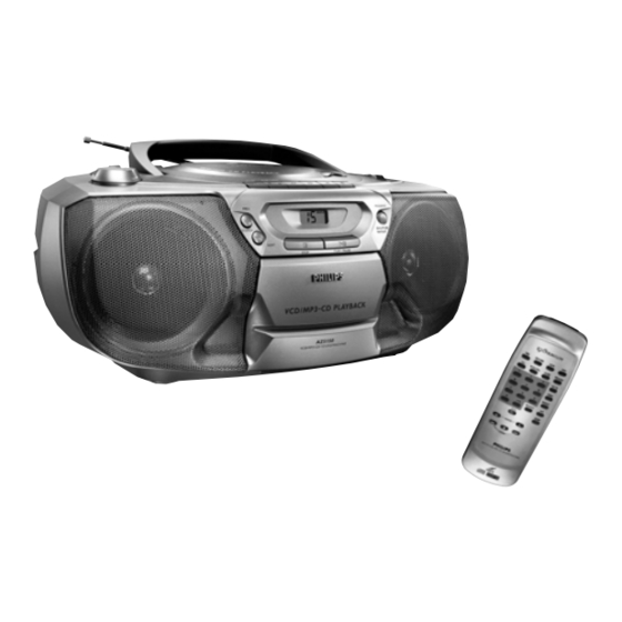
VCD MP3 CD Soundmachine
TABLE OF CONTENTS
Technical Specification & Service tools ...........................2 - 1
Service Measurement......................................................2 - 2
Connections and controls.....................................3 - 1 to 3- 2
Instructions for Use .............................................3 - 3 to 3 - 8
Disassembly Diagram......................................................4 - 1
Pin-description of ICs ..........................................4 - 2 to 4 - 5
Block Diagram .................................................................5 - 1
Wiring Diagram ................................................................6 - 1
Circuit Diagram........................................................7 - 1
Layout Diagram .......................................................7 - 2
Tuner Adjustment ....................................................7 - 2
Circuit Diagram .......................................................8 - 1
Layout Diagram ......................................................8 - 2
©
Copyright 2001 Philips Consumer Electronics B.V. Eindhoven, The Netherlands
All rights reserved. No part of this publication may be reproduced, stored in a retrieval
system or transmitted, in any form or by any means, electronic, mechanical, photocopying,
or otherwise without the prior permission of Philips.
Published by LX 0234 Service Audio
Printed in The Netherlands
Subject to modification
Circuit Diagram........................................................9 - 1
Layout Diagram .......................................................9 - 2
Circuit Diagram......................................................10 - 1
Layout Diagram
Copper side view................................................10 - 2
Component side view .........................................10 - 3
Exploded Views Diagram
Cabinet ..............................................................11 - 1
Tape Deck .........................................................11 - 2
Mechanical Partslist.......................................................11 - 2
Electrical Partslist ............................................12 - 1 to 12 - 2
AZ 5150
all versions
VIDEO CD
CLASS 1
LASER PRODUCT
© 3140 785 32170
Advertisement
Table of Contents

Subscribe to Our Youtube Channel
Related Manuals for Philips Expanium AZ 5150


Summary of Contents for Philips Expanium AZ 5150
-
Page 1: Table Of Contents
LASER PRODUCT © Copyright 2001 Philips Consumer Electronics B.V. Eindhoven, The Netherlands All rights reserved. No part of this publication may be reproduced, stored in a retrieval system or transmitted, in any form or by any means, electronic, mechanical, photocopying, or otherwise without the prior permission of Philips. -
Page 2: Handling Chip Components
1 - 1 HANDLING CHIP COMPONENTS © ñ WARNING WAARSCHUWING All ICs and many other semiconductors are susceptible to Alle IC´s en vele andere halfgeleiders zijn gevoelig voor electrostatic discharges (ESD). Careless handling during electrostatische ontladingen (ESD). repair can reduce life drastically. Onzorgvuldig behandelen tijdens reparatie kan de levensduur When repairing, make sure that you are connected with the drastisch doen vermindern. -
Page 3: Technical Specifications
2 - 1 TECHNICAL SPECIFICATIONS GENERAL TUNER - MW SECTION Tuning range : 520 - 1630 kHz Mains voltage -/01 120/230 V IF frequency : 455 kHz ± 3 kHz Mains frequency -/01 : 50 / 60 Hz Sensitivity : < 4000 µV/m at 26dB S/N Battery mains : 9 V (R14 x 6) Selectivity... -
Page 4: Service Measurement
2 - 2 SERVICE MEASUREMENT Bandpass Tuner SW LF Voltmeter 250Hz-15kHz Aerial replacement e.g. PM2534 e.g. 7122 707 48001 RF Generator Capacitor e.g. PM5326 S/N and distortion meter e.g. Sound Technology ST1700B To avoid atmospheric interference all AM-measurements have to be carried out in a Faraday«s cage. Use a bandpass filter (or at least a high pass filter with 250Hz) to eliminate hum (50Hz, 100Hz). -
Page 5: Connections And Controls
3 - 1 CONNECTIONS AND CONTROLS English... - Page 6 3 - 2 CONNECTIONS AND CONTROLS English English...
-
Page 7: Instructions For Use
3 - 3 INSTRUCTIONS FOR USE English English... - Page 8 3 - 4 INSTRUCTIONS FOR USE English English...
- Page 9 3 - 5 INSTRUCTIONS FOR USE English . .. English...
- Page 10 3 - 6 INSTRUCTIONS FOR USE English English...
- Page 11 3 - 7 INSTRUCTIONS FOR USE English English...
- Page 12 3 - 8 INSTRUCTIONS FOR USE English English...
-
Page 13: Disassembly Diagram
4 - 1 4 - 1 DISASSEMBLY DIAGRAM A. REMOVE BACK CABINET ASSEMBLY - REMOVE SCREWS A1(3x35) 3PCS - REMOVE SCREWS A2(3x20) 2PCS - REMOVE SCREWS A3(3x12) 2PCS - REMOVE BACK CABINET B.REMOVE HANDLE C REMOVE TOP CABINET ASSEMBLY - PRESS DOWN THE STOPER AND - REMOVE SCREWS C4(3x15) 2PCS PULL HTE HANDLE OUT - REMOVE SCREWS C5(3x10) 1PC... -
Page 14: Pin-Description Of Ics
4 - 2 4 - 2 ABBREVIATIONS AND PIN-DESCRIPTION OF ICS ABBREVIATIONS AND PIN-DESCRIPTION OF ICS SERVO PROCESSOR SAA7324H SERVO PROCESSOR SAA7324H SYMBOL DESCRIPTION SYMBOL DESCRIPTION HFREF comparator common mode input microcontroller interface R/W and load control line input (4-wire bus mode) HFIN comparator signal input SILD... - Page 15 4 - 3 4 - 3 BLOCK DIAGRAM OF INTEGRATED CIRCUIT BLOCK DIAGRAM OF INTEGRATED CIRCUIT SERVO PROCESSOR SAA7324 VIDEO DECODER LS187C SSA2 DDA2 SSD2 D1 D2 D3 D4 SSA1 DDA1 SSD1 SSD3 DDD1(P) DDD2(C) PRE- CONTROL PROCESSING FUNCTION OUTPUT STAGES EMI_A_20 CBCR_OUT_3...
- Page 16 4 - 4 4 - 4 BLOCK DIAGRAM OF INTEGRATED CIRCUIT PINS DESCRIPTION OF INTEGRATED CIRCUIT CS8552 CS8552 Name Description CLKI Pixel clock, 27MHz, twice the Y sample rate VSYNC Vertical sync, output in master mode or input in slave mode, is synchronized by CLK.
- Page 17 4 - 5 4 - 5 BLOCK DIAGRAM OF INTEGRATED CIRCUIT IS41C16256 IS41C16256 LCAS I/O0 I/O15 CONTROL CONTROL CLOCK I/O1 I/O14 LOGICS LOGIC UCAS GENERATOR I/O2 I/O13 I/O3 I/O12 I/O4 I/O11 I/O5 I/O10 DATA I/O BUS I/O6 I/O9 CLOCK I/O7 I/O8 GENERATOR COLUMN DECODERS...
-
Page 18: Block Diagram
5 - 1 5 - 1 BLOCK DIAGRAM TUNER ATM3 TUNER +A(CD) +A(ON) UTC2025 ROTARY POWER AMP VOLUME AUDIO OUT L VCD MODULE AUDIO OUT R 8 Ohm, 6W x 2 VIDEO OUT MOTOR TAPE HEADPHONE 32-OHM TAPE MODULE +MOTOR +5V6 TUNER TAPE... -
Page 19: Wiring Diagram
6 - 1 6 - 1 WIRING DIAGRAM... -
Page 20: Tuner Board Circuit Diagram
7 - 1 7 - 1 TUNER BOARD - CIRCUIT DIAGRAM... -
Page 21: Layout Diagram
7 - 2 7 - 2 TUNER BOARD - LAYOUT DIAGRAM TUNER ADJUSTMENT TABLE ( ATM3 FM/AM - versions with AM-frame aerial ) 1102 B 1 2106 A 2 2113 B 4 2119 B 4 3101 A 4 3109 B 4 5104 A 3 5108 B 4 9108 B 2... -
Page 22: Main Board Circuit Diagram
8 - 1 8 - 1 MAIN BOARD - CIRCUIT DIAGRAM... -
Page 23: Layout Diagram
8 - 2 8 - 2 MAIN BOARD - LAYOUT DIAGRAM RECTIFIER BOARD - LAYOUT DIAGRAM... -
Page 24: Cassette Board Circuit Diagram
9 - 1 9 - 1 CASSETTE BOARD - CIRCUIT DIAGRAM... -
Page 25: Layout Diagram
9 - 2 9 - 2 CASSETTE BOARD - LAYOUT DIAGRAM CASSETTE BOARD - ADJUSTMENT Adjustment Cassette SK ..Deck 1 Measure Read Adjust Adjust with Loose Azimuth 6.3 kHz Tape Play H/P Jack mV meter screw of max. R/P head 3 kHz Wow and Motor... -
Page 26: Vcd Board Circuit Diagram
10 - 1 10 - 1 VCD BOARD - CIRCUIT DIAGRAM... -
Page 27: Copper Side View
10 - 2 10 - 2 VCD BOARD - LAYOUT DIAGRAM COPPER SIDE VIEW... -
Page 28: Component Side View
10 - 3 10 - 3 VCD BOARD - LAYOUT DIAGRAM COMPONENT SIDE VIEW... -
Page 29: Cabinet
11 - 1 11 - 1 EXPLODED VIEW DIAGRAM - CABINET SCREW LIST : C M2 x 3 C M2 x 5 C 2 x 8 C M2.6 x 5 C 2.6 x 8 C M3 x 8 (2x) C 3 x 8 C 3 x1 0 C 3 x 12 (2x) -
Page 30: Tape Deck
11 - 2 11 - 2 MECHANICAL PARTSLIST - CABINET EXPLODED VIEW DIAGRAM - TAPE DECK 9965 000 14246 CASSETTE DOOR 4822 528 11359 DIAL DRUM 9965 000 14247 FRONT CONTROL PANEL 9965 000 14233 TUNING KNOB 9965 000 03342 CASSETTE DOOR SPRING 9965 000 14250 REAR CABINET... -
Page 31: Electrical Partslist
12 - 1 ELECTRICAL PARTSLIST - COMBI BOARD - MISCELLANEOUS - - COILS & FILTERS - 4822 276 13443 SWITCH-PUSH 4822 157 11074 100µH 4822 276 13443 SWITCH-PUSH 4822 157 11074 100µH 4822 276 13443 SWITCH-PUSH 4822 157 11074 100µH 4822 276 13443 SWITCH-PUSH 4822 157 11074... - Page 32 12 - 2 ELECTRICAL PARTSLIST - COMBI BOARD - IC & TRANSISTORS - 9965 000 14265 RPM6938-V4 4822 130 62718 JE8050C 9965 000 14275 HMBT8050 4822 130 62718 JE8050C 9965 000 14275 HMBT8050 9965 000 14275 HMBT8050 9965 000 14275 HMBT8050 9965 000 14276 HMBT8550...
Need help?
Do you have a question about the Expanium AZ 5150 and is the answer not in the manual?
Questions and answers