Table of Contents
Advertisement
Quick Links
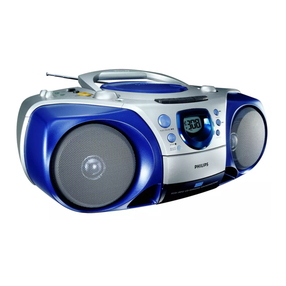
VCD MP3 CD Soundmachine
TABLE OF CONTENTS
Technical Specification & Service tools...........................2 - 1
Service Measurement......................................................2 - 2
Connections and controls........................................3 - 1..3- 2
Instructions for Use ................................................3 - 3..3 - 8
Disassembly Diagram......................................................4 - 1
Pin-description of ICs .............................................4 - 2..4 - 3
Block Diagram .................................................................5 - 1
Wiring Diagram ................................................................6 - 1
Circuit Diagram........................................................7 - 1
Layout Diagram .......................................................7 - 2
©
Copyright 2003 Philips Consumer Electronics B.V. Eindhoven, The Netherlands
All rights reserved. No part of this publication may be reproduced, stored in a retrieval
system or transmitted, in any form or by any means, electronic, mechanical, photocopying,
or otherwise without the prior permission of Philips.
Published by LX 0340Service Audio
Printed in The Netherlands
Subject to modification
VCD Board And LCD Board And Karaoke Board
Circuit Diagram .......................................................8 - 1
Layout Diagram(LCD/Volume Board) .....................8 - 2
Layout Diagram(VCD Board) ..........................8 - 3..8-4
Circuit Diagram........................................................9 - 1
Layout Diagram .......................................................9 - 2
Circuit Diagram......................................................10 - 1
Layout Diagram .....................................................10 - 2
Exploded Views Diagram
Cabinet ..................................................................11 - 1
Tape Deck ............................................................11 - 2
Mechanical Partslist.......................................................11 - 1
Electrical Partslist ...............................................12 - 1..12 - 2
AZ5155
all versions
VIDEO CD
CLASS 1
LASER PRODUCT
© 3140 785 32660
Advertisement
Table of Contents

Related Manuals for Philips AZ5155/01


Summary of Contents for Philips AZ5155/01
-
Page 1: Table Of Contents
LASER PRODUCT © Copyright 2003 Philips Consumer Electronics B.V. Eindhoven, The Netherlands All rights reserved. No part of this publication may be reproduced, stored in a retrieval system or transmitted, in any form or by any means, electronic, mechanical, photocopying, or otherwise without the prior permission of Philips. -
Page 2: Handling Chip Components
1 - 1 HANDLING CHIP COMPONENTS © ñ WARNING WAARSCHUWING All ICs and many other semiconductors are susceptible to Alle IC´s en vele andere halfgeleiders zijn gevoelig voor electrostatic discharges (ESD). Careless handling during electrostatische ontladingen (ESD). repair can reduce life drastically. Onzorgvuldig behandelen tijdens reparatie kan de levensduur When repairing, make sure that you are connected with the drastisch doen vermindern. -
Page 3: Technical Specifications
2 - 1 TECHNICAL SPECIFICATIONS GENERAL TUNER - AM SECTION Tuning range : 526.5 - 1606.5 kHz Mains voltage -/01 : 120/230 V : 465 kHz ± 3 kHz IF frequency Mains frequency -/01 : 50 / 60 Hz Sensitivity : <... -
Page 4: Service Measurement
2 - 2 SERVICE MEASUREMENT Bandpass Tuner SW LF Voltmeter 250Hz-15kHz Aerial replacement e.g. PM2534 e.g. 7122 707 48001 RF Generator Capacitor e.g. PM5326 S/N and distortion meter e.g. Sound Technology ST1700B To avoid atmospheric interference all AM-measurements have to be carried out in a Faraday«s cage. Use a bandpass filter (or at least a high pass filter with 250Hz) to eliminate hum (50Hz, 100Hz). -
Page 5: Connections And Controls
3 - 1 CONNECTIONS AND CONTROLS... - Page 6 3 - 2 CONNECTIONS AND CONTROLS...
-
Page 7: Instructions For Use
3 - 3 INSTRUCTIONS FOR USE... - Page 8 3 - 4 INSTRUCTIONS FOR USE...
- Page 9 3 - 5 INSTRUCTIONS FOR USE...
- Page 10 3 - 6 INSTRUCTIONS FOR USE...
- Page 11 3 - 7 INSTRUCTIONS FOR USE...
- Page 12 3 - 8 INSTRUCTIONS FOR USE...
-
Page 13: Disassembly Diagram
4 - 1 4 - 1 DISASSEMBLY DIAGRAM A.Remove Front Cabinet Assembly B.Remove Top Cabinet C.Remove AF Board D.Remove Tape Deck E.Remove Front Board F. Remove LCD Panel G.Remove Tuner Board H.Remove Control Board I. Remove Handle... - Page 14 4 - 2 4 - 2 BLOCK DIAGRAM OF INTEGRATED CIRCUIT SPCA711A...
- Page 15 4 - 3 4 - 3 BLOCK DIAGRAM OF INTEGRATED CIRCUIT MM1469AH SPCA718A...
-
Page 16: Block Diagram
5 - 1 5 - 1 BLOCK DIAGRAM... -
Page 17: Wiring Diagram
6 - 1 6 - 1 WIRING DIAGRAM... -
Page 18: Tuner Board Circuit Diagram
7 - 1 7 - 1 TUNER BOARD - CIRCUIT DIAGRAM... - Page 19 7 - 2 7 - 2 TUNER BOARD - LAYOUT DIAGRAM...
- Page 20 8 - 1 8 - 1 VCD BOARD/LCD BOARD/KARAOKE BOARD - CIRCUIR DIAGRAM...
-
Page 21: Layout Diagram
8 - 2 8 - 2 LCD BOARD - LAYOUT DIAGRAM KARAOKE BOARD - LAYOUT DIAGRAM... - Page 22 8 - 3 8 - 3 VCD BOARD - LAYOUT DIAGRAM...
- Page 23 8 - 4 8 - 4 VCD BOARD - LAYOUT DIAGRAM...
-
Page 24: Circuit Diagram
9 - 1 9 - 1 AF BOARD AND CONTROL BOARD - CIRCUIT DIAGRAM... -
Page 25: Af Board
9 - 2 9 - 2 AF BOARD - LAYOUT DIAGAM CONTROL BOARD - LAYOUT DIAGRAM... -
Page 26: Cassette Board Circuit Diagram
10 - 1 10 - 1 CASSETTE BOARD - CIRCUIT DIAGRAM... -
Page 27: Layout Diagram
10 - 2 10 - 2 CASSETTE BOARD - LAYOUT DIAGRAM RECORDER BOARD - LAYOUT DIAGRAM 71 A 1 2729 C 5 3733 B 2 9756 C 3 72 D 5 2730 D 1 3734 D 5 9757 D 3 73 A 5 2731 C 1 3735 D 3... -
Page 28: Cabinet
11 - 1 11 - 1 EXPLODED VIEW DIAGRAM - CABINET (2x) SCREW LIST : C M 2.5 x 6 C P/W 2.5 x 10 T2 x 10 T3 x 8 (2x) T3 x 10 (2x) T3 x 12 T3 x 16 T3 x 20 T3 x 25 (4x) -
Page 29: Tape Deck
11- 2 11 - 2 EXPLODED VIEW DAIGARM - CABINET MECHANICAL PARTSLIST - CABINET 9965 000 20742 CASS LENS 9965 000 20741 DOOR CASS 9965 000 20738 BUTTON SET-PLAY 9965 000 14240 TAPE DECK TK20FX-V682-001 9965 000 20737 CASS KNOB SET 9965 000 20731 SPRING-CASS DOOR 9965 000 20739... - Page 30 11 - 3 11 - 3 EXPLODED VIEW DIAGRAM - TAPE DECK MECHANICAL PARTSLIST - TAPE DECK 4822 403 20244 Roller Arm Assy 4822 358 31323 F. Belt 4822 358 31322 Main Belt 4822 403 71219 Eject Belt 4822 249 10475 R/P Head 4822 249 10531 E.
-
Page 31: Electrical Partslist
12 - 1 ELECTRICAL PARTSLIST - MISCELLANEOUS - - COILS & FILTERS - 1256 9965 000 20763 SLIDE SWITCH 9965 000 20549 10µH CHIP INDUCTOR 1302 ! 9965 000 20760 FUSE 3,15A 250V 9965 000 20549 10µH CHIP INDUCTOR 1503 9965 000 20761 SLIDE SWITCH L301... - Page 32 12 - 2 ELECTRICAL PARTSLIST - IC & TRANSISTORS - 1252 5322 209 61473 LM324M 1258 5322 209 61473 LM324M 1259 5322 209 61473 LM324M 7250 4822 130 41319 2SC1815BL 7251 4822 130 41319 2SC1815BL 7252 4822 130 62718 JE8050C 7258 4822 130 62718 JE8050C...
Need help?
Do you have a question about the AZ5155/01 and is the answer not in the manual?
Questions and answers