Table of Contents
Advertisement
Quick Links
Advertisement
Table of Contents

Related Manuals for Supermicro Supero X7SPT-DF-D525


Summary of Contents for Supermicro Supero X7SPT-DF-D525
- Page 1 X7SPT-DF-D525 Revision 1.0...
- Page 2 This product, including software and docu- mentation, is the property of Supermicro and/or its licensors, and is supplied only under a license. Any use or reproduction of this product is not allowed, except as expressly permitted by the terms of said license.
-
Page 3: About This Manual
Preface Preface About This Manual This manual is written for system integrators, PC technicians and knowledgeable PC users. It provides information for the installation and use of the X7SPT-DF-D525 motherboard. This product is intended to be profession- ally installed and serviced by a technician. About This Motherboard The X7SPT-DF-D525 motherboard is a uni-processor twin motherboard. -
Page 4: Conventions Used In The Manual
X7SPT-DF-D525 User’s Manual Conventions Used in the Manual: Special attention should be given to the following symbols for proper installation and to prevent damage done to the components or injury to yourself: Danger/Caution: Instructions to be strictly followed to prevent catastrophic system failure or to avoid bodily injury Warning: Critical information to prevent damage to the components or data loss. -
Page 5: Contacting Supermicro
Super Micro Computer, Inc. 980 Rock Ave. San Jose, CA 95131 U.S.A. Tel: +1 (408) 503-8000 Fax: +1 (408) 503-8008 Email: marketing@supermicro.com (General Information) support@supermicro.com (Technical Support) Web Site: www.supermicro.com Europe Address: Super Micro Computer B.V. Het Sterrenbeeld 28, 5215 ML... -
Page 6: Table Of Contents
Preface About This Manual ......................iii About This Motherboard ....................iii Manual Organization ..................... iii Conventions Used in the Manual: .................iv Contacting Supermicro ....................v Chapter 1 Introduction Overview ......................1-1 Checklist ......................1-1 X7SPT-DF-D525 Image .............. 1-2 Motherboard Layout ..................1-3 Quick Reference ..................... - Page 7 Table of Contents Installation Instructions ..................2-3 System Memory ....................2-4 How to Install SO DIMMs ................2-4 Memory Support ....................2-4 The SO DIMM Socket ..................2-5 Back Panel I/O Ports & Switches ..............2-6 Back Panel Connectors and I/O Ports ............2-6 Universal Serial Bus (USB) ................
- Page 8 X7SPT-DF-D525 User’s Manual Memory Errors ....................3-2 Losing the System’s Setup Configuration ............3-2 Technical Support Procedures ................ 3-2 Frequently Asked Questions ................3-3 Returning Merchandise for Service..............3-5 Chapter 4 BIOS Introduction ...................... 4-1 Starting BIOS Setup Utility ................4-1 How To Change the Configuration Data ............
- Page 9 Table of Contents DRAM RAS# to CAS# Delay ..............4-7 DRAM RAS# Precharge ................4-7 DRAM RAS# Activate to Precharge ............4-7 Internal Graphics Mode Select ..............4-7 Active State Power Management ............... 4-7 USB Functions ................... 4-7 Legacy USB Support (available if USB Functions above is Enabled)..4-7 USB Controller ...................
- Page 10 X7SPT-DF-D525 User’s Manual AMI OEMB Table ..................4-15 ACPI APIC Support .................. 4-16 APIC ACPI SCI IRQ ................. 4-16 Headless Mode ..................4-16 ACPI Version Features ................4-16 IPMI Configuration ..................4-16 IPMI Firmware Revision ................4-16 Status of BMC ..................4-16 IPMI Function ...................
- Page 11 Table of Contents Appendix A POST Error Beep Codes Recoverable POST Error Beep Codes ..............A-1 Appendix B Software Installation Instructions Installing Drivers ....................B-1 Configuring Supero Doctor III .................B-2...
- Page 12 X7SPT-DF-D525 User’s Manual Notes...
-
Page 13: Chapter 1 Introduction
Checklist Congratulations on purchasing your computer motherboard from an acknowledged leader in the industry. Supermicro boards are designed with the utmost attention to detail to provide you with the highest standards in quality and performance. Please check with the system’s manual that all the parts have been included. If anything... -
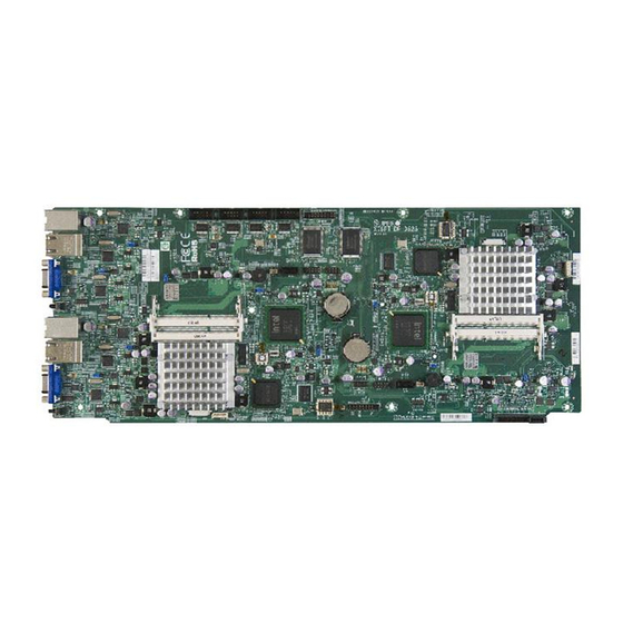
Page 14: X7Spt-Df-D525 Image
X7SPT-DF-D525 User’s Manual X7SPT-DF-D525 Image Note: All graphics shown in this manual were based upon the latest PCB Revision available at the time of publishing of the manual. The motherboard you've received may or may not look exactly the same as the graphics shown in this manual. -
Page 15: Motherboard Layout
Chapter 1: Introduction Motherboard Layout JKPL2 JCOM2 JKDIMM2 JKDIMM1 JCOM1 JKCOM2 JKPB BKT1 LKE1 Important Notes JDIMM1 JDIMM2 • Jumpers not indicated are for testing only. • See Chapter 2 for detailed information on jumpers, I/O ports and JF1 front panel connections. -
Page 16: Quick Reference
X7SPT-DF-D525 User’s Manual Quick Reference JKPL2 Node 2 JCOM2 JKDIMM2 JKDIMM1 JCOM1 JKCOM2 JKPB BKT1 LKE1 JDIMM1 JDIMM2 Node 1 JSMB1... -
Page 17: Ports And Connectors
Chapter 1: Introduction Ports and Connectors *NOTE: All jumpers, connectors, LEDs with "K" in the name are for Node 2. The rest are for Node 1 or shared between the two. Number Connectors* Description JKVGA1, JVGA1 Video/Graphics Connector JKLAN1/JKLAN2, RJ45 Connector for LAN1 and LAN2 JLAN1/JLAN2 5,10 JK666, J666 (top) -
Page 18: Jumper Descriptions
X7SPT-DF-D525 User’s Manual Jumper Descriptions Number Jumper* Description Default Setting SKW1,SW1 Unit ID Switch Open 11, 50 JPL2, JKPL2 LAN2 Enable/Disable Pins 1-2 (Enabled) 12, 49 JPL1, JKPL1 LAN1 Enable/Disable Pins 1-2 (Enabled) Pins 1-2 (Enabled) 26, 44 JPB,JKPB BMC Enable/Disable Pins 2-3 (Disabled) JKWD1, Pins 1-2 (Default) -
Page 19: Motherboard Features
Chapter 1: Introduction Motherboard Features Special Features Twin motherboard with two nodes in one board Processor (Each Node) Single Integrated Dual-Core Intel® ATOM™ D525 processor, 1.8 GHz, 13 Watts, 2 x 512KB L2 cache Memory (Each Node) • Supports up to 4GB of unbuffered 800MHz Non-ECC DDR3 SODIMMs in 2 sockets (1.5V, 512MB, 1GB, 2GB) Chipset (Each Node) •... - Page 20 • USB 2.0 ports & headers (USB1~USB6): Two ports on the back panel • One 20-pin TPM Header • Optimized for the Supermicro 2U chassis. • 12VDC Power through Hot-Plug slot • OEM Options Two Fast 16550-compatible UART COM Ports (internal headers)
-
Page 21: X7Spt-Df-D525 Series Block Diagram
Chapter 1: Introduction X7SPT-DF-D525 BLOCK DIAGRAM 12V DC PINEVIEW-D DDR3 800 hot plug connector D525 FAN PWM control SATA Port 4 SATA Port 3 CK505 CLK Generator SATA GEN2 SATA Port 2 SATA Port 1 GbE(LAN2) Header x2 Intel 82574L USB 2.0 x6 PCI-E x1 ICH9R... -
Page 22: Chipset Overview
X7SPT-DF-D525 User’s Manual Chipset Overview I/O Controller Hub: ICH9R The I/O Controller ICH9R provides the data buffering and interface arbitration re- quired for the system to operate efficiently. It also provides the bandwidth needed for the system to maintain its peak performance. The Direct Media Interface (DMI) provides the connection between the MCH and the ICH9R. -
Page 23: Pc Health Monitoring
Chapter 1: Introduction PC Health Monitoring This section describes the PC health monitoring features of the X7SPT-DF-D525. The motherboard has an onboard System Hardware Monitor chip that supports PC health monitoring. Recovery from AC Power Loss BIOS provides a setting for you to determine how the system will respond when AC power is lost and then restored to the system. -
Page 24: 1-4 Power Configuration Settings
X7SPT-DF-D525 User’s Manual 1-4 Power Configuration Settings This section describes features of your motherboard that deal with power and power settings. Slow Blinking LED for Suspend-State Indicator When the CPU goes into a suspend state, the chassis power LED will start blinking to indicate that the CPU is in suspend mode. -
Page 25: Super I/O
IPMI 2.0 support. This particular chip is installed on the X7SPT-DF-D525 motherboard model. Note: Please refer to the Embedded IPMI User's Guide posted on our website at http://www.supermicro.com/support/manuals/. You may also find information about IPMI by visiting Intel's website at http://www.intel. com/design/servers/ipmi/... -
Page 26: Node Hot-Swapping
X7SPT-DF-D525 User’s Manual Node Hot-Swapping The X7SPT-DF-D525 supports cable-free node hot-swapping when installed in a Supermicro 2U Twin Server chassis together with the cable-free hot-swap adapter (both sold separately). Node hot-swapping enables the user to replace a mother- board in a multi-node server without powering down the entire system. However,... -
Page 27: Chapter 2 Installation
Chapter 2: Installation Chapter 2 Installation Static-Sensitive Devices Electrostatic-Discharge (ESD) can damage electronic com ponents. To pre- vent damage to your system board, it is important to handle it very carefully. The following measures are generally sufficient to protect your equipment from ESD. -
Page 28: Tools Needed
X7SPT-DF-D525 User’s Manual Motherboard Installation All motherboards have standard mounting holes to fit different types of chassis. Make sure that the locations of all the mounting holes for both motherboard and chassis match. Although a chassis may have both plastic and metal mounting fas- teners, metal ones are highly recommended because they ground the motherboard to the chassis. -
Page 29: Installation Instructions
Chapter 2: Installation Caution: To avoid damaging the motherboard and its components, please do not use a force greater than 8 lb/inch on each mounting screw during motherboard installation. Installation Instructions Locate the mounting holes on the motherboard. Refer to the layout on the previous page for mounting hole locations. -
Page 30: System Memory
CAUTION Exercise extreme care when installing or removing DIMM modules to prevent any possible damage. Note: Check the Supermicro website for a list of memory modules that have been validated with the X7SPT-DF-D525 motherboard. How to Install SO DIMMs Insert the desired number of SO DIMMs into the memory slots, starting with DIMM1, then DIMM2. -
Page 31: The So Dimm Socket
Chapter 2: Installation The SO DIMM Socket Align Position the SO DIMM module's bottom key so it aligns with the receptive point on the slot. Insert the SO DIMM module vertically at about a 45 degree Press down until the module angle. -
Page 32: Back Panel I/O Ports & Switches
X7SPT-DF-D525 User’s Manual Back Panel I/O Ports & Switches The I/O ports are color coded in conformance with the PC 99 specification. See the figure below for the colors and locations of the various I/O ports. Back Panel Connectors and I/O Ports JKCOM1 J666 JKTPM... -
Page 33: Universal Serial Bus (Usb)
Chapter 2: Installation Universal Serial Bus (USB) Back Panel USB 0/1, Pin Definitions For each node: 2 Universal Serial Pin# Definition Pin# Definition Bus ports (USB0/1) are located on the I/O backpanel. Additionally, two USB_PN USB_PN USB headers (USB 2/3, 4/5) are also USB_PP USB_PP located on the motherboard to provide... -
Page 34: Lan Ports / Ipmi
X7SPT-DF-D525 User’s Manual LAN Ports / IPMI RJ45/LAN Pin Definitions For each node: There are LAN ports located Pin # Definition Pin # Definition on the I/O back panel. These ports accept TX_D1+ BI_D3- RJ45 type cables. There are two Ethernet TX_D1- RX_D2- ports (LAN1 &... -
Page 35: Vga Connector
Chapter 2: Installation VGA Connector VGA Port/Connector Pin Definitions For each node: A VGA connector is Pin # Definition Pin # Definition located next to the LAN Ports on the Red Video +5V DC I/O back panel. This connector is used Green Video Ground (Vsync, DDC) to provide video display. -
Page 36: Rear Uid (Unit Id) Switch
X7SPT-DF-D525 User’s Manual Rear UID (Unit ID) Switch The Rear UID Switch is used together with the Front Panel UID LED and Rear UID LED (located next to the UID Switch). The Rear UID Switch makes it easier to identify or 'mark' the unit by turning on both the blue UID Switch (Node 1) UID LED on the back panel and the... -
Page 37: Header Connections
Chapter 2: Installation Header Connections This section provides brief descriptions and pin-out definitions for onboard header connectors. Be sure to use the correct cable for each header or connector. Serial Ports (JKCOM/JCOM) - OEM Serial Ports-COM1/COM2/COM3/COM4 Option Pin Definitions Pin # Definition Pin # Definition... -
Page 38: Universal Serial Bus (Jusb/Jkusb)
X7SPT-DF-D525 User’s Manual Universal Serial Bus (JUSB/JKUSB) Front Panel USB 2/3, USB 4/5 Pin Definitions For each node, there are two USB head- Pin # Definition Pin # Definition ers located on the motherboard to provide front chassis access. (Cables are not USB_PN USB_PN included). -
Page 39: Front Panel Accessible Add-On Card Header (Jf2)
Chapter 2: Installation Front Panel Accessible Add-on Card Header (JF2) JF2 Add-on card header provides front access to the power supply, Serial ATA and Front Panel Control connections for the motherboard. Plug an Add-On card into this header to use the functions indicated above. This header is designed specifically for this motherboard. -
Page 40: Onboard Speaker (Jksp1/Sp1)
X7SPT-DF-D525 User’s Manual Onboard Speaker (JKSP1/SP1) Trusted Platform Module Header Pin Definitions An onboard speaker or buzzer is pro- Pin # Definition Pin # Definition vided for each node. This device pro- LCLK vides audible status messages for the LFRAME No Pin motherboard. -
Page 41: Smb (Jsmb1/Jksmb1)
Chapter 2: Installation SMB (JSMB1/JKSMB1) SMB Header Pin Definition A System Management Bus (SMB) Pin# Definition header is located at JSMB1 for Node 1 Data and JKSMB1 for Node 2. Connect the Ground appropriate cable here to use the SMB Clock C connection on your system. -
Page 42: Jumper Settings
X7SPT-DF-D525 User’s Manual Jumper Settings Explanation of Jumpers To modify the operation of the motherboard, jumpers can be used to choose between optional settings. Jumpers create shorts between two pins to change the function of the connector. Pin 1 is identified with a square solder pad on the printed circuit board. -
Page 43: Lan Port Enable/Disable (Jpl/Jkpl)
Chapter 2: Installation LAN Port Enable/Disable (JPL/JKPL) LAN Enable Jumper Settings The JPL jumper is used to disable/enable Pin# Definition the LAN ports on the motherboard. See the table on the right for jumper settings. Enabled (default) The default setting is enabled. Disabled BMC Enable/Disable (JPB/JKPB) The JPB jumper is used to enable or... -
Page 44: Cmos Clear (Jbt1/Jkbt1)
X7SPT-DF-D525 User’s Manual CMOS Clear (JBT1/JKBT1) JBT1 is used to clear CMOS. Instead JBT1: COMS CLEAR of pins, this "jumper" consists of contact JPC3 I-SA T-SGPIO2 T-SGPIO1 JVGA1 pads to prevent accidental clearing of JI2C2 ON:ENABLE OFF:DISABLE the CMOS. To clear the CMOS, use a metal object such as a small screwdriver to touch both pads at the same time to LAN1... -
Page 45: Onboard Indicators
Chapter 2: Installation Onboard Indicators GLAN Link/Speed LED Indicator LAN Port LEDs LED Color Definition Four total LAN ports are located on the I/O No Connection or 10 Mbps Backpanel. Each Ethernet LAN port has Green (On) 100 Mbps Amber (On) 1 Gbps two LEDs. -
Page 46: Unit Id Leds (Le2/Lke2)
X7SPT-DF-D525 User’s Manual Unit ID LEDs (LE2/LKE2) There are two unit ID LEDs on the motherboard, one for each node. Each Unit ID LED is associated with a Unit ID switch. The Unit ID Switch activates the Unit ID LED next to it, and the corresponding Unit ID LED on the front panel of the chassis (if so equipped). -
Page 47: Sata Led (Dkp3/Dp3)
Chapter 2: Installation SATA LED (DKP3/DP3) There are two SATA LEDs on the motherboard, one for each node. When this LED is blinking, it indicates activity on the system's SATA port(s). BMC Heartbeat LED (DKP1/DP1) There are two BMC Heartbeat LEDs on the motherboard, one for each node. When this LED is blinking, it indicates that the Baseboard Management Controller (BMC) is activated. -
Page 48: Serial Ata Ports
X7SPT-DF-D525 User’s Manual Serial ATA Ports SATA Connectors SATA Connectors Pin Definitions There are 4 SATA ports supported on Pin# Signal each node. IKSATA1/ISATA1 are located Ground on the motherboard, while the rest are SATA_TXP supported through the hot-plug using an SATA_TXN adapter card (see JF2, 2-13). -
Page 49: Troubleshooting Procedures
Chapter 3: Troubleshooting Chapter 3 Troubleshooting Troubleshooting Procedures Use the following procedures to troubleshoot your system. If you have followed all of the procedures below and still need assistance, refer to the ‘Technical Support Procedures’ and/or ‘Returning Merchandise for Service’ section(s) in this chapter. Always disconnect the AC power cord before adding, changing or installing any hardware components. -
Page 50: X7Spt-Df-D525 User's Manual
Before contacting Technical Support, please make sure that you have followed all the steps listed below. Also, Note that as a motherboard manufacturer, Supermicro does not sell directly to end users, so it is best to first check with your distributor or reseller for troubleshooting services. -
Page 51: Frequently Asked Questions
3. If you've followed the instructions above to troubleshoot your system, and still cannot resolve the problem, then contact Supermicro's technical support and provide them with the following information: • Motherboard model and PCB revision number •... - Page 52 Note: The SPI BIOS chip installed on this motherboard is not removable. To repair or replace a damaged BIOS chip, please send your motherboard to RMA at Supermicro for service. Question: What's on the CD that came with my motherboard? Answer: The supplied compact disc has quite a few drivers and programs that will greatly enhance your system.
-
Page 53: Returning Merchandise For Service
Chapter 3: Troubleshooting Returning Merchandise for Service A receipt or copy of your invoice marked with the date of purchase is required before any warranty service will be rendered. You can obtain service by calling your vendor for a Returned Merchandise Authorization (RMA) number. When returning to the manufacturer, the RMA number should be prominently displayed on the outside of the shipping carton, and mailed prepaid or hand-carried. - Page 54 X7SPT-DF-D525 User's Manual Notes...
-
Page 55: Chapter 4 Bios
When an option is selected in the left frame, it is highlighted in white. Often a text message will accompany it. (Note: the AMI BIOS has default text messages built in. Supermicro retains the option to include, omit, or change any of these text messages.) The AMI BIOS Setup Utility uses a key-based navigation system called "hot keys". -
Page 56: How To Start The Setup Utility
Warning! Do not upgrade the BIOS unless your system has a BIOS-related issue. Flashing the wrong BIOS can cause irreparable damage to the system. In no event shall Supermicro be liable for direct, indirect, special, incidental, or consequential damages arising from a BIOS update. If you have to update the BIOS, do not shut down or reset the system while the BIOS is updating. -
Page 57: System Overview: The Following Bios Information Will Be Displayed
<Tab> key or the arrow keys to move between fields. The date must be entered in Day MM/DD/YY format. The time is entered in HH:MM:SS format. (Note: The time is in the 24-hour format. For example, 5:30 P.M. appears as 17:30:00.) Supermicro X7SPA/X7SPE/X7SPT Series Version Build Date... -
Page 58: 4-3 Advanced Setup Configurations
X7SPT-DF-D525 User's Manual 4-3 Advanced Setup Configurations Use the arrow keys to select Boot Setup and hit <Enter> to access the submenu items: BOOT Feature Quick Boot If Enabled, this option will skip certain tests during POST to reduce the time needed for system boot. -
Page 59: Bootup Num-Lock
Chapter 4: AMI BIOS Bootup Num-Lock This feature selects the Power-on state for Numlock key. The options are Off and On. Wait For 'F1' If Error This forces the system to wait until the 'F1' key is pressed if an error occurs. The options are Disabled and Enabled. -
Page 60: Cpu Configuration
X7SPT-DF-D525 User's Manual CPU Configuration Warning : Take Caution when changing the Advanced settings. An incorrect value, a very high DRAM frequency or incorrect DRAM timing may cause system to become unstable. When this occurs, revert to the default setting. Clock Spread Spectrum Select Enable to use the feature of Clock Spectrum, which will allow the BIOS to monitor and attempt to reduce the level of Electromagnetic Interference caused by... -
Page 61: Dram Cas# Latency
Chapter 4: AMI BIOS DRAM CAS# Latency The options are [3], [4], [5], and [6] DRAM RAS# to CAS# Delay The options are 3 DRAM Clocks, 4 DRAM Clocks, 5 DRAM Clocks, and 6 DRAM Clocks. DRAM RAS# Precharge The options are 3 DRAM Clocks, 4 DRAM Clocks, 5 DRAM Clocks, and 6 DRAM Clocks. -
Page 62: Ide/Sata Configuration
X7SPT-DF-D525 User's Manual IDE/SATA Configuration When this submenu is selected, the AMI BIOS automatically detects the presence of the IDE Devices and displays the following items: SATA#1 Configuration If Compatible is selected, it sets SATA#1 to legacy compatibility mode, while se- lecting Enhanced sets SATA#1 to native SATA mode. - Page 63 Chapter 4: AMI BIOS Block (Multi-Sector Transfer) Block Mode boosts the IDE drive performance by increasing the amount of data transferred. Only 512 bytes of data can be transferred per interrupt if Block Mode is not used. Block Mode allows transfers of up to 64 KB per interrupt. Select Disabled to allow data to be transferred from and to the device one sector at a time.
-
Page 64: Pci/Pnp Configuration
X7SPT-DF-D525 User's Manual Select MWDMA2 to allow the BIOS to use Multi-Word DMA mode 2. It has a data transfer rate of 16.6 MBs. Select UDMA0 to allow the BIOS to use Ultra DMA mode 0. It has a data transfer rate of 16.6 MBs. -
Page 65: Pci Latency Timer
Chapter 4: AMI BIOS PCI Latency Timer This feature sets the latency Timer of each PCI device installed on a PCI bus. Select 64 to set the PCI latency to 64 PCI clock cycles. The options are 32, 64, 96, 128, 160, 192, 224 and 248. -
Page 66: Hardware Health Configuration
X7SPT-DF-D525 User's Manual If Remote Access is set to Enabled, the following items will display: Serial Port Number This feature allows the user decide which serial port to be used for Console Redirection. The options are COM 1, COM 2 and COM 3. Serial Port Mode This feature allows the user to set the serial port mode for Console Redirection. -
Page 67: Cpu Temperature
Chapter 4: AMI BIOS Warning: Any temperature that exceeds the CPU threshold temperature predefined by the CPU manufacturer may result in CPU overheat or system instability. When the CPU temperature reaches this predefined threshold, the CPU and system cooling fans will run at full speed. The options are: •... -
Page 68: Fan1/Fan2 Speed
Tolerances’, the installed CPU can now send its ‘Temperature Toler- ance’ to the motherboard resulting in better CPU thermal management. Supermicro has leveraged this feature by assigning a temperature status to certain thermal conditions in the processor (Low, Medium and High). This makes it easier for the user to understand the CPU’s temperature status,... -
Page 69: Cpu Vcore, Avcc, 3.3Vcc, 12V, V_Dimm, 5V, -12V, 3.3Vsb, And Vbat
Chapter 4: AMI BIOS system cooling. The Performance setting is recommended for high-power-consum- ing and high-density systems. Select Balanced for the onboard fans to run at 50% of the Initial PWM Cycle in order to balance the needs between system cooling and power saving. -
Page 70: Acpi Apic Support
X7SPT-DF-D525 User's Manual ACPI APIC Support Select Enabled to include the ACPI APIC Table Pointer in the RSDT (Root System Description Table) pointer list. The options are Enabled and Disabled. APIC ACPI SCI IRQ When this item is set to Enabled, APIC ACPI SCI IRQ is supported by the system. The options are Enabled and Disabled. -
Page 71: Clear Bmc System Event Log
Chapter 4: AMI BIOS Clear BMC System Event Log This feature is used to clear the System Event Log. Caution: Any cleared information is unrecoverable. Make absolutely sure you no longer need any data stored in the log before clearing the BMC Event Log. Set LAN Configuration Set this feature to configure the IPMI LAN adapter with a network address. -
Page 72: Bmc Watch Dog Timer Action
X7SPT-DF-D525 User's Manual BMC Watch Dog Timer Action Allows the BMC to reset or power down the system if the operating system hangs or crashes. The options are Disabled, Reset System, Power Down, Power Cycle. BMC WatchDog TimeOut [Min:Sec] This option appears if BMC Watch Dog Timer Action (above) is enabled. This is a timed delay in minutes or seconds, before a system power down or reset after an operating system failure is detected. -
Page 73: Security Settings
Chapter 4: AMI BIOS Security Settings The AMI BIOS provides a Supervisor and a User password. If you use both pass- words, the Supervisor password must be set first. Supervisor Password This item indicates if a supervisor password has been entered for the system. Clear means such a password has not been used and Set means a supervisor password has been entered for the system. -
Page 74: Change User Password
X7SPT-DF-D525 User's Manual Change User Password Select this feature and press <Enter> to access the submenu , and then type in a new User Password. Clear User Password (Available only if User Password has been set) Password Check Available options are Setup and Always. Boot Sector Virus Protection When Enabled, the AMI BOIS displays a warning when any program (or virus) is- sues a Disk Format command or attempts to write to the boot sector of the hard... -
Page 75: Boot Settings
Chapter 4: AMI BIOS Boot Settings Use this feature to configure Boot Settings: Boot Device Priority This feature allows the user to specify the sequence of priority for the Boot Device. The settings are 1st boot device, 2nd boot device, 3rd boot device, 4th boot device, 5th boot device and Disabled. -
Page 76: Removable Drives
X7SPT-DF-D525 User's Manual Removable Drives This feature allows the user to specify the boot sequence from available Removable Drives. The settings are 1st boot device, 2nd boot device, and Disabled. • 1st Drive • 2nd Drive - [USB: XXXXXXXXX] Retry Boot Devices Select this option to retry booting from the configured boot devices if the systems fail to boot initially. -
Page 77: Discard Changes And Exit
Chapter 4: AMI BIOS figuration parameters can take effect. Select Save Changes and Exit from the Exit menu and press <Enter>. Discard Changes and Exit Select this option to quit the BIOS Setup without making any permanent changes to the system configuration, and reboot the computer. Select Discard Changes and Exit from the Exit menu and press <Enter>. - Page 78 X7SPT-DF-D525 User's Manual Notes 4-24...
-
Page 79: Appendix A Post Error Beep Codes
Appendix A: POST Error Beep Codes Appendix A POST Error Beep Codes This section lists POST (Power On Self Test) error beep codes for the AMI BIOS. POST error beep codes are divided into two categories: recoverable and terminal. This section lists Beep Codes for recoverable POST errors. Recoverable POST Error Beep Codes When a recoverable type of error occurs during POST, BIOS will display a POST code that describes the problem. - Page 80 X7SPT-DF-D525 User's Manual Notes...
-
Page 81: Appendix B Software Installation Instructions
Appendix C: Software Installation Instructions Appendix B Software Installation Instructions B-1 Installing Drivers After you've installed the Windows Operating System, a screen as shown below will appear. You are ready to install software programs and drivers that have not yet been installed. To install these software programs and drivers, click the icons to the right of these items. -
Page 82: Configuring Supero Doctor Iii
X7SPT-DF-D525 User's Manual B-2 Configuring Supero Doctor III The Supero Doctor III program is a Web-base management tool that supports remote management capability. It includes Remote and Local Management tools. The local management is called the SD III Client. The Supero Doctor III program included on the CDROM that came with your motherboard allows you to monitor the environment and operations of your system. - Page 83 Supero Doctor III Interface Display Screen-II (Remote Control) Note: SD III Software Revision 1.0 can be downloaded from our Web site at: ftp://ftp.supermicro.com/utility/Supero_Doctor_III/. You can also download SDIII User's Guide at: http://www.supermicro.com/PRODUCT/ Manuals/SDIII/UserGuide.pdf. For Linux, we will still recommend that you...
- Page 84 X7SPT-DF-D525 User's Manual Notes...
- Page 85 (Disclaimer Continued) The products sold by Supermicro are not intended for and will not be used in life support systems, medical equipment, nuclear facilities or systems, aircraft, aircraft devices, aircraft/emergency communication devices or other critical systems whose failure to perform be reasonably expected to result in significant injury or loss of life or catastrophic property damage.
Need help?
Do you have a question about the Supero X7SPT-DF-D525 and is the answer not in the manual?
Questions and answers