Advertisement
INSTALLATION AND MAINTENANCE
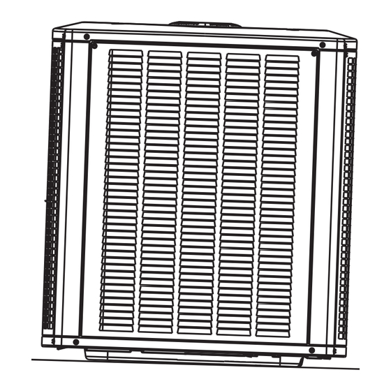
Split System Air Conditioner
The equipment covered in this manual is to be installed by trained and experienced
service and installation technicians. Improper installation, modification, service, or
use can cause electrical shock, fire, explosion, or other conditions which may cause
personal injury, death, or property damage. Use appropriate safety gear including
safety glasses and gloves when installing this equipment.
WARNING
Risk of electrical shock. Disconnect all
remote power supplies before installing or
servicing any portion of the system. Failure
to disconnect power supplies can result in
property damage, personal injury, or death.
WARNING
Installation and servicing of air conditioning
equipment can be hazardous due to internal
refrigerant pressure and live electrical com-
ponents. Only trained and qualified service
personnel should install or service this equip-
ment. Installation and service performed by
unqualified persons can result in property
damage, personal injury, or death.
WARNING
Sharp metal edges can cause injury. When
installing the unit, use care to avoid sharp
edges.
# 48283B006
INSTRUCTIONS
2SCU13 Series
WARNING
Save these instructions for future reference
TABLE OF CONTENTS
INSTALLATION ...................................... 2
START-UP ............................................ 10
OPERATION ........................................ 14
MAINTENANCE ................................... 14
CONNECTION DIAGRAMS ................. 16
Manufactured By
A.A.C.
A Lennox International Inc. Company
421 Monroe Street
Bellevue, OH 44811
*48283B006*
Page 1
Advertisement
Table of Contents

Related Manuals for Lennox 2SCU13 Series


Summary of Contents for Lennox 2SCU13 Series
-
Page 1: Table Of Contents
INSTALLATION AND MAINTENANCE INSTRUCTIONS 2SCU13 Series Split System Air Conditioner WARNING The equipment covered in this manual is to be installed by trained and experienced service and installation technicians. Improper installation, modification, service, or use can cause electrical shock, fire, explosion, or other conditions which may cause personal injury, death, or property damage. -
Page 2: Installation
INSTALLATION Location of Unit Outdoor units operate under a wide range of weather General conditions; therefore, multiple factors must be considered Read this entire instruction manual, as well as the when positioning the unit. The unit must be positioned to instructions supplied in separate equipment, before give adequate clearances for sufficient airflow and servic- ing. -
Page 3: Slab Mounting
1. Install line voltage power supply to unit from a properly Slab Mounting sized disconnect switch. Any excess high voltage field wiring should be trimmed or secured away from the Discharge Air low voltage field wiring. Building Structure 2. Ground unit at unit disconnect switch or to an earth ground. - Page 4 suction riser to maintain minimum velocity at minimum energy or vibration can be expected. Close attention to capacity. Recommended line length is 50' or less. If more line set isolation must be observed. than 50' line set is required, contact Technical Services at (419) 483-4840.
- Page 5 Refrigerant Line Sets: Installing Horizontal Runs To hang line set from joist or rafter, use either metal strapping material Wire Tie or anchored heavy nylon wire ties. (around vapor line only) 8’ Strapping Material Floor Joist or (around vapor line only) Roof Rafter Tape or Wire Tie 8’...
- Page 6 Refrigerant Line Sets: Installing Vertical Runs (new construction shown) IMPORTANT: Refrigerant lines must not contact wall. Outside Wall Vapor Line Liquid Line NOTE: Similar installation practices should be used if line set is to be Wood Block installed on exterior of outside wall. Between Studs Wire Tie Inside Wall...
- Page 7 the expansion valve along with a new teflon seal into the distributor and tighten to 20 – 30 ft. lbs. Use backup Fixed Orifice Data wrench on all wrench flats. Overtightening will crush the teflon seal and may cause a leak. l l i 2.
- Page 8 Ball Type Service Valve Service Valve (Valve Open) Valve Closed Use adjustable wrench. To open, rotate stem counterclockwise 1/4 turn (90°). To close, rotate stem clockwise 1/4 turn (90°). Figure 11 Leak Testing After the line set has been connected to the indoor and outdoor units, the line set connections and indoor unit must be checked for leaks.
- Page 9 2. With both manifold valves closed, connect the cylin- 5. Evacuate the line set and indoor unit to a minimum of 500 der of HCFC-22 refrigerant. Open the valve on the microns or lower. During the early stages of evacuation, it HCFC-22 cylinder (vapor only).
-
Page 10: Start-Up
START-UP If the system is void of refrigerant, clean the system using the procedure described below. 1. Use dry nitrogen to pressurize the system and check CAUTION for leaks. Repair leaks, if possible. If unit is equipped with a crankcase heater, it should be energized 24 hours before unit 2. - Page 11 Charge Using Weigh-In Method (Fixed Orifice/TXV Systems) Subcooling Values for Fixed Orifice or TXV Systems If the system is void of refrigerant, or if the outdoor ambient temperature is cool, first locate and repair any leaks then use the weigh-in method to charge the unit. ±...
- Page 12 Superheat Values for Approach Values for TXV Systems Fixed Orifice Systems (80°DB/67°WB Return Air) F ° F ° F ° Approach value is the liquid line temperature minus the outdoor ambient temperature (±1°F). NOTE: For best results, use the same digital thermometer to check both outdoor ambient and liquid temperatures.
-
Page 13: Normal Operating Pressures
Normal Operating Pressures F ° F ° F ° F ° F ° F ° F ° F ° F ° F ° F ° F ° L – Liquid S – Suction Values provided above are typical pressures. Indoor unit matchup, indoor air quality, and indoor load will cause pressures to vary. -
Page 14: Operation
OPERATION MAINTENANCE Outdoor unit and indoor blower cycle on demand from the WARNING room thermostat. When the thermostat blower switch is moved to the ON position, the indoor blower operates Before performing maintenance operations on continuously. system, turn the electric power to unit OFF at disconnect switch(es). - Page 15 5. Check for correct voltage at unit (with unit operating). 6. Check amp-draw on blower motor. Unit nameplate _________ Actual _________ Start-Up and Performance Checklist Job Name _______________________________ Job No. ________________ Date ______________ Job Location _____________________________ City ___________________ State ______________ Installer _________________________________ City ___________________ State ______________...
-
Page 16: Connection Diagrams
OUTDOOR DUAL CAPACITOR TIMED OFF CONTROL PURPLE TO 24 VAC (IF USED) BLACK POWER SOURCE 20 VA MINIMUM ORANGE NEC CLASS 2 YELLOW BLACK COMPRESSOR COMPRESSOR CONTACTOR CRANKCASE HEATER (IF USED) GROUND 208-230/60/1 GROUND BLACK K1-1 S4 HIGH 208-230/60/1 S24 LOSS YELLOW PRESSURE OF CHARGE... - Page 17 OUTDOOR OUTDOOR FAN CAPACITOR TIMED OFF CONTROL PURPLE TO 24 VAC (IF USED) BLACK POWER SOURCE ORANGE 10 VA MINIMUM NEC CLASS 2 BLACK BLACK COMPRESSOR BLACK T3 T2 T1 COMPRESSOR CONTACTOR CRANKCASE HEATER L3 L2 L1 (IF USED) GROUND 208-230/60/3 GROUND 208-230/60/3...
-
Page 18: Limited Warranty
Limited Warranty August 1, 1997 This warranty gives you specific legal rights and you may have other rights which vary from state/province to state/province. Warrantor: Armstrong Air Conditioning Inc., 421 Monroe St., Bellevue, OH 44811 Armstrong Air Conditioning Inc. products are available under the following names: Air Ease, Armstrong Air, American Aire, Concord Subject to the limitations stated in this warranty, we warrant to the first buyer for use the residential heating, cooling or heat pump unit, when installed, operated and maintained as required by this warranty, to be free of defects in workmanship or material for a period of 5 years (1 year for commercial equipment) from the time of installation.
Need help?
Do you have a question about the 2SCU13 Series and is the answer not in the manual?
Questions and answers