
Related Manuals for Tsurumi Pump TPG-2900H-DX


Summary of Contents for Tsurumi Pump TPG-2900H-DX
- Page 1 OPERATION, SERVICE, AND REPAIR MANUAL FOR TSURUMI TPG-SERIES PORTABLE GENERATORS MODELS TPG-2900H-DX TPG-4300H-DX TPG-6000H-DX TPG-7000H-DXE...
-
Page 2: Limited Warranty
LIMITED WARRANTY TSURUMI MANUFACTURING CO., LTD. (“TSURUMI”) warrants to the original end purchaser during the warranty period, every new TSURUMI generator or product to be free from defects in material and workmanship under normal use and service, when properly installed, used, and maintained (in accor- dance with Tsurumi’s Operation, Service, and Repair Manual) for a period of two years from the date the unit was first installed or twenty six months from the date of shipment by TSURUMI to wholesaler, whichever comes first. -
Page 3: Table Of Contents
Replacement of Engine Muffler ........(Model TPG-2900H-DX) Replacement of Fuel Tank . -
Page 4: Introduction
If you have a problem with your generator that cannot be resolved using the Operation, Repair, and Service Manual, or if you have questions about the operation, service, repair, or maintenance of your generator, contact your local Tsurumi generator dealer. Page 1 TPG-2900H-DX TPG-4300H-DX TPG-6000H-DX TPG-7000H-DXE... -
Page 5: Precautions And Placards
A. PRECAUTIONS AND PLACARDS Pay special attention to precautionary notes preceded by the words WARNING, CAUTION, and NOTE. WARNINGS indicate that there is a strong possibility of personal injury or loss of life if the procedure is not followed, or if cleaning, lubricating, adhesives, and other materials are not used properly. CAUTIONS indicate that there is a possibility of equipment damage if instructions are not followed. -
Page 6: Data Plate
The large label below is located on the front panel of the portable generator. The label pres- ents operational Warnings and Cautions for generator users. -
Page 7: Safety Precautions
B. SAFETY PRECAUTIONS WARNING: IN ORDER TO ASSURE SAFE AND EFFICIENT OPERATION OF THE GENERATOR, OPERA- • TOR’S SHOULD READ AND COMPLY WITH THE FOLLOWING SAFETY PRECAUTIONS. Do not operate the generator near gasoline or gaseous fuels because of the potential dan- •... -
Page 8: Specifications/Key Features
• Automatic Idle Control…reduces fuel consumption, noise, and engine wear (this feature is not • available on Model TPG-2900H-DX). Large, Silent Muffler (with USDA qualified spark arrestor) to significantly reduce noise. The • spark arrestor is designed to screen out hot sparks. -
Page 9: Description And Operation
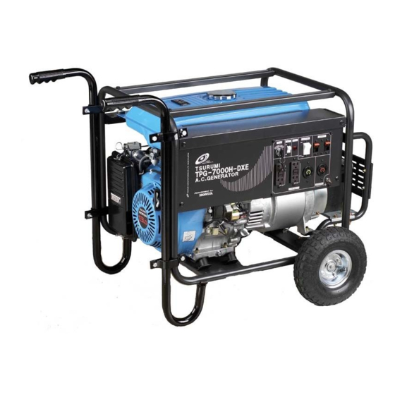
2. DESCRIPTION AND OPERATION A. PHYSICAL DESCRIPTION Description of the Portable Generator The key features of the portable generator are shown in Figure 1. A cutaway view of the generator is provided in Figure 2. Fuel Tank Air Filter Engine... - Page 10 The rear cover supports a ball bearing at the back end of the generator rotor. The rear cover has a removable access plate to provide access to the stator wiring (an access plate is not used on Model TPG-2900H-DX.) The rotor consists of a shaft, a stack of steel laminations, and copper wire windings.
- Page 11 7000-DX is installed in the exhaust port of the muffler. The spark arrestor for Model TPG-2900H-DX is installed in the inlet side of the muffler. The engine has an oil filler plug that is used to check engine oil level. Engine oil is added through the same filler plug port.
-
Page 12: Functional Description
Tsurumi’s Operation, Service, and Repair Manual The engine, starter, and control wiring exits through a hole in the side of the control box. The diode and fuse that are part of the DC circuit are located inside the control box. The generator leads and control wiring are connected inside the control box. - Page 13 Full Power Switch (Dual Voltage Type) (refer to Figure 4) The full power switch provides both 120V and 240V dual voltages at full rated power. The full rated power will be available from one 120V receptacle and one 240V recep- tacle.
- Page 14 Tsurumi’s Operation, Service, and Repair Manual MC 1 MC 2 Figure 5: Full Power Switch Set for Single-Voltage Output Figure 6: Full Power Switch Set for Dual-Voltage Output Table 1: Full Power Switch – Switch Setting Versus Output Available Switch Position 110V or 120V...
-
Page 15: Operating Instructions
3. OPERATING INSTRUCTIONS A. OPERATING CONTROLS The main operating controls for the generator are, with a few exceptions, mounted on the front panel of the generator. The controls consist of an ENGINE switch, an IDLE switch, a FULL POWER switch, a PILOT light, circuit BREAKER(s), a ground (or earth) post, and electrical receptacles. - Page 16 MANUFACTURING CO., LTD. Engine Switch Idle Switch Pilot Light Full Power Switch 14 Amp Circuit Breaker Page 13 AC 120V LEGEND Figure 7: Model TPG-2900H-DX ENGINE STOP MAX20 LEGEND Figure 8: Model TPG-4300H-DX ENGINE PILOT BREAKER STOP 18 Amp Circuit Breaker...
- Page 17 TSURUMI MANUFACTURING CO., LTD. Engine Switch Idle Switch Pilot Light Full Power Switch 30 Amp Circuit Breaker TSURUMI MANUFACTURING CO., LTD. Engine Switch Idle Switch Pilot Light Full Power Switch 5. 30 Amp Circuit Breaker Operating Instructions Tsurumi’s Operation, Service, and Repair Manual ENGINE IDLE MAX20...
-
Page 18: Check The Engine Oil Level
Tsurumi’s Operation, Service, and Repair Manual C. CHECK THE ENGINE OIL LEVEL CAUTION: • Engine oil is a major factor affecting performance and service life. Non-detergent oils and 2-stroke oils are not recommended because they have inadequate lubricating characteristics • Check the oil level with the engine on a level surface and the engine stopped. Use Honda 4-stroke oil, or use an equivalent high detergent, premium quality motor oil cer- tified to meet or exceed U.S. -
Page 19: Check Engine Fuel
Check fuel level at fuel level gauge (refer to Figure 14). If fuel level is low, refill with unleaded automotive gasoline. Fuel tank capacity Operating Instructions Tsurumi’s Operation, Service, and Repair Manual Figure 13: Checking Oil Level TPG-2900H-DX (2.9 gal.) TPG-4300H-DX (4.5 gal.) TPG-6000H-DX (4.5 gal.) TPG-7000H-DXE (4.5 gal.) -
Page 20: Pre-Start Checks
Tsurumi’s Operation, Service, and Repair Manual E. PRE-START CHECKS WARNING: • MAKE SURE YOU REVIEW EACH WARNING IN ORDER TO PREVENT FIRE HAZARD. • KEEP AREA CLEAR OF FLAMMABLES OR OTHER HAZARDOUS MATERIALS. Check the following items before starting the engine. Fuel leakage from fuel hose, etc. -
Page 21: Using The Generator
NOTE: • The choke may not be needed if the engine is warm or the air temperature is high. Move the throttle lever slightly to the left. (MODEL TPG-7000H-DXE ONLY): To start the engine using the electric starter, proceed as follows: Turn key in engine START/STOP switch. - Page 22 Tsurumi’s Operation, Service, and Repair Manual NOTE: • Check the amperage of the receptacles used referring to Table 2, and be sure not to take a current exceeding the specified amperage. • Be sure that the total wattage of all appliances does not exceed the rated output of the generator. WARNING: •...
-
Page 23: Stopping The Generator
Available Receptacles With Full Power Switch On Switch Setting 120V 120V/240V WARNING: • TO TAKE OUT POWER FROM TWIST LOCK RECEPTACLE, INSERT THE PLUG INTO RECEP- TACLE AND TURN CLOCKWISE TO LOCK IT. • BE SURE TO GROUND THE GENERATOR IF THE CONNECTED ELECTRICAL EQUIPMENT IS GROUNDED. -
Page 24: Oil Alert
Tsurumi’s Operation, Service, and Repair Manual OIL ALERT The oil alert detects the fall in oil level in the crankcase and automatically stops the engine when the oil level falls down below the predetermined level. When the engine has stopped automatically, check the oil level. Refill engine oil to the upper level and restart the engine. - Page 25 Applicable Wattage (W) Incandescent Lamp, Heater Fluorescent Lamp, Mercury Lamp Electric Tool Pump, Compressor Operating Instructions Tsurumi’s Operation, Service, and Repair Manual Table 4 Wattage Chart Applicable Wattage (w) TPG-2900H-DX TPG-4300H-DX 60 Hz 60 Hz 2000 3300 1200 1900 1200 1900...
-
Page 26: Maintenance
Tsurumi’s Operation, Service, and Repair Manual 4. MAINTENANCE To maintain the generator in peak operating condition, observe and implement the maintenance and adjustment schedule in Table 5. Inspect and/or service the generator as scheduled in Table 5. WARNING: • SHUT OFF THE ENGINE BEFORE PERFORMING ANY MAINTENANCE. IF OPERATION OF THE ENGINE IS REQUIRED, MAKE SURE THE AREA IS WELL VENTILATED;... -
Page 27: Changing Engine Oil
A. CHANGING ENGINE OIL Drain the oil while the engine is still warm to assure rapid and complete draining. Remove the oil filler dipstick/cap and drain plug. Allow oil to drain from the engine (Figure 16). Install the drain plug, and tighten it securely. Refill with the recommended oil (Figure 12). -
Page 28: Sediment Cup Cleaning
Tsurumi’s Operation, Service, and Repair Manual C. SEDIMENT CUP CLEANING WARNING: • GASOLINE IS EXTREMELY FLAMMABLE AND IS EXPLOSIVE UNDER CERTAIN CONDI- TIONS. DO NOT SMOKE OR ALLOW FLAMES OR SPARKS IN THE AREA. • AFTER INSTALLING THE SEDIMENT CUP, CHECK FOR LEAKS, AND MAKE SURE THE AREA IS FREE OF RESIDUAL FUEL SPILLS OR SEEPAGE BEFORE STARTING THE ENGINE. - Page 29 Visually inspect the spark plug. Discard it if the insulator is cracked or chipped. Clean the spark plug with a wire brush if it is to be reused. Measure the plug gap with a feeler gauge. Adjust the gap as necessary by bending the side electrode (Figure 19).
-
Page 30: Troubleshooting
Tsurumi’s Operation, Service, and Repair Manual 5. TROUBLESHOOTING The procedures that follow together with the fault isolation tables can be used as a guide to isolate gen- erator faults. Refer to these procedures when the engine fails to start after several attempts, or when electricity is not available at the receptacles. -
Page 31: Electrical Limits Reference Chart
Tsurumi’s Operation, Service, and Repair Manual C. ELECTRICAL LIMITS REFERENCE CHART The Electrical Limits Reference Chart, Table 6, provides a ready reference to electrical component limits. Troubleshooting Page 28... -
Page 32: Troubleshooting Charts
Tsurumi’s Operation, Service, and Repair Manual D. TROUBLESHOOTING CHARTS This section provides the instructions for generator checkout and fault isolation. The troubleshooting procedures are presented in Table 7. The table lists typical faults, presents probable cause, and pro- vides the remedy for the majority of generator operational faults. FAULT PRO BABLE CAUSE No AC output. - Page 33 FAULT PRO BABLE CAUSE No AC output. Rotor fault. AC voltage too high Engine speed too high or or too low. too low. Total wattage applied by appliances, lights, power tools, etc., exceeds generator s rated load. Troubleshooting Tsurumi’s Operation, Service, and Repair Manual REMEDY 8.
- Page 34 Tsurumi’s Operation, Service, and Repair Manual Page 31 Troubleshooting...
- Page 35 FAULT PRO BABLE CAUSE No DC output DC fuse blown. (continued). Defective wiring. Defective diode rectifier. DC coil fault. Engine speed does Solenoid damaged. not increase when load applied. Wattage of connected appliance or electric tool exceeds rating. Troubleshooting Tsurumi’s Operation, Service, and Repair Manual REMEDY 1.
- Page 36 Wire leads damaged. Check wiring to idle control unit. Solenoid failed. Page 33 REMEDY TPG-2900H-DX 1900 to 2100 RPM TPG-4300H-DX 2000 to 2200 RPM TPG-6000H-DX 2000 to 2200 RPM TPG-7000H-DXE 2000 to 2200 RPM NO E: The engine speeds are for a cold engine.
- Page 37 Tsurumi’s Operation, Service, and Repair Manual Troubleshooting Page 34...
-
Page 38: Wiring Diagrams
Tsurumi’s Operation, Service, and Repair Manual E. WIRING DIAGRAMS ENGINE OS-UN ENGINE Page 35 CONTROL BOX S.SW BLACK BLUE WHITE WHITE YELLOW YELLOW Wiring Diagram - Model TPG-2900H-DX Troubleshooting... - Page 39 CONTROL BOX ENGINE OS-UN I/D SOL ENGINE BLACK WHITE WHITE YELLOW YELLOW Troubleshooting Tsurumi’s Operation, Service, and Repair Manual GREEN/WHITE GREEN S.SW BLACK WHITE WHITE NFB 1 BLUE Wiring Diagram - Model TPG-4300H-DX IDLE CONTROL UNIT Page 36...
- Page 40 Tsurumi’s Operation, Service, and Repair Manual CONTROL BOX ENGINE OS-UN I/D SOL ENGINE BLACK BLUE WHITE WHITE YELLOW YELLOW Page 37 GREEN/W GREEN S.SW BLACK WHITE WHITE NFB 1 Wiring Diagram - Model TPG-6000H-DX IDLE CONTROL UNIT NFB 2 Troubleshooting...
- Page 41 CONTROL BOX ENGINE OS-UN M SW CH-CO I/D SOL ENGINE BLACK BLUE WHITE WHITE Yellow Yellow Wiring Diagram - Model TPG-7000H-DXE Troubleshooting Tsurumi’s Operation, Service, and Repair Manual GREEN/W GREEN BLACK WHITE WHITE NFB 1 BLUE GREEN/WHITE WHITE/BLACK K SW WHITE GREEN BLACK...
-
Page 42: Removal/Installation
Muffler Support Bracket-to-Front Cover Screw Muffler Support Bracket-to-Rear Cover Screw Support Bar Screw Ground Wire-to-Frame Screw Vibration Mount Flange Nut Page 39 Table 10: Fastener Torque Values Size Model TPG-2900H-DX TPG-4300H-DX TPG-6000H-DX TPG-7000H-DXE TPG-2900H-DX TPG-4300H-DX TPG-6000H-DX TPG-7000H-DXE TPG-4300H-DX TPG-6000H-DX TPG-7000H-DXE... -
Page 43: Replacement Of Battery
A. REPLACEMENT OF BATTERY WARNING: • DISCONNECT THE SPARK PLUG WIRE FROM THE SPARK PLUG BEFORE WORKING ON THE GENERATOR TO PREVENT INADVERTENT ENGINE START • MAKE SURE THAT YOU DISCONNECT OR REMOVE THE BATTERY WHEN YOU DO MAIN- TENANCE. EXPLOSIVE HYDROGEN GAS MAY BE PRESENT AROUND THE BATTERY. •... -
Page 44: Removal/Installation Of Battery Enclosure
Tsurumi’s Operation, Service, and Repair Manual 77, 78, 79 Figure 21: Battery Enclosure Components B. REMOVAL/INSTALLATION OF BATTERY ENCLOSURE WARNING: • MAKE SURE THAT YOU DISCONNECT OR REMOVE THE BATTERY WHEN YOU DO MAIN- TENANCE. EXPLOSIVE HYDROGEN GAS MAY BE PRESENT AROUND THE BATTERY. •... -
Page 45: Replacement Of Engine Muffler
Figure 22: Battery Enclosure Exploded View Perform repair and/or maintenance, then proceed as follows. Align screw holes in battery base plate (74) with holes in support tubes (73). Install and tighten four bolt-and-washer assemblies (82) and four nuts (83). Align screw holes in battery shield plate (75) with holes in support tubes (73). Install and tighten four bolt-and-washer assemblies (84) and four nuts (85). -
Page 46: Replacement Of Engine Muffler
Tsurumi’s Operation, Service, and Repair Manual (Models TPG-4300H-DX, TPG-6000H-DX, and TPG-7000H-DXE) D. REPLACEMENT OF ENGINE MUFFLER (MODEL TPG-2900H-DX) Refer to Figure 24. Remove fasteners and muffler shields to expose the muffler. Disconnect muffler from engine exhaust connection. Remove screw (H-26) from muffler support bracket (18). - Page 47 Align upper screw hole in top of the muffler support with the screw hole in tab of generator bracket (18). Install screw (H-26). Tighten fasteners to the torque values shown in Table 10. Removal/Installation Tsurumi’s Operation, Service, and Repair Manual H-17 27.1 Figure 24: Replacement of Muffler (Model TPG-2900H-DX) H-23 H-22 H-21 H-20 H-19 H-18 H-16...
-
Page 48: Replacement Of Fuel Tank
Tsurumi’s Operation, Service, and Repair Manual E. REPLACEMENT OF FUEL TANK WARNING: • DO NOT DRAIN FUEL WHILE SMOKING OR WHILE IN CLOSE PROXIMITY TO OPEN FLAME. ENGINE FUEL (GASOLINE) IS HIGHLY FLAMMABLE AND IF ACCIDENTALLY IGNITED CAN CAUSE SEVERE BURNS AND DEATH. •... - Page 49 Figure 25: Fuel Shutoff Valve (Shown in CLOSED Position) WARNING: • DO NOT DRAIN FUEL WHILE SMOKING OR WHILE IN CLOSE PROXIMITY TO OPEN FLAME. ENGINE FUEL (GASOLINE) IS HIGHLY FLAMMABLE AND IF ACCIDENTALLY IGNITED CAN CAUSE SEVERE BURNS AND DEATH. •...
-
Page 50: Removal/Installation Of Engine And Generator As A Unit
Tsurumi’s Operation, Service, and Repair Manual Installation of Fuel Tank. Install parts that were removed from the previously installed tank on the replacement tank. Slip the flange on the fuel tank into the channel on the back of the front panel (29). Install two bolts (H-9) and washers (H-10) to secure fuel tank. - Page 51 In order to gain access for removal of the generator and engine as a unit, the fuel tank will first need to be drained and removed. (Refer to the procedures in Draining of the Fuel Tank and to Replacement of the Fuel Tank.) In addition, the front panel and control box will need to be removed as covered in the pro- cedures that follow.
- Page 52 Tsurumi’s Operation, Service, and Repair Manual NOTE: • Model TPG-2900H-DX uses four vibration mounts of two different part numbers. Two vibration mounts of one part number are used to support the generator. Two vibration mounts of another part number are used to support the engine. Refer to the Replacement Parts section for part numbers and location.
- Page 53 Tsurumi’s Operation, Service, and Repair Manual H-10 27 (6) 25.1 27.1 26 (6) Figure 27: Removal of Engine and Generator as a Unit Removal/Installation Page 50...
-
Page 54: Replacement Of Generator Stator
Muffler for removal instructions). Remove muffler support bracket (18), (Figure 23) as follows: For Model TPG-2900H-DX. Remove bolt and washer assembly (19), (Figure 24). Remove flanged nut (26) securing bracket (18) to rear cover (7). For Model TPG-4300H-DX, TPG-6000H-DX, and TPG-7000H-DXE. Remove two bolt and washer assemblies (19), (Figure 23) securing bracket (18) to rear cover (7). -
Page 55: Replacement Of Rotor Bearing
Remove screw and washer assembly (14) from the lug of the ground wire. Separate the rear cover (7) from the generator. Remove the stator cover (5). WARNING: • TO AVOID BEING INJURED, BE PREPARED TO LIFT THE HEAVY STATOR (APPROXIMATE- LY 37 POUNDS). -
Page 56: Replacement Of Rotor
Tsurumi’s Operation, Service, and Repair Manual Pre-heat an oven to 350° ± 25° Fahrenheit. Place the replacement bearing (3) in the oven for 30 minutes. WARNING: • TO AVOID BEING BURNED BY THE HEATED BEARING, WEAR THERMAL-INSULATED GLOVES. Wear insulated gloves and remove bearing from the oven. Immediately place the bearing on the rotor shaft. - Page 57 NOTE: • The rotor (2), (Figure 28) at this point is free to rotate and must be kept from rotating to enable removal of the through bolt (4). Restrain the rotor to keep it from rotating. Put a box-end wrench on the hex of the through bolt (4). Using a plastic, rubber, or other soft-faced hammer, strike the side of the wrench using sharp blows to loosen the through bolt (4).
- Page 58 For Models TPG-4300H-DX, TPG-6000H-DX, and TPG-7000H-DXE, use a 12mm, 1.5-pitch bolt with a 25mm thread length. For Model TPG-2900H-DX, use a 10mm, 1.5 pitch bolt with a 25 mm thread length. NOTE: • Have shop towels available to wipe up spilled oil.
- Page 59 Taped Bolt Figure 33: Tightening of Through Bolt for Separation of Engine and Generator When the shafts separate, place the rotor on a shop towel and let the oil drain from the shaft. Wipe up oil that drained into the front cover. (10) The front cover may remain installed unless it is damaged or the engine is being replaced.
-
Page 60: Replacement Of Front Panel Components
Tsurumi’s Operation, Service, and Repair Manual REPLACEMENT OF FRONT PANEL COMPONENTS Removal/Installation of Front Panel and Control Box NOTE: • To ease the replacement of components, drain and remove the fuel tank and remove the front panel and/or control box (32) from the frame. Refer to Figure 35. - Page 61 30.1 H-29 H-28 52,53 55,56 Figure 35: Front Panel and Control Box Components Overload Protector (TPG-7000H-DXE) Refer to Figure 35. Remove front panel (29) and control box (32) (refer to Removal/Installation of Front Panel and Control Box). Remove overload protector (H-33) from its connector. Install replacement overload protector (H-33) in its connector.
- Page 62 Install fiber washer (H-29) and ring nut (H-28). Tighten ring nut (H-28). Connect switch with mating connector. Engine Switch (Models TPG-2900H-DX, TPG-4300H-DX and TPG-6000H-DX) Refer to Figure 36. Remove front panel (29) and control box (32) (refer to Removal/Installation of Front Panel and Control Box).
- Page 63 30.1 41 45 Figure 36: Front Panel and Control Box Components Connect wiring and install replacement breaker (54) in back of front panel (29). Secure with two screw and washer assemblies (55) and two washers (56). Install front panel (29) and control box (32) (refer to Removal/Installation of Front Panel and Control Box).
- Page 64 Tsurumi’s Operation, Service, and Repair Manual (11) Full-power Switch (Models TPG-4300H-DX, TPG-6000H-DX, and TPG-7000H-DXE) Refer to Figure 36. Remove front panel (29) and control box (32) (refer to Removal/Installation of Front Panel and Control Box). Remove two screw and lock washer assemblies (41) from switch (40). Disconnect wiring.
-
Page 65: Storage Instructions
7. STORAGE INSTRUCTIONS WARNING: • TO AVOID SEVERE BURNS OR FIRE HAZARDS, LET THE ENGINE COOL BEFORE TRANS- PORTING IT OR STORING IT INDOORS. • WHEN TRANSPORTING THE GENERATOR, TURN THE FUEL SHUTOFF VALVE TO THE OFF POSITION AND KEEP THE ENGINE LEVEL TO PREVENT FUEL SPILLAGE. FUEL VAPOR OR SPILLED FUEL MAY IGNITE. -
Page 66: Replacement Parts
A. INTRODUCTION This section provides exploded view illustrations that show the replacement parts for Tsurumi Portable Generators, Models TPG-2900H-DX, TPG-4300H-DX, TPG-6000H-DX, and TPG-7000H-DXE. Also provided are parts listings that provide part number, description, and quantity. The item numbers shown on the illustrations correspond with the item numbers in the facing parts listing. - Page 67 Exploded View - Generator - Model TPG-2900H-DX Replacement Parts Tsurumi’s Operation, Service, and Repair Manual 29 (See separate exploded view for parts breakdown) H-10 H-11 H-12 27.1 H-13 H-14 H-15 27 (2) H-26 H-23 H-21 H-17 H-19 H-18 H-16 25.1 27.1...
- Page 68 Tsurumi’s Operation, Service, and Repair Manual Parts List – Generator – Model TPG-2900H-DX Ref. Part Number Description G010000790 Front Cover, Generator G020001201 Rotor (Complete) 0006203ZZ0 Bearing, Ball (6203ZZ) 0013508245 Bolt, Through (M8 X 245) G120001202 Cover, Stator G040005812 Stator G080000800...
- Page 69 Tsurumi’s Operation, Service, and Repair Manual 32,33 30.1 72.1 58 60 Exploded View - Front Panel - Model TPG-2900H-DX Replacement Parts Page 66...
- Page 70 Tsurumi’s Operation, Service, and Repair Manual Parts List – Front Panel – Model TPG-2900H-DX Ref. Part Number Description C011017970 Front Panel (less parts) 30.1 C011900180 Label 0013006010 Bolt, Frame (M6 X 10) C020004695 Control Box (Complete) C021103243 Control Box (less parts)
- Page 71 H-10 H-11 H-12 H-13 H-14 H-15 Exploded View - Generator - Model TPG-4300H-DX Replacement Parts Tsurumi’s Operation, Service, and Repair Manual 29 (See separate exploded view for parts breakdown) H-36 H-35 H-37 Muffler Bracket Installation H-21 H-25 H-26 H-19 H-18 H-17 H-23 H-16...
- Page 72 Tsurumi’s Operation, Service, and Repair Manual Parts List – Generator – Model TPG-4300H-DX Ref. Part Number Description G01000062 Front Cover, Generator G 020001231 Rotor (Complete) 0006205ZZ0 Bearing, Ball 0014810240 Bolt, Through (Tie-Bolt) (M10 X 260, P1.25) G 120001311 Cover, Stator G 040005820 Stator G080001252...
- Page 73 Tsurumi’s Operation, Service, and Repair Manual 32,33 72.2 30.1 72.1 41 45 58 59 Exploded View - Front Panel - Model TPG-4300H-DX Replacement Parts Page 70...
- Page 74 Tsurumi’s Operation, Service, and Repair Manual Parts List – Front Panel – Model TPG-4300H-DX Ref. Part Number Description C011017981 Front Panel (less parts) 30.1 C011900180 Label 0013006010 Bolt, Flanged (M6 X 10) C020004706 Control Box (Complete) C021103684 Control Box (Less Parts) 0014305012 Screw and Washer Assembly...
- Page 75 H-10 H-11 H-12 H-13 H-15 H-14 Exploded View - Generator - Model TPG-6000H-DX Replacement Parts Tsurumi’s Operation, Service, and Repair Manual 29 (See separate exploded view for parts breakdown) H-36 H-35 H-37 Muffler Bracket Installation H-21 H-25 H-26 H-19 H-18 H-17 H-23 H-16...
- Page 76 Tsurumi’s Operation, Service, and Repair Manual Parts List – Generator – Model TPG-6000H-DX Ref. Part Number Description G010000551 Front Cover, Generator G020001241 Rotor (Complete) 0006205ZZ0 Bearing, Ball 0014810260 Bolt, Through (Tie-Bolt) (M10 X 260, P1.25) G120001331 Cover, Stator G040005830 Stator G080001262 Rear Cover, Generator (Note 1)
- Page 77 Tsurumi’s Operation, Service, and Repair Manual 32,33 72.2 30.1 72.1 58 60 41 45 52,53 55,56 48 Exploded View - Front Panel - Model TPG-6000H-DX Replacement Parts Page 74...
- Page 78 Tsurumi’s Operation, Service, and Repair Manual Parts List – Front Panel – Model TPG-6000H-DX Ref. Part Number Description C011017991 Front Panel (less parts) 30.1 C011900180 Label 0013006010 Bolt, Flanged (M6 X 10) C020004716 Control Box (Complete) C021103684 Control Box (Less Parts) 0014305012 Screw and Washer Assembly (M5 X 12)
- Page 79 H-10 H-11 H-12 H-13 H-14 H-15 Exploded View - Generator - Model TPG-7000H-DXE Replacement Parts Tsurumi’s Operation, Service, and Repair Manual 29 (See separate exploded view for parts breakdown) H-16 27 (4) 25.1 27.1 H-36 H-35 H-37 Muffler Bracket Installation H-21 H-25 H-26...
- Page 80 Tsurumi’s Operation, Service, and Repair Manual Parts List – Generator – Model TPG-7000H-DXE Ref. Part Number Description G010000551 Front Cover, Generator G020001591 Rotor (Complete) 0006205ZZ0 Bearing, Ball 0014810270 Bolt, Through (Tie-Bolt) (M10 X 270, P1.25) G120001341 Cover, Stator G040006380 Stator G080001262 Rear Cover, Generator (Note 1)
- Page 81 30.1 H-29 H-28 52,53 55,56 Exploded View - Front Panel - Model TPG-7000H-DXE Replacement Parts Tsurumi’s Operation, Service, and Repair Manual H-32 H-27 H-33 32,33 H-30 H-31 72.1 Page 78...
- Page 82 Tsurumi’s Operation, Service, and Repair Manual Parts List – Front Panel – Model TPG-7000H-DXE Ref. Part Number Description C011018001 Front Panel (less parts) 30.1 C011900180 Label 0013006010 Bolt, Flanged (M6 X 10) C020007853 Control Box (Complete) C021103684 Control Box (Less Parts) 0014305012 Screw and Washer Assembly (M5 X 12)
- Page 83 Parts List – Battery Enclosure – Model TPG-7000H-DXE Parts List - Battery Enclosure - Model TPG-7000H-DXE Ref. Part Number - - - FU11003215 F200000260 F080000300 F241000050 F090000130 F100000011 F091000031 0021506000 0013708020 0022008000 0013706040 0022006000 0013706040 0022006000 B040000451 NOTE: Components listed above are available in Kit BTKTPG7000.
-
Page 84: Appendix A - Battery Enclosure Kit
Tsurumi’s Operation, Service, and Repair Manual APPENDIX A BATTERY ENCLOSURE KIT ASSEMBLY AND INSTALLATION INSTRUCTIONS TSURUMI MODEL TPG-7000H-DXE PORTABLE GENERATOR Page A-1 Appendix A... -
Page 85: Check Kit Contents
ASSEMBLY AND INSTALLATION INSTRUCTIONS FOR TSURUMI PORTABLE GENERATOR Ref. Part No. Description F200000260 Tube, Battery Support F080000300 Base Plate, Battery F241000050 Plate, Battery Shield F090000130 Plate, Battery Hold-down F100000011 Rod, Hold-down F091000031 Clip 0021506000 Nut, Wing - - - - - -... -
Page 86: Installation Of Battery
Tsurumi’s Operation, Service, and Repair Manual INSTALLATION OF BATTERY ENCLOSURE 1. Position assembled enclosure on crossover support on bottom of generator frame. Install two bolts (11) through support tubes (1) and generator frame. Install and tighten nuts (12). 2. Align holes in support tubes (1) with holes in upper frame. Install two bolts (13) and nuts (14). 3. - Page 87 Tsurumi’s Operation, Service, and Repair Manual APPENDIX B PGWK-100 WHEEL KIT INSTALLATION INSTRUCTIONS Appendix B Page B-1...
- Page 88 Tsurumi’s Operation, Service, and Repair Manual WHEEL KIT INSTALLATION INSTRUCTIONS FOR TSURUMI GENERATORS AND PUMPS DRILL 3/8-INCH HOLES HERE IN GENERATOR FRAME View A Ref. Part No. Description PGWK-1 Handle, Left PGWK-2 Handle, Right PGWK-3 Clamp, Handle PGWK-4 Plate, Handle Clamp PGWK-5 Screw PGWK-6...
-
Page 89: Install Wheels
3. If wheel kit is being installed on a pump, repeat steps 1 and 2 for right handle (2), then proceed to step 9. 4. If you are installing the kit on a portable generator, complete steps 5 through 8. (A 5/16-inch hole must be drilled through the generator’s front panel to enable installation of one of the handle clamp screws.) -
Page 90: Installation Instructions
Tsurumi’s Operation, Service, and Repair Manual APPENDIX C PGWK-200 WHEEL KIT INSTALLATION INSTRUCTIONS Page C-1 Appendix C... -
Page 91: Before Installation
Product Features DESIGNED FOR LIFELONG DURABILITY STATE - OF - THE-ART ADJUSTABLE SLIDING AXLE SYSTEM FITS MOST GENERATOR SIZES AND PUMPS HIGHEST QUALITY METAL TUBING ALL BRACKETS ARE PRECISION FIT WIDE ANGLE HANDLE BARS FOR EASY PORTABILITY EASY COMFORTABLE GRIP DOUBLE BALL BEARINGS ON EACH AIRLESS TIRE IMPOSSIBLE TO PUNCTURE SMOOTH SLEEK DESIGN... - Page 92 Tsurumi’s Operation, Service, and Repair Manual Step 1 - Install Axle Assembly and Wheels 1) Follow this step carefully in order to do the installation task safely. With the unit elevated, place the block which will hold the load of the unit between the ground and the lower chassis side where it meets the handle.
Need help?
Do you have a question about the TPG-2900H-DX and is the answer not in the manual?
Questions and answers