Table of Contents
Advertisement
POWER
L +
POWER
20J-M100
19J-M100/150/100S
CJ20M10
CJ19M10
MODELS
In the interests of user-safety (Required by safety regulations in some countries ) the set should be restored to its
original condition and only parts identical to those specified should be used.
POWER INPUT ........................... 120 V AC 60 Hz
POWER RATING .......................................... 84 W
PICTURE SIZE ............... 19":1194cm
.................................... 20":1240cm
CONVERGENCE .................................... Magnetic
SWEEP DEFLECTION ............................ Magnetic
FOCUS ....................... Hi-Bi-Potential Electrostatic
INTERMEDIATE FREQUENCIES
Picture IF Carrier Frequency ............. 45.75 MHz
Sound IF Carrier Frequency .............. 41.25 MHz
Color Sub-Carrier Frequency ............ 42.17 MHz
AUDIO POWER
æ
ELECTRICAL SPECIFICATIONS ............................................................................................ 1
æ
IMPORTANT SERVICE SAFETY PRECAUTION ...................................................................2
æ
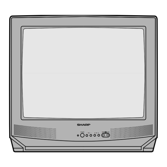
LOCATION OF USER'S CONTROL ........................................................................................ 6
æ
INSTALLATION AND SERVICE INSTRUCTIONS ...................................................................7
æ
CHASSIS LAYOUT ............................................................................................................... 13
æ
BLOCK DIAGRAM ................................................................................................................ 14
æ
SCHEMATIC DIAGRAMS ..................................................................................................... 15
æ
PRINTED WIRING BOARD ASSEMBLIES ........................................................................... 21
æ
REPLACEMENT PARTS LIST .............................................................................................. 27
æ
PACKING OF THE SET ........................................................................................................ 35
SHARP ELECTRONICS CORPORATION
Service Headquarters: Sharp Plaza, Mahwah, New Jersey 07430-2135
SHARP ELECTRONICS OF CANADA LTD.
335 Britannia Road East Mississauga, Ontario L4Z 1W9 Canada
SERVICE MANUAL
COLOR TELEVISION
19J-M100/19J-M100S
19J-M150/CJ19M10
20J-M100/CJ20M10/20MJ10
ELECTRICAL SPECIFICATIONS
SPEAKER
2
(185sq inch)
2
(192sq inch)
ANTENNA INPUT IMPEDANCE
TUNING RANGES
(Nominal)
CONTENTS
SHARP CORPORATION
1
Chassis No. SN-70
OUTPUT RATING ........ 0.9W (at 10% distortion)
SIZE ................................................ 8cm(Round)
VOICE COIL IMPEDANCE ....... 8ohm at 400 Hz
VHF/UHF ............................ 75 ohm Unbalanced
VHF-Channels ....................................... 2thru 13
UHF-Channels .................................... 14thru 69
CATV Channels ................................... 1thru 125
USA: (EIA, Channel Plan)
Specifications are subject to change without prior
notice.
19J-M100/100S/150/20J-M100
CJ19M10/CJ20M10 / 20MJ10
S67A419J-M100
Page
Advertisement
Table of Contents

Related Manuals for Sharp 19J-M100


Summary of Contents for Sharp 19J-M100
-
Page 1: Table Of Contents
æ REPLACEMENT PARTS LIST ....................27 æ PACKING OF THE SET ......................35 SHARP ELECTRONICS CORPORATION Service Headquarters: Sharp Plaza, Mahwah, New Jersey 07430-2135 SHARP ELECTRONICS OF CANADA LTD. 335 Britannia Road East Mississauga, Ontario L4Z 1W9 Canada SHARP CORPORATION... -
Page 2: Important Service Safety Precaution
19J-M100/100S/150/20J-M100 CJ19M10/CJ20M10/ 20MJ10 IMPORTANT SERVICE SAFETY PRECAUTION Service work should be performed only by qualified service technicians who are thoroughly familiar with all safety checks and servicing guidelines which follow: WARNING X-RADIATION AND HIGH VOLTAGE 1. For continued safety, no modification of any circuit LIMITS should be attempted. -
Page 3: Safety Notice
19J-M100/100S/150/20J-M100 CJ19M10/CJ20M10 / 20MJ10 IMPORTANT SERVICE SAFETY PRECAUTION (Continued) BEFORE RETURNING THE RECEIVER Connect the resistor connection to all exposed metal æ parts having a return to the chassis (Fire & Shock Hazard) (antenna, metal cabinet, screw heads, knobs and control shafts, escutcheon, etc.) and measure the... - Page 4 19J-M100/100S/150/20J-M100 CJ19M10/CJ20M10/ 20MJ10 PRECAUTIONS A PRENDRE LORS DE LA REPARATION Ne peut effectuer la réparation qu' un technicien spécialisé qui s'est parfaitement accoutumé à toute vérification de sécurité et aux conseils suivants. AVERTISSEMENT LIMITES DES RADIATIONS X ET DE LA HAUTE TENSION 1.
- Page 5 19J-M100/100S/150/20J-M100 CJ19M10/CJ20M10 / 20MJ10 PRECAUTIONS A PRENDRE LORS DE LA REPARATION (Suite) VERIFICATIONS CONTRE L'INCEN-DIE ET Toucher avec la sonde d'essai les pièces métalliques æ exposées qui présentent une voie de retour au LE CHOC ELECTRIQUE châssis (antenne, coffret métallique, tête des vis, Avant de rendre le récepteur à...
-
Page 6: Location Of User's Control
19J-M100/100S/150/20J-M100 CJ19M10/CJ20M10/ 20MJ10 LOCATION OF USER'S CONTROL 19J-M100/150/100S/CJ19M10/20MJ10... - Page 7 19J-M100/100S/150/20J-M100 CJ19M10/CJ20M10 / 20MJ10 20J-M100/CJ20M10...
-
Page 8: Installation And Service Instructions
After the voltage test,make Y-mute off (normal mode). 4) Connect a digital voltmeter to TP653 and make sure that the voltmeter reads 20.9±1.5V(19J-M100/100S/ M150/CJ19M10),21.5±1.5V(20J-M100/CJ20M10). 5) Apply external 26.8V DC at TP653 by using an external DC supply, TV must be shut off. - Page 9 19J-M100/100S/150/20J-M100 CJ19M10/CJ20M10 / 20MJ10 For adjustments of this model, the bus data is convered to various analog signals by the D-A converter circuit. Note: There are still a few analog adjustments in this series such as focus and master screen voltage.
- Page 10 19J-M100/100S/150/20J-M100 CJ19M10/CJ20M10/ 20MJ10 DATA SERVICE ADJUSTMENT ITEM ADJUSTMENT CONTENTS NUMBER INITIAL VALUE RANGE PICTURE 00-7F TINT 00-7F COLOR 00-7F BRIGHTNESS 00-7F SHARPNESS 00-3F Must be set to “24” VERTICAL PHASE 00-07 Must be set to “00”~"03" HORIZONTAL PHASE 00-1F RF-AGC...
- Page 11 19J-M100/100S/150/20J-M100 CJ19M10/CJ20M10 / 20MJ10 Ë Ë Ë Ë Ë adjustment VCO Adjustment White balance adjustment 1. Connect a digital voltmeter between pin (44) of IC201 1. Have unit receive a good local channel. and ground. 2. Enter the service mode. select service adjustment 2.
- Page 12 19J-M100/100S/150/20J-M100 CJ19M10/CJ20M10/ 20MJ10 "Horizontal position adjustment Sub-color adjustment 1. Have unit receive a good local channel. 1. Have unit receive a good local channel. 2. Make sure the customer color control is set to center 2. Enter the service mode and select service adjustment position .
-
Page 13: Chassis Layout
19J-M100/100S/150 19J-M100/100S/150 CJ19M10/CJ20M10 CJ19M10/CJ20M10 CHASSIS LAYOUT BLOCK DIAGRAM MODEL 20MJ10 20MJ10 MODEL 20MJ10... -
Page 14: Description Of Schematic Diagram
19J-M100/100S/150/CJ19M10/ 19J-M100/100S/150/CJ19M10/ 20J-M100/CJ20M10 20J-M100/CJ20M10 DESCRIPTION OF SCHEMATIC DIAGRAM SCHEMATIC DIAGRAM :CRT Unit 19J-M100/M150 WAVEFORM MEASUREMENT CONDITIONS: CJ19M10 1. Photographs taken on a standard gated color bar NOTE: signal, the tint setting adjusted for proper color. The 1. The unit of resistance "ohm" is omitted (K:1000 wave shapes at the red, green and blue cathodes of ohms, M:1 Meg ohm). - Page 15 19J-M100/100S/150 19J-M100/100S/150 CJ19M10/CJ20M10 CJ19M10/CJ20M10 SCHEMATIC DIAGRAM:MAIN Unit...
-
Page 16: Printed Wiring Board Assemblies
19J-M100/100S/150/CJ19M10/ 19J-M100/100S/150/CJ19M10/ 20J-M100/CJ20M10 20J-M100/CJ20M10 PRINTED WIRING BOARD ASSEMBLIES(19J-M100/150/CJ19M10/CJ20M10) PWB-B:CRT Unit (Wiring Side) SCHEMATIC DIAGRAM :CRT Unit PWB-A:MAIN Unit (Wiring Side) - Page 17 19J-M100/100S/150 19J-M100/100S/150 CJ19M10/CJ20M10 CJ19M10/CJ20M10 PWB-B:CRT Unit (Chip Parts Side) PWB-A:MAIN Unit (Chip Parts Side)
- Page 18 19J-M100/100S/150/CJ19M10/ 19J-M100/100S/150/CJ19M10/ 20J-M100/CJ20M10 20J-M100/CJ20M10 PRINTED WIRING BOARD ASSEMBLIES(19J-M100S) PWB-B CRT PWB (Wiring Side)
- Page 19 19J-M100/100S/150 19J-M100/100S/150 CJ19M10/CJ20M10 CJ19M10/CJ20M10 PWB-B CRT PWB (Chip parts) PWB-A MAIN PWB (Chip parts)
-
Page 20: Parts List
2. NO. DE REF 3. NO. DE PIECE 4. DESCRIPTION in USA: Contact your nearest SHARP Parts Distributor to or- in CANADE: Contact SHARP Electronics of Conada Limited der. For location of SHARP Parts Distributor, Please Phone (416) 890-2100 call Toll-Free; 1-800-BE-SHARP... - Page 21 D501 RH-DX0441CEZZ Diode L406 VP-XF680K0000 68µH RH-DX0110CEZZ L409 VP-XF100K0000 10µH L701 RCiLF0029PEZZ R Coil RH-DX0441CEZZ å D502 RH-DX0131CEZZ Diode RCiLF0087CEZZ (19J-M100/M100S/M150/20J-M100) RCiLF0235CEZZ D601 RH-DX0441CEZZ Diode D603 RH-DX0441CEZZ Diode L701 RCiLF0090CEZZ R Coil å RH-DX0110CEZZ (CJ19M10/CJ20M10) L701 RCiLF0087CEZZ R Coil RH-DX0441CEZZ å...
- Page 22 Mylar C208 VCEA0A1HW474M J 0.47 C209 VCKYCY1HB222K 2200p 50V Ceramic C612 VCFPPJ2EB474J 0.47 250VMetal.P.Film AF C210 VCKYCY1HB102K 1000p 50V Ceramic (19J-M100/150/CJ19M10 m C612 VCFPPJ2EB564J 0.56 250VMetal.P.Film C302 VCCCCY1HH330J Ceramic C303 VCKYCY1HB472K 4700p 50V Ceramic (20J-M100/CJ20M10/ C304 VCEA0A1HW225M J CJ19M10) C631...
- Page 23 19J-M100/100S/150/CJ19M10 20J-M100/CJ20M10/20MJ10 Ref. No. Part No. Description Code Ref. No. Part No. Description Code DUNTK9273WEV0/V2/V4/V5 VRN-MD2AL101J 100 0.1W Metal.Film AA VRN-MD2AL823J 82k 0.1W Metal.Film AA DUNTK9316WEV0/V2 MAIN UNIT VRN-MD2AL223J 22k 0.1W Metal.Film AA å R106 VRS-VV3AB181J 180 1W Metal.OxideAA C2021 VCCCCY1HH101J...
- Page 24 19J-M100/100S/150/CJ19M10 20J-M100/CJ20M10/20MJ10 Ref. No. Part No. Description Code Ref. No. Part No. Description Code DUNTK9273WEV0/V2/V4/V5 R707 VRN-VV3DB1R5J Metal.Film AB å R708 VRD-RM2HD824J 820k 1/2W Carbon MAIN UNIT R709 VRS-KA3NG681J 680 7.0W Metal.OxideAF å å R711 VRS-KA3NG681J 680 7.0W Metal.OxideAF R504...
- Page 25 19J-M100/100S/150/CJ19M10 20J-M100/CJ20M10/20MJ10 Ref. No. Part No. Description Code Ref. No. Part No. Description Code DUNTK9273WEV0/V2/V4/V5 DUNTK9274WEV0/V2 DUNTK9316WEV0/V2 MAIN UNIT DUNTK9317WEV0 CRT UNIT R2049 VRN-MD2AL333J 33k 0.1W Metal.Film AA TRANSISTORS R2054 VRN-MD2AL103J 10k 0.1W Metal.Film AA Q852 VS2SC2229O/1E 2SC2229(O) R2055 VRN-MD2AL103J 10k 0.1W...
-
Page 26: Cabinet Parts
CCABA1266MES2 M Cabinet Front Ass'y P852 QPLGN0461CEZZ Plug M Cabinet Front SC851 QSOCV0840CEZZ Socket GCOVA1031MEKA M Cover QSOCV0826CEZZ HBDGB3009MESA M Badge "sharp" (19J-M100/150/CJ19M10/20J-M100/CJ20M10) JBTN-1090MEKA M Button,CH/VOL-up down AD SC851 QSOCV0913CEZZ GCABB1130MEKA M Rear Cabinet QSOCV0929CEZZ (19J-M100S/20MJ10) 19J-M150 CCABA1266MES1 M Cabinet Front Ass'y... -
Page 27: Miscellaneous Parts
19J-M100/100S/150/CJ19M10 20J-M100/CJ20M10/20MJ10 Ref. No. Part No. Description Code Ref. No. Part No. Description Code MISCELLANEOUS PARTS å QACCD3014CESA M AC Cord QACCD3030CESA QCNW-2110PEZZ Connecting Cord QCNW-2111PEZZ Connecting Cord QCNW-2112PEZZ Connecting Cord VSP0080PBK98A M Speaker VSP0080P-E98S SUPPLIED ACCESORRIES TGAN-1006MEZZ M Guarantee Card... -
Page 28: Packing Of The Set
19J-M100/100S/150/CJ19M10 20J-M100/CJ20M10/20MJ10 Ref. No. Part No. Description Code Ref. No. Part No. Description Code PACKING OF THE SET Polystyrene Bag Operation manual Guarantee Card and batteries Polystyrene mat Buffer material FRONT Packing case Use tapes to fix the packing case. - Page 29 19J-M100/100S/150/CJ19M10 20J-M100/CJ20M10/20MJ10 Ref. No. Part No. Description Code Ref. No. Part No. Description Code TQ0268-S Printed in U.S.A...
Need help?
Do you have a question about the 19J-M100 and is the answer not in the manual?
Questions and answers
Cómo mido si el regulador y el ic lx2942ce está bien
To measure if the regulator and the IC LX2942CE are functioning properly in a Sharp device:
1. Apply 120V AC using a variac transformer.
2. Allow warm-up, then adjust all customer controls for normal picture and sound.
3. Select a local channel.
4. Connect a digital voltmeter to test point TP653. The expected voltage should be:
- 20.9 ± 1.5V for models 19J-M100/100S/M150/CJ19M10
- 21.5 ± 1.5V for models 20J-M100/CJ20M10
5. If the voltage is incorrect, inspect the related circuitry for malfunctioning components.
6. For further testing, apply 26.8V DC to TP653 using an external DC supply — the TV should shut off.
7. To reset the protection circuit, unplug the AC cord and short TP651 to TP652.
These steps help verify if the voltage regulator and IC LX2942CE are operating as intended.
This answer is automatically generated