Table of Contents
Advertisement
14D1-S/G/W
In the interests of user-safety (Required by safety regulations in some countries) the set should be re-
stored to its original condition and only parts identical to those specified should be used.
Ë Multi 18 systems
Ë Full Auto Channel Preset and Auto Channel Skip
Ë 100-CH Program Memory
Ë CATV(Hyper Band) Ready
<Used Frequency Synthesizer Tuner>
Ë AVL(Sound Keeper) Function
Ë Black Stretch Circuit
Ë On Timer/Sleep Timer/Reminder Timer
Ë Blue Back Noise Mute
» SPECIFICATIONS ............................................. 2
» IMPORTANT SERVICE NOTES ........................ 2
» ADJUSTMENT PRECAUTIONS ........................ 3
» MEMORY MAP ................................................ 11
» GA1 HOTEL MODE APPLICATION ................ 15
» TROUBLE SHOOTING TABLE ........................ 15
» WAVEFORMS .................................................. 18
» SOLID STATE DEVICE BASE DIAGRAM ....... 20
» CHASSIS LAYOUT .......................................... 21
» BLOCK DIAGRAM ........................................... 23
» DESCRIPTION OF SCHEMATIC DIAGRAM .. 28
» SCHEMATIC DIAGRAM
Ë CRT UNIT ..................................................... 29
The chassis in this receiver is partially hot. Use an isolation transformer between the line cord plug and power
receptacle, when servicing this chassis. To prevent electric shock, do not remove cover. No user – serviceable
parts inside. Refer servicing to qualified service personnel.
SERVICE MANUAL
14D2-S/G
MODELS
FEATURES
Ë Front Headphone Terminal
Ë Front AV-In & Rear AV-In/Out Terminals
Ë Colour Comb Filter(NTSC only)
Ë High Contrast Picture
Ë Hotel Mode
Ë Arabic/Chinese/English/French/Malay/Russian
Ë White Temperature Adjustment
CONTENTS
Page
WARNING
SHARP CORPORATION
1
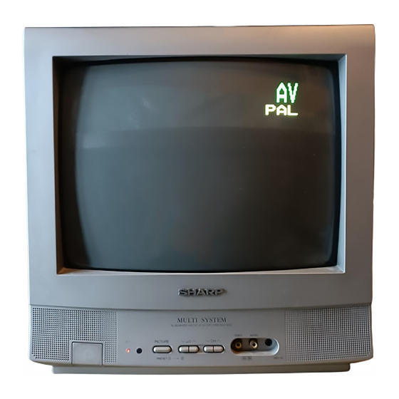
COLOUR TELEVISION
Chassis No. GA-1AM
14D1-S/G/W
14D2-S/G
(Front Priority)
6 Languages OSD
Ë HEAD PHONE UNIT .................................... 29
Ë MAIN UNIT ................................................... 30
» PRINTED WIRING BOARD ASSEMBLIES ..... 34
» REPLACEMENT PARTS LIST
Ë ELECTRICAL PARTS
Main Unit ................................................... 39
Crt Unit ..................................................... 42
Head Phone Unit .................................... 43
Ë SUPPLIED ACCESSORIES ......................... 43
Ë PACKING PARTS ......................................... 43
Ë CABINET PARTS ......................................... 44
» PACKING OF THE SET ................................... 45
14D1-S/G/W
14D2-S/G
SX2T914D-1S//
Page
Advertisement
Table of Contents

Related Manuals for Sharp 14D2-G


Summarization of Contents
Product Overview
Television Features
Lists the various functionalities and capabilities of the television model.
Product Specifications
Details technical parameters like convergence, IF, power, audio, dimensions, and weight.
Service and Safety Precautions
Important Service Notes and X-Ray Safety
Guidelines for qualified service personnel regarding maintenance, X-ray radiation, and pre-return safety checks.
General Safety Notes
General safety advice for handling the equipment and its parts during operation.
Adjustment Procedures
Service Mode Operation and Presetting
Instructions on entering service mode, microprocessor control, and factory presetting.
Picture Adjustments (Purity, PIF, RF-AGC)
Detailed steps for Purity, PIF, and RF-AGC adjustments.
Picture Adjustments (Convergence, White Balance)
Procedures for adjusting convergence and white balance settings.
Picture Adjustments (Deflection, Chroma)
Steps for adjusting deflection loop, PAL, and NTSC chroma settings.
Function Operation Checks
Procedures for checking video and audio functions like contrast, color, and sound system.
Technical Diagrams and Troubleshooting
Troubleshooting Table
Diagnostic steps and tables for identifying and resolving common TV issues.
Hotel Mode Application
Guide on how to enable and use the Hotel Mode feature on the TV.
Waveforms Reference
Visual representations of various test signals and waveforms for troubleshooting.
Solid State Device Base Diagrams
Diagrams showing the pinouts and physical layout of various semiconductor devices.
Chassis and Block Diagrams
Layouts of chassis boards and functional block diagrams for key units.
Schematic Diagrams
Detailed circuit diagrams for CRT, Headphone, and Main units.
Printed Wiring Board Assemblies
Wiring and component placement diagrams for main, CRT, and headphone PCBs.
Parts and Packing Information
Replacement Parts List
Comprehensive list of all replacement parts, including integrated circuits, transistors, diodes, capacitors, and resistors.
Cabinet Parts
List and location diagrams for replacement cabinet parts.
Packing of the Set
Illustration showing the proper packing method for the television set.
Need help?
Do you have a question about the 14D2-G and is the answer not in the manual?
Questions and answers