Table of Contents
Advertisement
Quick Links
POW ER
- VOL
+
CH
MEN U
In the interests of user-safety (Required by safety regulations in some countries) the set should be restored to its
original condition and only parts identical to those specified should be used.
» ELECTRICAL SPECIFICATIONS ......................................................................................................... 1
» IMPORTANT SERVICE SAFETY PRECAUTION ................................................................................. 2
» LOCATION OF USER'S CONTROL ..................................................................................................... 6
» INSTALLATION AND SERVICE INSTRUCTIONS ................................................................................ 7
» CHASSIS LAYOUT ............................................................................................................................. 13
» BLOCK DIAGRAM .............................................................................................................................. 15
» SCHEMATIC DIAGRAMS ................................................................................................................... 17
» PRINTED WIRING BOARD ASSEMBLIES ........................................................................................ 26
» REPLACEMENT PARTS LIST ............................................................................................................ 29
» PACKING OF THE SET ...................................................................................................................... 37
POWER INPUT ..................................................... AC 120 V, 60 Hz
POWER RATING .................................................................... 69 W
PICTURE SIZE ........................................... 1,194cm
CONVERGENCE ............................................................. Magnetic
SWEEP DEFLECTION .................................................... Magnetic
FOCUS ............................................... Hi-Bi-Potential Electrostatic
INTERMEDIATE FREQUENCIES
Picture IF Carrier Frequency ..................................... 45.75 MHz
Sound IF Carrier Frequency ...................................... 41.25 MHz
Color Sub-Carrier Frequency .................................... 42.17 MHz
AUDIO POWER
OUTPUT RATING ..................................................... 1 W (RMS)
SHARP CORPORATION
SERVICE MANUAL
MODELS
CONTENTS
ELECTRICAL SPECIFICATIONS
SPEAKER
SIZE ...................................................................... 8 cm (Round)
2
(185sq inch)
VOICE COIL IMPEDANCE ............................. 32 ohm at 400 Hz
ANTENNA INPUT IMPEDANCE
VHF/UHF ..................................................... 75 ohm Unbalanced
TUNING RANGES
VHF-Channels ............................................................... 2 thru 13
UHF-Channels ............................................................ 14 thru 69
CATV Channels ........................................................... 1 thru 125
(Nominal)
Specifications are subject to change without
prior notice.
This document has been published to be used for after
sales service only.
The contents are subject to change without notice.
1
COLOR TELEVISION
Chassis No. SN-010
19U-M100, 19U-M100S
CU19M10
19U-M100,19U-M100S
CU19M10
S12E719U-M100
Page
(EIA, Channel Plan U.S.A.)
Advertisement
Table of Contents

Related Manuals for Sharp 19U-M100


Summary of Contents for Sharp 19U-M100
-
Page 1: Table Of Contents
19U-M100,19U-M100S CU19M10 SERVICE MANUAL S12E719U-M100 COLOR TELEVISION Chassis No. SN-010 19U-M100, 19U-M100S POW ER – VOL MEN U CU19M10 MODELS In the interests of user-safety (Required by safety regulations in some countries) the set should be restored to its original condition and only parts identical to those specified should be used. -
Page 2: Important Service Safety Precaution
19U-M100,19U-M100S CU19M10 IMPORTANT SERVICE SAFETY PRECAUTION Ë Service work should be performed only by qualified service technicians who are thoroughly familiar with all safety checks and the servicing guidelines which follow: WARNING X-RADIATION AND HIGH VOLTAGE LIMITS 1. For continued safety, no modification of any circuit 1. -
Page 3: Safety Notice
19U-M100,19U-M100S CU19M10 IMPORTANT SERVICE SAFETY PRECAUTION (Continued) » Connect the resistor connection to all exposed metal BEFORE RETURNING THE RECEIVER parts having a return to the chassis (antenna, metal (Fire & Shock Hazard) cabinet, screw heads, knobs and control shafts, escutcheon, etc.) and measure the AC voltage drop... - Page 4 19U-M100,19U-M100S CU19M10 PRECAUTIONS A PRENDRE LORS DE LA REPARATION Ë Ne peut effectuer la réparation qu' un technicien spécialisé qui s'est parfaitement accoutumé à toute vérification de sécurité et aux conseils suivants. AVERTISSEMENT LIMITES DES RADIATIONS X ET DE LA HAUTE TENSION 1.
- Page 5 19U-M100,19U-M100S CU19M10 PRECAUTIONS A PRENDRE LORS DE LA REPARATION (Suite) » Toucher avec la sonde d'essai les pièces métalliques VERIFICATIONS CONTRE L'INCEN-DIE ET exposées qui présentent une voie de retour au LE CHOC ELECTRIQUE châssis (antenne, coffret métallique, tête des vis, Avant de rendre le récepteur à...
-
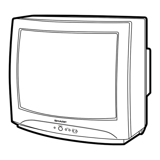
Page 6: Location Of User's Control
19U-M100,19U-M100S CU19M10 LOCATION OF USER'S CONTROL Front Panel POWER – VOL + MENU SENSOR AREA FOR REMOTE CONTROL POWER – VOL + MENU POWER Press CHANNEL UP/DOWN – MENU VOLUME UP/DOWN Press again Off. ) Selects next higher channel. (+) Increases sound. -
Page 7: Installation And Service Instructions
19U-M100,19U-M100S CU19M10 INSTALLATION AND SERVICE INSTRUCTIONS Note: (1) When performing any adjustments to resistor controls and transformers use non-metallic screwdrivers or TV alignment tools. (2) Before performing adjustments, the TV set must be on at least 15 minutes. HIGH VOLTAGE CHECK CIRCUIT PROTECTION The receiver is protected by a 4.0A fuse (F701),... - Page 8 19U-M100,19U-M100S CU19M10 For adjustments of this model, the bus data is converted to various analog signals by the D/A converter circuit. Note: There are still a few analog adjustments in this series such as focus and master screen voltage. Follow the steps below whenever the service adjusment is required.
- Page 9 AFC GAIN 00, 01 G DRIVE 00, 0F FBT BLK SW 00, 01 V COMP 00-07 OSD CONT 00-07 SHARPNESS 00-3F 19(Matsushita Tuner),11(SHARP Tuner) FLT SYS 00-03 KILLER OP 00-07 PRE SHOOT 00-03 CORING 00-07 DC REST 00-03 BS START...
- Page 10 19U-M100,19U-M100S CU19M10 Holding down both the Vol-up/Ch-down buttons on the TV set at service mode for more than 2 seconds will automatically write the above initial values into IC2101. ADJUSTMENT PART REPLACED NOTES NECESSARY UNNECESSARY IC2001 Data is stored in IC2101.
-
Page 11: Service Adjustment
19U-M100,19U-M100S CU19M10 Ë SERVICE ADJUSTMENT RF AGC Adjustment White Balance Adjustment 1. Receive a good local channel. 1. Receive a good local channel. 2. Enter the service mode signal category and select 2. Select the service adjustment "S12" and set the data the service adjustment "S01". - Page 12 19U-M100,19U-M100S CU19M10 Vertical-Size, V-Linearity and V-S Correction Adjustments 1. Receive a good local channel. 2. Enter the service mode DEF category and select the adjustment "D02" for Vertical Size, "D05" for V- Linearity and "D06" for V-S Correction Adjustment. 3. Set in order "D05" for V-Linearity, "D06" for V-S Correction and set the data to get the best linearity.
-
Page 13: Chassis Layout
19U-M100,19U-M100S CU19M10 MODELS 19U-M100/100S CHASSIS LAYOUT Ë 19U-M100 Ë 19U-M100S... - Page 14 19U-M100,19U-M100S CU19M10 MODEL CU19M10 CHASSIS LAYOUT...
-
Page 15: Block Diagram
19U-M100,19U-M100S CU19M10 MODELS 19U-M100/100S BLOCK DIAGRAM... - Page 16 19U-M100,19U-M100S CU19M10 MODEL CU19M10 BLOCK DIAGRAM...
-
Page 17: Schematic Diagrams
19U-M100,19U-M100S CU19M10 DESCRIPTION OF SCHEMATIC DIAGRAM WAVEFORM MEASUREMENT CONDITIONS: NOTES: 1. Photographs taken on a standard gated color bar 1. The unit of resistance "ohm" is omitted. signal, the tint setting adjusted for proper color. The (K=k =1000 , M=M ) wave shapes at the red, green and blue cathodes of 2. - Page 18 19U-M100,19U-M100S CU19M10 MODEL 19U-M100 SCHEMATIC DIAGRAM: MAIN Unit...
- Page 19 19U-M100,19U-M100S CU19M10 MODEL 19U-M100S SCHEMATIC DIAGRAM: MAIN Unit...
- Page 20 19U-M100,19U-M100S CU19M10 MODEL CU19M10 SCHEMATIC DIAGRAM: MAIN Unit...
- Page 21 19U-M100,19U-M100S CU19M10 MODEL 19U-M100 SCHEMATIC DIAGRAM: CRT Unit...
- Page 22 19U-M100,19U-M100S CU19M10 MODELS 19U-M100S, CU19M10 SCHEMATIC DIAGRAM: CRT Unit...
-
Page 23: Printed Wiring Board Assemblies
19U-M100,19U-M100S CU19M10 PRINTED WIRING BOARD ASSEMBLIES PWB-A: MAIN Unit (Wiring Side) - Page 24 19U-M100,19U-M100S CU19M10 PWB-A: MAIN Unit (Chip Parts Side)
- Page 25 19U-M100,19U-M100S CU19M10 PWB-B: CRT Unit (Wiring Side) PWB-B: CRT Unit (Chip Parts Side)
-
Page 26: Printed Wiring Board Assemblies
2. NO. DE REF 3. NO. DE PIECE 4. DESCRIPTION in USA: Contact your nearest SHARP Parts Distributor to order. For in CANADA: Contact SHARP Electronics of Canada Limited location of SHARP Parts Distributor, Please call Toll-Free; 1- Phone (416) 890-2100... -
Page 27: Main Unit
Q631 VS2SC945AQ/-1 J 2SC945AQ D704 RH-DX0490CEZZ J Diode å VS2SC3198-Y-1 RH-DX0154CEZZ Q701 VSSPP04N60C-1 J SPP04N60C å D705 RH-DX0048GEZZ J Diode (19U-M100, 19U-M100S) VSSPP07N60C-1 VHD1SS119//-1 D707 RH-DX0475CEZZ J Diode VS2SK2708//1E VHD1SS244//-1 VS2SK2645//-G D708 RH-DX0475CEZZ J Diode VSSTP6NC60+-1 VHD1SS244//-1 D709 RH-DX0229CEZZ J Diode å... - Page 28 D758 RH-DX0131CEZZ J Diode C401 VCCCCY1HH470J J 47p Ceramic VA701 RH-VX0019CEZZ J Varistor å C411 VCEA0A1AW108M J 1000 10V (19U-M100, 19U-M100S) C412 VCKYCY1HB103K J 0.01 Ceramic RH-VX0035CEZZ C414 VCEA0A1HW225M J 2.2 C416 VCEA0A1HW105M J 1.0 RH-VX0048CEZZ C418 VCKYCY1HB103K J 0.01...
- Page 29 R403 VRS-CY1JF101J J 100 1/16W M-Ox. C753 VCKYPH3DB561K J 560p 2kV Ceramic R404 VRD-RA2BE102J J 1.0k 1/8W Carbon (19U-M100, 19U-M100S) R411 VRS-CY1JF684J J 680k 1/16W M-Ox. C754 VCEA0A1CW476M J 47 R412 VRS-CY1JF391J J 390 1/16W M-Ox. C758 VCEA0A2EW106M J 10 250V EL.
- Page 30 19U-M100,19U-M100S CU19M10 Ref. No. Part No. Description Code Ref. No. Part No. Description Code PWB-A:DUNTKA358WEX9(19U-M100) R2024 VRD-RA2BE682J J 6.8k 1/8W Carbon PWB-A:DUNTKA358WEY0(19U-M100S) R2025 VRD-RA2BE682J J 6.8k 1/8W Carbon PWB-A:DUNTKA358WEY1(CU19M10) R2026 VRD-RA2BE682J J 6.8k 1/8W Carbon R2027 VRD-RA2BE682J J 6.8k 1/8W...
-
Page 31: Crt Unit
19U-M100,19U-M100S CU19M10 Ref. No. Part No. Description Code Ref. No. Part No. Description Code PWB-A:DUNTKA358WEX9(19U-M100) PWB-B:DUNTKA359WEV2(19U-M100) PWB-A:DUNTKA358WEY0(19U-M100S) PWB-B:DUNTKA359WEV1(19U-M100S, PWB-A:DUNTKA358WEY1(CU19M10) CU19M10) MAIN UNIT (Continued) CRT UNIT TRANSISTORS FB351 RBLN-0091GEZZ J Ferrite Bead Q852 RH-TX0110BMZZ+ R TX0110BM RBLN-0047CEZZ FB601 RBLN-0047CEZZ J Ferrite Bead... -
Page 32: Packing Parts
— (19U-M100S/CU19M10) SPAKP0098PEZZ – Wrapping Paper — QSOCV0933CEZZ SPAKX2701PEZZ – Buffer Material — SC852 QSOCV0841CEZZ J CRT Socket (19U-M100) SSAKA0001PEZZ – Polyethylene Bag — QSOCV0840CEZZ MISCELLANEOUS PARTS SUPPLIED ACCESSORIES ACC701 QACCD3064CESA J AC Cord (AC120V/60Hz) RRMCG1324CESA R Infrared R/C Unit å... -
Page 33: Cabinet Parts
19U-M100,19U-M100S CU19M10 Ref. No. Part No. Description Code Ref. No. Part No. Description Code CABINET PARTS CABINET PARTS LOCATION CCABA2713WEV0 R Front Cabinet Ass’y (19U-M100/100S) CCABA2713WEV1 R Front Cabinet Ass’y (CU19M10) Not Available – Front Cabinet — GCOVA0069PEKA J LED Cover... -
Page 34: Packing Of The Set
19U-M100,19U-M100S CU19M10 PACKING OF THE SET Polyethylene Bag Operation Manual Guarantee Card (19U-M100/100S) Batteries Polyethylene Mat Infrared R/C unit Buffer Material FRONT Packing Case Use 22 staples to fix the bottom side REAR of packing case. MARK : Not replacement items. - Page 35 19U-M100,19U-M100S CU19M10 COPYRIGHT © 2002 BY SHARP CORPORATION ALL RIGHTS RESERVED. No part of this publication may be reproduced, stored in a retrieval system, or transmitted in any form or by any means, electronic, mechanical, photocopying, recording, or otherwise, without prior written permission of the publisher.
Need help?
Do you have a question about the 19U-M100 and is the answer not in the manual?
Questions and answers