Dimplex EUH-B Quick Manual
Electric unit heaters
Hide thumbs
Also See for EUH-B:
- Installation and operation manual (3 pages) ,
- Installation instructions (3 pages)
Advertisement
Quick Links
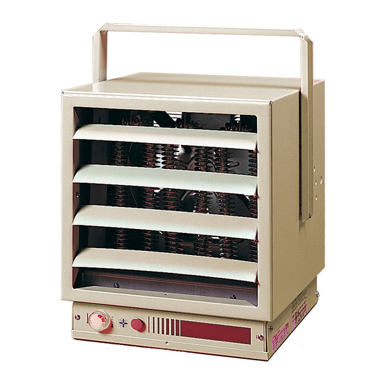
ELECTRIC UNIT HEATERS
MODEL EUH-B
Installation/ Start-up/ Maintenance
FOR HORIZONTAL OR VERTICAL AIRFLOW
PERMANENT OR SUPPLEMENTARY ELECTRIC FORCED AIR HEATING FROM THE SAME
VERSATILE UNIT
These heavy-duty heaters provide spot heating for hard to heat areas, or they can be used as the
primary
source of heat for areas not reached by an existing heating system.
The fan and motor are carefully matched to insure quiet, trouble-free operation and fan blades are precision
balanced before installation.
Heaters in all capacities (3, 5, 7-1/2, 10 or 12kw) have the same dimensions, and use the same mounting
brackets. All components and controls, including thermostat, transformers, relays, and switches are
enclosed inside the case. Wiring is simple and all heaters can operate from a single power source.
1. HEATER LOCATION: Unit heaters should be located along outside walls to provide perimeter air
circulation. The discharge air should wipe the walls without blowing directly on them. (Figure 1)
a. Small rooms - can be heated by one or two units. Locate the unit heater(s) to provide circular air
movement within the space.
b. Large rooms - requiring multiple unit installations. Units should be located so that the discharge air from
one unit supports the discharge from another unit and provides a circular air movement.
c. Remote thermostats - should be located on interior walls or posts away from heat sources, cold drafts,
and away from heater discharge streams.
2. MOUNTING UNIT HEATER(S): Heater should be mounted a minimum of ten (10) inches from walls
and six (6) feet above fl oor (8 feet for vertical air fl ow) with the discharge parallel to or away from wall.
(See Table A for recommended mounting heights)
a. MOUNTING BRACKET - The heater is shipped with a mounting bracket packed separately in the carton.
Secure the bracket to threaded attachment points on the sides of the heater with two bolts (provided).
Select desired angle of tilt (Horizontal, 15, 30, 45, 60, 75, or Vertical), remove corresponding knockouts
on sides of the heater, then screw the remaining two bolts into the threaded holes in the bracket so that
the bolts pass through the knockout holes. The unit is now ready for hanging.
b. CEILING MOUNTING - Fasten the heater securely to the ceiling using the center hole in the bracket
or the two holes on either side of the center hole. The Unit mounting bracket may be attached directly to
the ceiling.
c.WALL MOUNTING - The heater may also be mounted to a wall with accessory wall bracket,
(Part # EUHWB). The wall bracket attaches to the center hole of the unit mounting bracket.
EXPOSED OUTSIDE WALL
EXPOSED OUTSIDE WALL
SMALL ROOM
LARGE ROOM
FIGURE 1
7202450001R05
1-888-346-7539
Advertisement

Related Manuals for Dimplex EUH-B


Summary of Contents for Dimplex EUH-B
- Page 1 ELECTRIC UNIT HEATERS MODEL EUH-B Installation/ Start-up/ Maintenance FOR HORIZONTAL OR VERTICAL AIRFLOW PERMANENT OR SUPPLEMENTARY ELECTRIC FORCED AIR HEATING FROM THE SAME VERSATILE UNIT These heavy-duty heaters provide spot heating for hard to heat areas, or they can be used as the primary source of heat for areas not reached by an existing heating system.
- Page 2 Heater is now ready for wiring 3. WIRING: a. Connect the heater only to the voltage and frequency specifi ed on the nameplate. b. All wiring to be in accordance with local and national electric codes. c. Remove two screws securing the access door (See Figure 2) and swing the door down to expose the wiring and control compartment.
- Page 3 c. Fan only Switch - An optional “Fan only” switch kit (Catalogue EUAF2) is available for fi eld installation in the unit. The fan switch is mounted in the space provided adjacent to the built-in thermostat located at the front of the unit. Field connections are made at the control terminal block in accordance with the unit wiring diagram.
- Page 4 REPLACEMENT PARTS CATALOG NO. FAN BLADE FAN DELAY GRILL LOUVER MOTOR TERM BLOCK THERMOSTAT TRANSFORMER EUH03B11T 530020300RP 2000250100RP 2600060800RP EUH03B21T EUH03B24CT EUH03B31T EUH03B34CT EUH03B41T 2600060200RP 21001200100RP EUH03B51CT 2100120200RP EUH03B73CT 2100120400RP EUH03B81CT 2100120500RP EUH03B83CT 5300020100RP 2100120500RP EUH05B21T 2600060800RP EUH05B24CT 2600060200RP EUH05B31T 2600060800RP EUH05B34CT 2600060200RP...
- Page 5 ELEMENT CATALOG NO. CAPACITOR CASING CONTACTOR CONTROL KNOB CUT-OUT RP NO. QTY/HEATER EUH03B11T 3200070600RP 2200210100RP EUH03B21T 2200210200RP EUH03B24CT 2400170900RP 2200210200RP EUH03B31T 2200210300RP EUH03B34CT 2400170900RP 2200210300RP EUH03B41T 2200210400RP EUH03B51CT 2400160300RP 2200211200RP EUH03B73CT 2400160300RP 2200210400RP EUH03B81CT 2400160300RP 2200212100RP EUH03B83CT 2400160300RP 2200211200RP EUH05B21T 2200210800RP EUH05B24CT 2400170900RP...