
Related Manuals for Supero X8DTT


Summary of Contents for Supero X8DTT
- Page 1 X8DTT X8DTT-F X8DTT-IBX X8DTT-IBXF X8DTT-IBQ X8DTT-IBQF USER’S MANUAL Revision 1.0b...
- Page 2 The information in this User’s Manual has been carefully reviewed and is believed to be accurate. The vendor assumes no responsibility for any inaccuracies that may be contained in this document, makes no commitment to update or to keep current the information in this manual, or to notify any person or organization of the updates.
-
Page 3: About This Manual
X8DTT/ X8DTT-F/X8DTT-IBX/X8DTT-IBXF/X8DTT-IBQ/X8DTT-IBQF motherboard. About This Motherboard X8DTT Series motherboards support the Intel 5500/5600 Series Processor platform and the QuickPath Interconnect (QPI) Technology, providing the next generation point-to-point system interface, replacing the current Front Side Bus. With the 5500/5600 Series Processor built-in, the X8DTT/-F/-IBX/-IBXF/-IBQ/-IBQF... -
Page 4: Conventions Used In The Manual
X8DTT/-F/-IBX/-IBXF/-IBQ/-IBQF User's Manual Conventions Used in the Manual Special attention should be given to the following symbols for proper installation and to prevent product damage or bodily injury: Warning: Important information given to ensure proper system installation or to prevent damage to the components. -
Page 5: Contacting Supermicro
Contacting Supermicro Contacting Supermicro Headquarters Address: Super Micro Computer, Inc. 980 Rock Ave. San Jose, CA 95131 U.S.A. Tel: +1 (408) 503-8000 Fax: +1 (408) 503-8008 Email: marketing@supermicro.com (General Information) support@supermicro.com (Technical Support) Web Site: www.supermicro.com Europe Address: Super Micro Computer B.V. Het Sterrenbeeld 28, 5215 ML 's-Hertogenbosch, The Netherlands Tel:... -
Page 6: Table Of Contents
Universal Serial Bus (USB) ..............2-16 Ethernet Ports ..................2-17 Serial Ports ....................2-18 Video Connector ..................2-18 Infi niBand Connection (X8DTT-IBX/IBXF/IBQ/IBQ/IBQF) ......2-19 Unit Identifi er Switches ................2-20 Front Control Panel ..................2-21 Front Control Panel Pin Defi nitions............... 2-22 Power LED .................... - Page 7 BMC Enable (For X8DTT-F/IBXF/IBQF only) .......... 2-36 Onboard Indicators ..................2-37 GLAN LEDs ....................2-37 BMC Heartbeat LED (X8DTT-F/IBX-F/IBQF) ........... 2-37 Infi niBand LED Indicators (LEB1/LEB2) (X8DTT-IBX/IBXF/IBQ/IBQF) ... 2-38 ..............2-38 Onboard Power LED 2-10 Serial ATA and PCI-E Connections ............... 2-39 Serial ATA Ports..................
- Page 8 X8DTT/-F/-IBX/-IBXF/-IBQ/-IBQF User's Manual Boot Confi guration ..................4-26 Exit Options ....................4-27 Appendix A BIOS Error Beep Codes BIOS Error Beep Codes ................. A-1 Appendix B Software Installation Instructions Installing Software Programs ................B-1 Confi guring Super Doctor® III ................. B-2...
-
Page 9: Chapter 1 Introduction
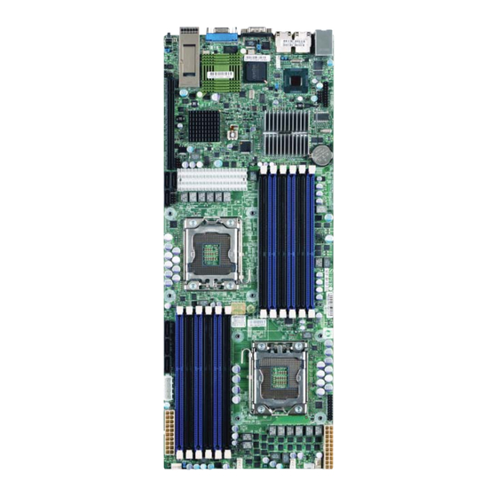
Chapter 1: Introduction Chapter 1 Introduction Overview Checklist Congratulations on purchasing your computer motherboard from an acknowledged leader in the industry. Supermicro boards are designed with the utmost attention to detail to provide you with the highest standards in quality and performance. Check that the following items have all been included with your motherboard. - Page 10 X8DTT/-F/-IBX/-IBXF/-IBQ/-IBQF User's Manual X8DTT/-F/-IBX/-IBXF/-IBQ/-IBQF Motherboard Image Model Variations (Differences between X8DTT models) X8DTT /-IBX /-IBXF /-IBQ /IBQF IPMI 2.0 w/ KVM Over Infi niBand Connect. DDR IB QDR IB Note: The drawings and pictures shown in this manual were based on the latest PCB Revision available at the time of publishing of the manual.
- Page 11 Chapter 1: Introduction X8DTT/-F/-IBX/-IBXF/-IBQ/-IBQF Motherboard Layout COM1 USB0/1 InfiniBand JNMI1 Connector JWD1 LAN2 LAN1 IPMI_LAN JPG1 Nuvoton InfiniBand CTRL WPCM450 LAN CTRL JWOL1 JBT1 Intel ICH-10R Intel (South Bridge) 5520/5500 BIOS (North Bridge) JBAT1 Battery X8DTT Series Rev. 2.0 CPU2...
- Page 12 X8DTT/-F/-IBX/-IBXF/-IBQ/-IBQF User's Manual X8DTT/-F/-IBX/-IBXF/-IBQ/-IBQF Quick Reference COM1 USB0/1 InfiniBand JNMI1 Connector JWD1 LAN2 LAN1 IPMI_LAN JPG1 Nuvoton WPCM450 InfiniBand CTRL LAN CTRL JWOL1 JBT1 Intel ICH-10R Intel (South Bridge) 5520/5500 BIOS (North Bridge) JBAT1 Battery X8DTT Series Rev. 2.0 CPU2...
- Page 13 COM1 COM1 Serial Port FAN 1-4 System/CPU Fan Headers Infi niBand Infi niBand Connector (X8DTT-/IBX/IBXF/IBQ/IBQF) IPMB IPMB Header (for an IPMI Card) (X8DTT-F/-IBXF/-IBQF) J119 Infi niBand I C Debug Header (-/IBX/IBXF/IBQ/IBQF) Front Panel Connector JNMI1 NMI (Non-Maskable Interrupt) Header JP10...
-
Page 14: Motherboard Features
Power-up mode control for recovery from AC power loss • Auto-switching voltage regulator for CPU cores • System overheat/Fan Fail LED Indicator and control • System resource alert via Supero Doctor III ACPI Features • Slow blinking LED for suspend state indicator • Main switch override mechanism... - Page 15 Nuvoton WPCM450 BMC (Baseboard Management Controller) supports IPMI 2.0 with KVM support (X8DTT-F/-IBXF/-IBQF) • Intel 82576 Dual-LAN Gigabit Ethernet Controller supports dual Giga-bit LAN ports • Onboard PHY Chip supports IPMI dedicated LAN (X8DTT-F/-IBXF/-IBQF) • One COM port • Infi niBand Connector •...
- Page 16 X8DTT/-F/-IBX/-IBXF/-IBQ/-IBQF User's Manual PROCESSOR#0 PROCESSOR#1 Port1 Port0 Ports 2,1 MT25408 Kawela Connect-X IB QSFP Ports PCI-E Gen2/DDR or QDR (Depupulate for 5500) Intel 5520/5500 Ports RJ45 RJ45 Ports 7,8,9,10 SST25 VF016 CLINK CLINK ICH10R PE 4-1 SATA SATA #1 SATA #2...
-
Page 17: Chipset Overview
Chipset Overview Built upon the functionality and the capability of the 5500/5600 Series Processor platform, the X8DTT/-F/-IBX/-IBXF/-IBQ/-IBQF motherboard provides the perfor- mance and feature set required for dual-processor-based systems with confi gu- ration options optimized for intensive applications, High Performance Computing (HPC)/Cluster and server platforms. -
Page 18: Special Features
Setup section to change this setting. The default setting is Last State. PC Health Monitoring This section describes the PC health monitoring features of the X8DTT/-F/-IBX/- IBXF/-IBQ/-IBQF. All have an onboard System Hardware Monitor chip that sup- ports PC health monitoring. An onboard voltage monitor will scan these onboard voltages continuously: CPU1 VCore, CPU2 VCore, +5Vin, 12Vcc (V), VP1 DIMM,... -
Page 19: Acpi Features
Chapter 1: Introduction Super Doctor to provide you with warnings when the system temperature, CPU temperatures, voltages and fan speeds go beyond a pre-defi ned range. ACPI Features ACPI stands for Advanced Confi guration and Power Interface. The ACPI specifi ca- tion defi... -
Page 20: Power Supply
fi lter to shield the computer from noise. It is recommended that you also install a power surge protector to help avoid problems caused by power surges. Note: The X8DTT/-F/-IBX/-IBXF/-IBQ/-IBQF supports proprietary power connectors. Please refer to Page 2-21 for detailed information on power supply for the motherboard. -
Page 21: Chapter 2 Installation
Chapter 2: Installation Chapter 2 Installation Standardized Warning Statements The following statements are industry-standard warnings, provided to warn the user of situations which have the potential for bodily injury. Should you have questions or experience diffi culty, contact Supermicro's Technical Support department for assis- tance. - Page 22 X8DTT/-F/-IBX/-IBXF/-IBQ/-IBQF User's Manual Attention ﺍﻟﻘﻮﺍﻧﻴﻦ ﻭﺍﻟﻠﻮﺍﺋﺢ ﺍﻟﻮﻁﻨﻴﺔ ﺠﻤﻴﻊ ﻭﻓﻘﺎ ﻟ ﻳﻨﺒﻐﻲ ﺍﻟﺘﻌﺎﻣﻞ ﻣﻌﻪ ﻫﺬﺍ ﺍﻟﻤﻨﺘﺞ ﻣﻦ ﺍﻟﺘﺨﻠﺺ ﺍﻟﻨﻬﺎﺋﻲ ﻋﻨﺪ Danger d'explosion si la pile n'est pas remplacée correctement. Ne la remplacer que par une pile de type semblable ou équivalent, recommandée par le fabricant.
-
Page 23: Product Disposal
Chapter 2: Installation Product Disposal Warning! Ultimate disposal of this product should be handled according to all national laws and regulations. 警告 本产品的废弃处理应根据所有国家的法律和规章进行。 警告 本產品的廢棄處理應根據所有國家的法律和規章進行。 Warnung Die Entsorgung dieses Produkts sollte gemäß allen Bestimmungen und Gesetzen des Landes erfolgen. ¡Advertencia! Al deshacerse por completo de este producto debe seguir todas las leyes y regla- mentos nacionales. -
Page 24: Static-Sensitive Devices
X8DTT/-F/-IBX/-IBXF/-IBQ/-IBQF User's Manual Waarschuwing De uiteindelijke verwijdering van dit product dient te geschieden in overeenstemming met alle nationale wetten en reglementen. Static-Sensitive Devices Electrostatic Discharge (ESD) can damage electronic com ponents. To prevent dam- age to your system board, it is important to handle it very carefully. The following measures are generally suffi... -
Page 25: Motherboard Installation
Locations of Mounting Holes Tools Needed 1. Phillips Screwdriver 2. Pan head #6 screws X8DTT Series Installation Instructions Rev. 2.0 1. Install the IO shield into the chassis. 2. Locate the mounting holes on the mother- board. -
Page 26: Processor And Heatsink Installation
X8DTT/-F/-IBX/-IBXF/-IBQ/-IBQF User's Manual Processor and Heatsink Installation Warning: When handling the processor package, avoid placing direct pressure on the label area of the fan. Notes: 1. Always connect the power cord last and always remove it before adding, re- moving or changing any hardware components. Make sure that you install the processor into the CPU socket before you install the CPU heatsink. - Page 27 Chapter 2: Installation 4. After removing the plastic cap, using your thumb and the index fi nger, hold the CPU at the north and south center edges. 5. Align the CPU key, the semi-circle cutout, against the socket key, the notch below the gold color dot on the side of the socket.
-
Page 28: Installing A Cpu Heatsink
X8DTT/-F/-IBX/-IBXF/-IBQ/-IBQF User's Manual Installing a CPU Heatsink 1. Do not apply any thermal grease to the heatsink or the CPU die because the required amount has already been ap- plied. Screw#1 Screw#2 2. Place the heatsink on top of the... - Page 29 Chapter 2: Installation Removing the Heatsink Warning: We do not recommend that the CPU or the heatsink be removed. However, if you do need to remove the heatsink, please follow the instructions below to uninstall the heatsink and prevent damage to the CPU or other components. 1.
-
Page 30: Memory Installation
X8DTT/-F/-IBX/-IBXF/-IBQ/-IBQF User's Manual Memory Installation Note: Check the Supermicro web site for recommended memory modules. CAUTION Exercise extreme care when installing or removing DIMM modules to prevent any possible damage. Also note that the memory is interleaved to improve performance (See step 1). -
Page 31: Memory Support
Chapter 2: Installation Memory Support This motherboard supports up to 192 GB of Registered ECC or 48 GB of Unbuffered ECC/Non-ECC DDR3 1333/1066/800 MHz Memory in 12 DIMMs. Also, memory speed support is dependent on the type of CPU used on the board. DIMM Module Population Confi... - Page 32 X8DTT/-F/-IBX/-IBXF/-IBQ/-IBQF User's Manual Memory Support for the Motherboard w/5600 Processors Installed • 1.5V DIMMs 1.5V RDIMM Population for the Motherboard w/5600 Processors Installed DIMM DIMMs DIMM Type (Reg.= Speeds (in MHz) Ranks per DIMM Slots per Populated Registered) (any combination;...
- Page 33 Chapter 2: Installation 1.35V UDIMM Population for the Motherboard w/5600 Processors Installed DIMM DIMMs DIMM Type (Unb.= Speeds (in MHz) Ranks per DIMM Slots per Populated Unbuffered) (any combination; Channel per Channel SR=Single Rank, DR=Dual Rank, QR=Quad Rank) Unb. DDR3 ECC 800,1066,1333 SR or DR Unb.
- Page 34 X8DTT/-F/-IBX/-IBXF/-IBQ/-IBQF User's Manual Installing and Removing DIMMs DIMM DDR3 Notch Notch Release Note: Notch Release should align with the receptive point X8DTT Series Rev. 2.0 on the slot To Install: Insert module vertically and press down until it snaps into place. Pay attention to the alignment notch at the bottom.
-
Page 35: Control Panel Connectors/Io Ports
Back Panel Connectors 1. USB 0 2. USB 1 3. IPMI_Dedicated LAN (X7DTT-F/-IBXF/- IBQF models) 4. LAN 1 5. LAN 2 X8DTT Series 6. COM Port 1 (Black) Rev. 2.0 7. VGA (Blue) 8. Infi niBand (X8DTT-IBX/-IBXF/-IBQ/-IBQF models) 9. UID Switch 2-15... -
Page 36: Back Panel Connector Pin Defi Nitions
X8DTT/-F/-IBX/-IBXF/-IBQ/-IBQF User's Manual Back Panel Connector Pin Defi nitions Universal Serial Bus (USB) Back Panel USB 0/1 Pin Defi nitions Two Universal Serial Bus ports (USB Pin# Defi nition Pin# Defi nition 0/1) are located on the I/O back panel. -
Page 37: Ethernet Ports
RJ45 type cables. TD1+ Link 100 LED Notes: (Yellow, +3V3SB) TD1- Link 1000 LED 1. The IPMI Dedicated LAN (Yellow, +3V3SB) is for the X8DTT-F/-IBXF/- TD2+ Ground IBQF only. TD2- Ground TD3+ Ground 2. Please refer to the LED... -
Page 38: Serial Ports
X8DTT/-F/-IBX/-IBXF/-IBQ/-IBQF User's Manual Serial Ports Serial Port Pin Defi nitions (COM1) A COM Port is located on the IO Pin # Defi nition Pin # Defi nition Backplane. See the table on the right for pin defi nitions. Ground Video Connector... -
Page 39: Infi Niband Connection (X8Dtt-Ibx/Ibxf/Ibq/Ibq/Ibqf)
Chapter 2: Installation Infi niBand Connection (X8DTT-IBX/IBXF/IBQ/IBQ/IBQF) The onboard Infi niBand connector is located on the backplane on the motherboard. This switch is primarily used for High-performance computing. See the table below for pin defi nitions. Description Ground Transmitter Inverted Data... -
Page 40: Unit Identifi Er Switches
X8DTT/-F/-IBX/-IBXF/-IBQ/-IBQF User's Manual Unit Identifi er Switches Two Unit Identifi er (UID) Switches and LED UID Switch Indicators are located on the motherboard. The Pin# Defi nition Front Panel UID Switch is located at Pin 13 on Ground the Front Control Panel (JF1). The Rear UID Ground Switch is located at SW1 next to the Infi... -
Page 41: Front Control Panel
LED indicators. Refer to the following section for descriptions and pin defi nitions. JF1 Header Pins Ground No Connection 3.3V Power LED X8DTT Series Rev. 2.0 FP UID Switch/3.3V SB HDD LED NIC1 (Activity) LED NIC1(Link) LED NIC2 (Activity) LED... -
Page 42: Front Control Panel Pin Defi Nitions
X8DTT/-F/-IBX/-IBXF/-IBQ/-IBQF User's Manual Front Control Panel Pin Defi nitions Power LED Power LED Pin Defi nitions (JF1) The Power LED connection is located on pins Pin# Defi nition 15 and 16 of JF1. Refer to the table on the right +3.3V SB... -
Page 43: Nic1 Led Indicator
NIC LED cable to display LAN Port2 connec- NIC2 Activity tions and activities. Refer to the table on the NIC2 Link right for pin defi nitions. A. NIC1 LED B. NIC2 LED X8DTT Series Rev. 2.0 Ground No Connection 3.3V Power LED FP UID Switch/3.3V SB... -
Page 44: Overheat (Oh)/Fan Fail/Pwr Fail/Uid Led
X8DTT/-F/-IBX/-IBXF/-IBQ/-IBQF User's Manual Overheat (OH)/Fan Fail/PWR Fail/UID LED OH/Fan Fail/ PWR Fail/Blue_UID LEDPin Defi nitions (JF1) Connect an LED cable to pins 7 and 8 of JF1 to Pin# Defi nition use the Overheat/Fan Fail/Power Fail and UID Blue_LED-Cathode(UID)/5.5V.SB LED connections. The Red LED on pin 8 pro-... -
Page 45: Reset Button
- see Chapter 4). To turn off the power when set to suspend mode, press the button for at least 4 seconds. Refer to the table on the right for pin defi nitions. A. Reset Button B. PWR Button X8DTT Series Rev. 2.0 Ground No Connection 3.3V Power LED FP UID Switch/3.3V SB... -
Page 46: Connecting Cables
X8DTT/-F/-IBX/-IBXF/-IBQ/-IBQF User's Manual Connecting Cables 20-pin Main Power Connector 20-pin Proprietary Power Connectors Pin Defi nitions Pin# Defi nition Pin # Defi nition There are two 20-pin main power supply con- PS On Ground nectors (PWR1, PWR2) and a 4-pin auxiliary... -
Page 47: 4-Pin Auxiliary Power Connector
IPMI_LAN JPG1 Nuvoton PWR Connector WPCM450 InfiniBand CTRL LAN CTRL C.& D. Two Female PWR JWOL1 Connectors JBT1 Intel ICH-10R Intel (South Bridge) 5520/5500 BIOS (North Bridge) JBAT1 Battery X8DTT Series Rev. 2.0 CPU2 CPU1 JP10 JWR2 FAN1 FAN4 2-27... -
Page 48: Fan Headers
X8DTT/-F/-IBX/-IBXF/-IBQ/-IBQF User's Manual Fan Headers Fan Header Pin Defi nitions There are four chassis/system fan head- Pin# Defi nition ers (Fan1 to Fan4) on the motherboard. Ground All these 4-pin fans headers are backward +12V compatible with the traditional 3-pin fans. -
Page 49: Nmi Header
JNMI1 Connector JWD1 LAN2 LAN1 IPMI_LAN B. Internal Speaker JPG1 Nuvoton WPCM450 InfiniBand CTRL LAN CTRL JWOL1 JBT1 Intel ICH-10R Intel (South Bridge) 5520/5500 BIOS (North Bridge) JBAT1 Battery X8DTT Series Rev. 2.0 CPU2 CPU1 JP10 JWR2 FAN1 FAN4 2-29... -
Page 50: Wake-On-Lan
X8DTT/-F/-IBX/-IBXF/-IBQ/-IBQF User's Manual Wake-On-LAN Wake-On-LAN Pin Defi nitions The Wake-On-LAN header is located at JWOL1 Pin# Defi nition on the motherboard. You must also have a LAN +5V Standby card with a Wake-On-LAN connector and a Ground cable to use this feature. See the table on the Wake-up right for pin defi... -
Page 51: Smb (I 2 C) Connector
(J18) monitors power supply, fan and system Clock temperatures. See the table on the right for Data pin defi nitions. PWR Fail Ground IPMB I C SMB (For X8DTT-F/IBXF/IBQF SMB Header Pin Defi nitions only) Pin# Defi nition A System Management Bus header for the Data IPMI slot is located at IPMB. -
Page 52: Jumper Settings
X8DTT/-F/-IBX/-IBXF/-IBQ/-IBQF User's Manual Jumper Settings Connector Pins Explanation of Jumpers To modify the operation of the motherboard, Jumper jumpers can be used to choose between optional settings. Jumpers create shorts between two pins to change the function of the connector. Pin 1 is Setting identifi... -
Page 53: Cmos Clear
Connector JWD1 B. Watch Dog Enable LAN2 LAN1 IPMI_LAN JPG1 Nuvoton WPCM450 InfiniBand CTRL LAN CTRL JWOL1 JBT1 Intel ICH-10R Intel (South Bridge) 5520/5500 BIOS (North Bridge) JBAT1 Battery X8DTT Series Rev. 2.0 CPU2 JP10 CPU1 JWR2 FAN1 FAN4 2-33... -
Page 54: Power Setting Select
X8DTT/-F/-IBX/-IBXF/-IBQ/-IBQF User's Manual Power Setting Select Power Setting Select Jumper Settings JPEN1 allows you to confi gure power settings Jumper Defi nition for hot-swap support on the Hot-Swap version Pins 1-2 Onboard PWR setting of Chassis 827. To enable hot-swap support... -
Page 55: J_Uid_Ow (-Overwriting)
LAN CTRL JWOL1 JBT1 Intel ICH-10R Intel (South Bridge) 5520/5500 BIOS (North Bridge) JBAT1 Battery X8DTT Series Rev. 2.0 Ground No Connection CPU2 3.3V Power LED FP UID Switch/3.3V SB HDD LED NIC1 (Activity) LED NIC1(Link) LED NIC2 (Activity) LED... -
Page 56: Bmc Enable (For X8Dtt-F/Ibxf/Ibqf Only)
X8DTT/-F/-IBX/-IBXF/-IBQ/-IBQF User's Manual BMC Enable (For X8DTT-F/IBXF/IBQF only) BMC Enable/Disable Jumper Settings Use Jumper JPBMC1 to enable or disable the Both Jumpers Defi nition Winbond WPCM450 BMC (Baseboard Man- Pins 1-2 Enabled agement Controller) that supports IPMI 2.0. Pins 2-3 Disabled See the table on the right for jumper settings. -
Page 57: Onboard Indicators
GLAN LEDs There are two GLAN ports on the motherboard. An additional IPMI dedicated LAN port is also located on the X8DTT-F/-IBXF/IBXQF. Each Rear View (when facing the rear side of the chassis) Gigabit Ethernet LAN port has two LEDs. The... -
Page 58: Infi Niband Led Indicators (Leb1/Leb2) (X8Dtt-Ibx/Ibxf/Ibq/Ibqf)
X8DTT/-F/-IBX/-IBXF/-IBQ/-IBQF User's Manual Infi niBand LED Indicators (LEB1/LEB2) Infi niBand Link LED (For X8DTT-IBX/IBXF/IBQ/IBQF) (LEB1) Settings Color Status Defi nition Two Infi niBand LED Indicators (LEB1/LEB2) Green Solid Infi niBand are located on the motherboard. The green Connected LED (LEB1) is the Infi niBand Link LED. The No connection yellow LED (LEB2) indicates activity. -
Page 59: 2-10 Serial Ata And Pci-E Connections
WPCM450 C. I-SATA2 LAN CTRL D. I-SATA3 JWOL1 E. I-SATA4 JBT1 Intel ICH-10R F. I-SATA5 Intel (South Bridge) 5520/5500 BIOS (North Bridge) G. PCI-E x16 Gen. 2 JBAT1 Battery X8DTT Series Rev. 2.0 CPU2 JP10 CPU1 JWR2 FAN1 FAN4 2-39... - Page 60 X8DTT/-F/-IBX/-IBXF/-IBQ/-IBQF User's Manual Notes 2-40...
-
Page 61: Chapter 3 Troubleshooting
Chapter 3: Troubleshooting Chapter 3 Troubleshooting Troubleshooting Procedures Use the following procedures to troubleshoot your system. If you have followed all of the procedures below and still need assistance, refer to the ‘Technical Support Procedures’ and/or ‘Returning Merchandise for Service’ section(s) in this chapter. Note: Always disconnect the power cord before adding, changing or installing any hardware components. -
Page 62: Memory Errors
X8DTT/-F/-IBX/-IBXF/-IBQ/-IBQF User's Manual No Video 1. If the power is on but you have no video, remove all the add-on cards and cables. 2. Use the speaker to determine if any beep codes exist. Refer to the Appendix for details on beep codes. -
Page 63: Technical Support Procedures
Question: What are the various types of memory that my motherboard can support? Answer: The X8DTT/-F/-IBX/-IBXF/-IBQ/-IBQF has 12 240-pin DIMM slots that support Registered ECC or Unbuffered ECC/Non-ECC DDR3 1333 MHz/1066 MHz/800 MHz SDRAM modules. It is strongly recommended that you do not mix memory modules of different speeds and sizes. -
Page 64: Returning Merchandise For Service
X8DTT/-F/-IBX/-IBXF/-IBQ/-IBQF User's Manual Question: How do I update my BIOS? Answer: It is recommended that you do not upgrade your BIOS if you are not experiencing any problems with your system. Updated BIOS fi les are located on our web site at http://www.supermicro.com/support/bios/. Please check our BIOS warning message and the information on how to update your BIOS on our web site. -
Page 65: Chapter 4 Bios
BIOS Introduction This chapter describes the AMI BIOS Setup Utility for the X8DTT/-F/-IBX/-IBXF/- IBQ/-IBQF. The AMI ROM BIOS is stored in a Flash EEPROM and can be easily updated. This chapter describes the basic navigation of the AMI BIOS Setup Utility setup screens. -
Page 66: Main Setup
X8DTT/-F/-IBX/-IBXF/-IBQ/-IBQF User’s Manual Starting the Setup Utility Normally, the only visible Power-On Self-Test (POST) routine is the memory test. As the memory is being tested, press the <Delete> key to enter the main menu of the AMI BIOS Setup Utility. From the main menu, you can access the other setup screens. - Page 67 Chapter 4: AMI BIOS Supermicro X8DTT/-F/-IBX/-IBXF/-IBQ/-IBQF • BIOS Build Version: This item displays the BIOS revision used in your sys- tem. • BIOS Build Date: This item displays the date when this BIOS was completed. • AMI BIOS Core Version: This item displays the revision number of the AMI BIOS Core upon which your BIOS was built.
-
Page 68: Advanced Setup Confi Gurations
X8DTT/-F/-IBX/-IBXF/-IBQ/-IBQF User’s Manual Advanced Setup Confi gurations Use the arrow keys to select Boot Setup and hit <Enter> to access the submenu items: BOOT Features Quick Boot If Enabled, this option will skip certain tests during POST to reduce the time needed for system boot. -
Page 69: Processor And Clock Options
Chapter 4: AMI BIOS Hit 'Del' Message Display This feature displays "Press DEL to run Setup" during POST. The options are Enabled and Disabled. Interrupt 19 Capture Interrupt 19 is the software interrupt that handles the boot disk function. When this item is set to Enabled, the ROM BIOS of the host adaptors will "capture"... - Page 70 X8DTT/-F/-IBX/-IBXF/-IBQ/-IBQF User’s Manual C1E Support Select Enabled to use the feature of Enhanced Halt State. C1E signifi cantly reduces the CPU's power consumption by reducing the CPU's clock cycle and voltage during a "Halt State." The options are Disabled and Enabled.
-
Page 71: Advanced Chipset Control
Chapter 4: AMI BIOS tion and heat dissipation. Please refer to Intel’s web site for detailed information. The options are Disable (Disable GV3) and Enable (Enable GV3). Intel® TurboMode Technology Select Enabled to use the Turbo Mode to boost system performance. The options are Enabled and Disabled. - Page 72 X8DTT/-F/-IBX/-IBXF/-IBQ/-IBQF User’s Manual QPI L0s and L1 This enables the QPI power state to low power. L0s and L1 are automatically selected by the motherboard. The options are Disabled and Enabled. Memory Frequency This feature forces a DDR3 frequency slower than what the system has detected.
- Page 73 Chapter 4: AMI BIOS Guardband Temperature This is the temperature which applies to the DIMM temperature threshold. Each step is in 0.5 C increment. The default is [006]. Press "+" or "-" on your keyboard to change this value. Inlet Temperature This is the temperature detected at the chassis inlet.
- Page 74 X8DTT/-F/-IBX/-IBXF/-IBQ/-IBQF User’s Manual Intel VT-d Select Enabled to enable Intel's Virtualization Technology support for Direct I/O VT-d by reporting the I/O device assignments to VMM through the DMAR ACPI Tables. This feature offers fully-protected I/O resource-sharing across the Intel platforms, providing the user with greater reliability, security and availability in networking and data-sharing.
- Page 75 Chapter 4: AMI BIOS Hand-Off support. When enabled, the EHCI Interface will be changed from the BIOS- controlled to the OS-controlled. The options are Disabled and Enabled. IDE/SATA/Floppy Confi guration When this submenu is selected, the AMI BIOS automatically detects the presence of the IDE devices and displays the following items: SATA#1 Confi...
- Page 76 X8DTT/-F/-IBX/-IBXF/-IBQ/-IBQF User’s Manual Primary IDE Master/Slave, Secondary IDE Master/Slave, Third IDE Master, and Fourth IDE Master These settings allow the user to set the parameters of Primary IDE Master/Slave, Secondary IDE Master/Slave, Third and Fourth IDE Master slots. Hit <Enter> to activate the following submenu screen for detailed options of these items.
- Page 77 Chapter 4: AMI BIOS Select 4 to allow the AMI BIOS to use PIO mode 4. It has a data transfer band- width of 32-Bits. Select Enabled to enable 32-Bit data transfer. DMA Mode Select Auto to allow the BIOS to automatically detect IDE DMA mode when the IDE disk drive support cannot be determined.
- Page 78 X8DTT/-F/-IBX/-IBXF/-IBQ/-IBQF User’s Manual the S.M.A.R.T. Select Enabled to allow the AMI BIOS to use the S.M.A.R.T. to support hard drive disk. The options are Disabled, Enabled, and Auto. 32Bit Data Transfer Select Enable to enable the function of 32-bit IDE data transfer. The options are Enabled and Disabled.
- Page 79 Chapter 4: AMI BIOS as its I/O port address and IRQ 4 for the interrupt address. The options for Serial Port1 are Disabled, 3F8/IRQ4, 3E8/IRQ4, 2E8/IRQ3. The options for Serial Port2 are Disabled, 2F8/IRQ3, 3E8/IRQ4, and 2E8/IRQ3. Remote Access Confi guration Remote Access This allows the user to enable the Remote Access feature.
- Page 80 X8DTT/-F/-IBX/-IBXF/-IBQ/-IBQF User’s Manual Hardware Health Monitor This feature allows the user to monitor system health and review the status of each item as displayed. CPU Overheat Alarm This option allows the user to select the CPU Overheat Alarm setting which de- termines when the CPU OH alarm will be activated to provide warning of possible CPU overheat.
- Page 81 Chapter 4: AMI BIOS Supermicro has leveraged this feature by assigning a temperature status to certain thermal conditions in the processor (Low, Medium and High). This makes it easier for the user to understand the CPU’s temperature status, rather than by just simply seeing a temperature reading (i.e., 25 C).
- Page 82 CPU. The High Performance Event Timer is used to replace the 8254 Programmable Interval Timer. The options are Enabled and Disabled. IPMI Confi guration (X8DTT-F/-IBXF/-IBQF Only) Intelligent Platform Management Interface (IPMI) is a set of common interfaces that IT administrators can use to monitor system health and to manage the system as a whole.
-
Page 83: View Bmc System Event Log
Chapter 4: AMI BIOS Status of BMC Baseboard Management Controller (BMC) manages the interface between system management software and platform hardware. This is an informational feature which returns the status code of the BMC micro controller. View BMC System Event Log This feature displays the BMC System Event Log (SEL). - Page 84 X8DTT/-F/-IBX/-IBXF/-IBQ/-IBQF User’s Manual • Total Number of Entries • SEL Entry Number • SEL Record ID • SEL Record Type • Timestamp, Generator ID • Event Message Format User • Event Sensor Type • Event Sensor Number, • Event Dir Type •...
- Page 85 Chapter 4: AMI BIOS Channel Number - Enter the channel number for the SET LAN Confi g com- mand. This is initially set to [1]. Press "+" or "-" on your keyboard to change the Channel Number. Channel Number Status - This feature returns the channel status for the Channel Number selected above: "Channel Number is OK"...
- Page 86 X8DTT/-F/-IBX/-IBXF/-IBQ/-IBQF User’s Manual Parameter Selector Use this feature to select the parameter of your IP Address confi guration. IP Address The BIOS will automatically enter the IP address of this machine; however it may be over-ridden. IP addresses are 6 two-digit hexadecimal numbers (Base 16, 0 ~ 9, A, B, C, D, E, F) separated by dots.
- Page 87 Chapter 4: AMI BIOS SEL PEF Confi guration Set PEF Confi guration Set this feature to confi gure the Platform Event Filter (PEF). PEF interprets BMC events and performs actions based on pre-determined settings or 'traps' under IPMI 1.5 specifi cations. For example, powering the system down or sending an alert when a triggering event is detected.
-
Page 88: Dmi Event Log
X8DTT/-F/-IBX/-IBXF/-IBQ/-IBQF User’s Manual Event Message for PEF Action - This enables of disables Event Messages for PEF action. Refer to Table 24.6 of the IPMI 1.5 Specifi cation for more informa- tion at www.intel.com. The options are Disabled and Enabled. -
Page 89: Security Settings
Chapter 4: AMI BIOS Security Settings The AMI BIOS provides a Supervisor and a User password. If you use both pass- words, the Supervisor password must be set fi rst. Supervisor Password This item indicates if a Supervisor password has been entered for the system. "Not Installed"... -
Page 90: Boot Confi Guration
X8DTT/-F/-IBX/-IBXF/-IBQ/-IBQF User’s Manual Clear User Password (Available only when User Password has been set) This item allows you to clear a user password after it has been entered. Password Check This item allows you to check a password after it has been entered. The options are Setup and Always. -
Page 91: Exit Options
Chapter 4: AMI BIOS Hard Disk Drives This feature allows the user to specify the boot sequence from all available hard disk drives. The settings are Disabled and a list of all hard disk drives that have been detected (i.e., 1st Drive, 2nd Drive, 3rd Drive, etc). •... - Page 92 X8DTT/-F/-IBX/-IBXF/-IBQ/-IBQF User’s Manual Save Changes and Exit When you have completed the system confi guration changes, select this option to leave the BIOS Setup Utility and reboot the computer, so the new system con- fi guration parameters can take effect. Select Save Changes and Exit from the Exit menu and press <Enter>.
-
Page 93: Appendix A Bios Error Beep Codes
Appendix A: BIOS POST Error Codes Appendix A BIOS Error Beep Codes During the POST (Power-On Self-Test) routines, which are performed each time the system is powered on, errors may occur. Non-fatal errors are those which, in most cases, allow the system to continue the boot-up process. - Page 94 X8DTT/-F/-IBX/-IBXF/-IBQ/-IBQF User's Manual Notes...
-
Page 95: Appendix B Software Installation Instructions
Appendix B: Software Installation Instructions Appendix B Software Installation Instructions B-1 Installing Software Programs After you've installed the Windows Operating System, a screen as shown below will appear. You are ready to install software programs and drivers that have not yet been installed. -
Page 96: B-2 Confi Guring Super Doctor® Iii
Super Doctor III displays crucial system information such as CPU temperature, system voltages and fan status. See the Figure below for a display of the Supero Doctor III interface. Note: 1 The default user name and password are ADMIN. - Page 97 Appendix B: Software Installation Instructions Super Doctor® III Interface Display Screen-II (Remote Control) Note: SD III Software Revision 1.0 can be downloaded from our Web site at: ftp://ftp.supermicro.com/utility/Super_Doctor_III/. You can also download SDIII User's Guide at: http://www.supermicro.com/PRODUCT/ Manuals/SDIII/UserGuide.pdf. For Linux, we will still recommend that you use Super Doctor II.
- Page 98 X8DTT/-F/-IBX/-IBXF/-IBQ/-IBQF User's Manual Notes...
- Page 99 (Disclaimer Continued) The products sold by Supermicro are not intended for and will not be used in life support systems, medical equipment, nuclear facilities or systems, aircraft, aircraft devices, aircraft/emergency communication devices or other critical systems whose failure to perform be reasonably expected to result in signifi cant injury or loss of life or catastrophic property damage.
Need help?
Do you have a question about the X8DTT and is the answer not in the manual?
Questions and answers