Table of Contents
Advertisement
Quick Links
Advertisement
Table of Contents

Summary of Contents for Millipore DIRECT-Q 3 SYSTEM
- Page 1 ® IRECT YSTEM User Manual -Q 3 UV S IRECT YSTEM...
- Page 2 This manual is believed to be complete and accurate at the time of publication. In no event shall Millipore Corporation be liable for incidental or consequential damages in connection with or arising from the use of this manual.
- Page 3 In the event of a breach of the foregoing warranty, Millipore’s sole obligation shall be to repair or replace, at its option, the applicable product or part thereof, provided the customer notifies Millipore promptly of any such breach.
-
Page 4: Declaration Of Conformity
Directive 89/336/CEE Directive 73/23/CEE Direct-Q ♦ The Direct-Q System mentioned above is manufactured in Millipore SAS - 67120 Molsheim - FRANCE - facilities whose quality management system is approved by an accredited registering body to the ISO9001 Quality System Standards. ♦... -
Page 5: Table Of Contents
ABLE OF ONTENTS ............1 HAPTER NTRODUCTION ........................1 SING THIS ANUAL ........................1 AFETY NFORMATION ....................... 2 ONTACTING ILLIPORE Internet and Email ........................... 2 Manufacturing Site........................... 2 ........... 3 HAPTER RODUCT NFORMATION -Q S ...................... 3 IRECT YSTEM VERVIEW -Q P ................ - Page 6 ABLE OF ONTENTS ............9 HAPTER NSTALLATION ...................... 9 REPARATION OF THE YSTEM ......................10 ONNECTION OF UBING Feedwater Tubing ..........................10 Reject Tubing ............................11 Overflow Tubing ............................ 11 Tank Outlet Tubing ..........................12 − T ........13 ONNECTION OF THE OWER URNING ON THE YSTEM...
- Page 7 ABLE OF ONTENTS ........................30 PERATING ODES Standby..............................30 Flush............................... 30 Filling Tank............................31 Pre Operate............................31 Dispensing.............................. 32 Auto-Dispensing............................. 32 OW TO VIEW THE RODUCT ESISTIVITY AND EMPERATURE IN ILLING ANK MODE OR IN ............................ 33 PERATE MODE RO P OW TO VIEW THE ERMEATE ONDUCTIVITY IN...
- Page 8 ABLE OF ONTENTS ....................48 OW TO ANITIZE THE YSTEM Things to Know BEFORE you sanitize the System and the Tank............48 Sanitizing the System and the Tank ....................... 49 ..................... 53 OW TO ANITIZE THE ANK ONLY Things to Know BEFORE you sanitize the Tank................... 53 Sanitizing the Tank..........................
-
Page 9: Chapter 1 Introduction
NTRODUCTION Chapter 1 I NTRODUCTION 1-1 U SING THIS ANUAL This User Manual is a guide for use during the installation, normal operation and maintenance of a Direct-Q 3 or a Direct-Q 3 UV Water Purification System. ‘Direct-Q’ is used in this manual to refer to either the Direct-Q 3 or the Direct-Q 3 UV unless otherwise noted. -
Page 10: Contacting Millipore
NTRODUCTION 1-3 C ONTACTING ILLIPORE NTERNET The Millipore Internet Site can be used to find addresses, telephone/fax numbers and other information. Internet Site Address: www.millipore.com www.millipore.com/techservice ANUFACTURING Millipore SAS 67120 Molsheim FRANCE - 2 -... -
Page 11: Chapter 2 Product Information
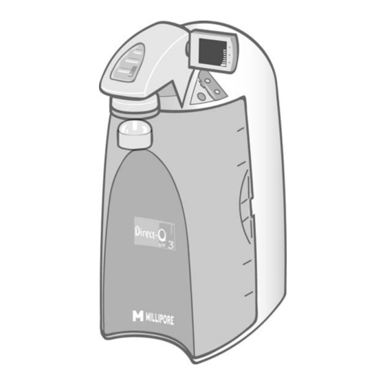
RODUCT NFORMATION Chapter 2 P RODUCT NFORMATION 2-1 D -Q S IRECT YSTEM VERVIEW DISPLAY The DISPLAY is used to monitor the water quality and system status. DISPENSING KEYPAD BUTTON The DISPENSING The KEYPAD is used to BUTTON is used to get access operating functions and Product Water. -
Page 12: Schematic Of Main Components
RODUCT NFORMATION 2-3 S CHEMATIC OF OMPONENTS Booster Pump 6 Litre Tank Inlet Solenoid Valve Distribution Pump SmartPak DQ3 UV Lamp 185 nm (UV System) (Pretreatment and RO Cartridge) SmartPak DQ3 RO Reject Solenoid Valve (Ion Exchange Polisher Cartridge) RO Reject Capillary Product Resistivity Cell Check Valve Point-of-Use (POU) Solenoid Valve... -
Page 13: Technical
RODUCT NFORMATION 2-5 T ECHNICAL PECIFICATIONS IMENSIONS YSTEM EIGHT IDTH AND EPTH 54 cm 14.9 cm 29.0 cm 42 cm HIPPING ♦ Height: 56 cm ♦ Width: 42 cm ♦ Depth: 64 cm EIGHT SYSTEM Direct-Q 3 Direct-Q 3 UV Operating Weight 17.6 kg 18.2 kg... -
Page 14: Chapter 3 Pre Installation
NSTALLATION Chapter 3 P NSTALLATION 3-1 I NSTALLATION EQUIREMENTS EEDWATER EQUIREMENTS Type of Feedwater Potable ≥ 40 LPH Flowrate ≥ 0.5 bar Minimum Pressure ≤ 6 bar Maximum Pressure < 2000 μS/cm Conductivity 5 to 35 °C Temperature 4 - 10 Fouling Index <... -
Page 15: Environmental Requirements
30 Litres can be used instead of the internal 6 Litre tank. The Tank Connector Kit is used to connect the 30 L tank to the system. The mounting hardware for connecting the external tank to the system is not included and must be supplied. The Millipore Catalogue Number for the 30 L PE Reservoir is TANKPE030. - 7 -... -
Page 16: Unpacking The Direct -Q − What ' S Inside
It is highly suggested to become familiar with the items that are shipped since these will be used in the Installation section of this manual. Contact Millipore if an item is missing. - 8 -... -
Page 17: Chapter 4 Installation
NSTALLATION Chapter 4 I NSTALLATION 4-1 P REPARATION OF THE YSTEM Open the front cover. Locate the tie wrap used to hold the Booster Pump in place during shipping (A). Press on the tab of the tie wrap (B). Remove and pull the tie wrap out. Locate the protective foam found at the UV lamp cable. -
Page 18: Connection Of Tubing
NSTALLATION 4-2 C ONNECTION OF UBING Rotate the Direct-Q so you can see the back of the system (see photo A). FEEDWATER OVERFLOW TUBING TUBING 2. REJECT 4. TANK TUBING OUTLET EEDWATER UBING Locate the Feedwater Tubing exiting from the bottom middle of the system (B). A 1/2 inch Female GAZ fitting with a screen filter is attached at the end of this tubing. -
Page 19: Reject Tubing
NSTALLATION EJECT UBING Locate the Reject Tubing exiting from the bottom middle of the system (D). Unroll it. Secure the tubing into a sink or drain. REJECT TUBING VERFLOW UBING Locate the Overflow Tubing exiting from the bottom right of the system (E). Unroll it. Secure the tubing into a sink or drain. -
Page 20: Tank Outlet Tubing
NSTALLATION UTLET UBING Locate the Tank Outlet Valve, the Tank Outlet Tubing and the adaptor fitting in the Accessories Bag. Install the Tank Outlet Valve and Tubing as shown (F, G, and H). Open the Tank Outlet Valve (I). This allows the tank to be emptied of any water in it. -
Page 21: Connection Of The Power Cord − Turning On The System Power
NSTALLATION − T 4-3 C ONNECTION OF THE OWER URNING ON THE YSTEM OWER Open the front cover of the system (A). This will allow the system to go into STANDBY mode once the system is powered. Plug the Power Cord into the system (B). Plug the other end of the Power Cord into an appropriate source of electrical power (i.e. -
Page 22: Installation Of The
NSTALLATION 4-4 I NSTALLATION OF THE MART Open the Tank Outlet Valve before installing a new SmartPak. This keeps the tank from filling ATTENTION until the SmartPak is rinsed out (A). Do not touch the UV Lamp when replacing the SmartPak. - Page 23 NSTALLATION Install the SmartPak until it is fully seated into the system ports as shown (D, E and F). Close the front cover. NOTE: The Tank Outlet Valve should be left open (G). - 15 -...
-
Page 24: Flush Mode
NSTALLATION LUSH The Tank Outlet Valve should be left open during FLUSH mode. ATTENTION The system will now go into FLUSH mode for 15 minutes (H). This is done to empty the SmartPak of air and hydrate the material inside. When FLUSH mode is finished, the system will go into FILLING TANK mode automatically (I). -
Page 25: Installation Of The Vent Filter
NSTALLATION 4-5 I NSTALLATION OF THE ILTER Obtain the Vent Filter. Insert the Vent Filter firmly into the port (A, B). 4-6 I NSTALLATION OF THE YGON UBING Locate the clear Tygon Tubing and the Barbed Fitting from the Accessories Bag. Screw the Barbed Fitting onto the bottom end of the POU Dispenser (C). -
Page 26: Purging Air From The System
NSTALLATION 4-7 P URGING IR FROM THE YSTEM At this time you should have installed the SmartPak, Barbed Fitting and the Tygon Tubing. Air trapped in the SmartPak should now be purged from the system. Verify that you have a full tank of RO water by viewing the Tank Level display (A). -
Page 27: Installation And
NSTALLATION 4-9 I NSTALLATION AND INSING OF THE INAL ILTER Obtain a Final Filter. It can be the Millipak Express 20 or the BioPak Ultrafiltration Cartridge. Remove the Tygon Tubing and the Barbed Fitting from the POU Dispenser. Screw the Final Filter onto the end of the POU Dispenser. The Final Filter should be turned until it is hand tight (A). -
Page 28: How To Calibrate The Flowrate From The Direct -Q (F02)
NSTALLATION 4-10 H OW TO ALIBRATE THE LOWRATE FROM THE IRECT (F02) Before calibrating the Product flowrate from the Direct-Q, you will need a 1 Litre graduated cylinder to measure the total volume of water that will be dispensed. The Final Filter should be installed. - Page 29 NSTALLATION Measure the total volume of water (in Litres) dispensed from the system using a 1 L graduated cylinder. Press the “+” or “-“ Button to match the volume Display to the volume measured. To exit the menu, press and hold the Main Button 2 seconds.
-
Page 30: How To Show Resistivity Or Conductivity Units (C01)
NSTALLATION 4-11 H (C01) OW TO ESISTIVITY OR ONDUCTIVITY NITS EMPERATURE OMPENSATED OR NON EMPERATURE OMPENSATED VALUES Temperature compensation is a way of ‘standardizing’ Resistivity or Conductivity to measurements that would be seen if the water temperature was 25 °C. Press the Main and “+“... - Page 31 NSTALLATION Press the “+” or “-“ Button to select Non Temperature Compensated Conductivity Units: μS/cm. To exit the menu, press and hold the Main Button for 2 seconds. To display the next menu option, press the Main Button once. - 23 -...
-
Page 32: How To Set The Resistivity Setpoint (C02)
NSTALLATION 4-12 H (C02) OW TO ET THE ESISTIVITY ETPOINT The Resistivity Setpoint is used to inform you when the Product resistivity is low. When the resistivity is below the setpoint, the Resistivity display will flash and the red Pack Alarm will be blinking (see Section 5-7 How to Understand Direct-Q Messages). - Page 33 NSTALLATION To exit the menu, press and hold the Main Button for 2 seconds. To display the next menu option, press the Main Button once. - 25 -...
-
Page 34: Sing The Direct -Q
SING THE IRECT Chapter 5 U SING THE IRECT 5-1 U NDERSTANDING THE ISPLAY The Display is used to view information about the Operating Modes, the Operating Parameters, Maintenance or Alarm messages and the Tank Level. Operating Modes 100 % TANK FULL Operating Tank... -
Page 35: Ro Water Using The Tank Outlet Valve
SING THE IRECT RO W ATER SING THE UTLET ALVE RO Water is obtained from the Tank Outlet. Open the Tank Outlet Valve when RO Water is needed. TANK OUTLET VALVE - 27 -... -
Page 36: How To Dispense An Exact Amount Of Product Water (F01)
SING THE IRECT (F01) OW TO ISPENSE AN XACT MOUNT OF RODUCT ATER Press the Main and “-“ Buttons together to enter the menu. The Display will show F01. Press the “+” or “-“ Button to adjust the exact amount of Product Water (in Litres) needed. - Page 37 SING THE IRECT To exit the menu, press and hold the Main Button for 2 seconds. To display the next menu option, press the Main Button once. - 29 -...
-
Page 38: Operating Modes
SING THE IRECT 5-3 O PERATING ODES TANDBY STANDBY mode is displayed when the front cover is removed. The system will depressurize during which STANDBY will be blinking on the Display for 10 seconds. All system operations are disabled. STANDBY mode is selected before attempting maintenance on the system. -
Page 39: Filling Tank
SING THE IRECT ILLING FILLING TANK mode is displayed when the tank is being filled with RO water until the 100% Tank Level display. FILLING TANK mode is launched automatically when the Tank Level display is below the 60% level or after a FLUSH cycle has been completed. -
Page 40: Dispensing
SING THE IRECT ISPENSING DISPENSING mode is displayed when Product Water is being dispensed. DISPENSING mode occurs because the Dispensing Button was pressed down. The Distribution Pump turns on. The resistivity and temperature of the Product Water is displayed during dispensing. The resistivity and temperature remain displayed for up to 10 seconds after dispensing is stopped. -
Page 41: How To View The
SING THE IRECT 5-4 H OW TO VIEW THE RODUCT ESISTIVITY AND EMPERATURE ILLING ANK MODE OR IN PERATE MODE The Display will show the last Product resistivity and temperature Press: values measured during DISPENSING mode during RECIRCULATION. The values are displayed for 5 seconds. NOTE: The Product resistivity and temperature are displayed automatically during DISPENSING mode or during RECIRCULATION. -
Page 42: How To Recirculate Water Manually Before Dispensing
SING THE IRECT 5-6 H OW TO RECIRCULATE WATER MANUALLY BEFORE DISPENSING This option is used to enhance the quality of the Product Water before dispensing water. The Distribution Pump will turn on and water will recirculate for up to 3 minutes. An auto-recirculation occurs for 3 minutes every 2 hours. -
Page 43: How To Understand Direct -Qmessages
When the red UV Lamp Alarm is displayed as a steady icon, the UV Lamp is not installed correctly or not installed at all. If the UV Lamp has been reinstalled and the Alarm is still displayed, then contact Millipore. - 35 -... -
Page 44: Flush: Open Tank Outlet Valve
SING THE IRECT LUSH UTLET ALVE Before FLUSH mode starts, the tank has to be emptied of water. The FLU counter display will be blinking if the system has detected that there is water in the tank. The Tank Outlet Valve must be opened. The system will automatically resume FLUSH mode when the tank is emptied of water. -
Page 45: Chapter 6 Maintenance
AINTENANCE Chapter 6 M AINTENANCE 6-1 M AINTENANCE CHEDULE WHAT TO DO WHEN? HOW TO? When Pack Alarm display is blinking. SmartPak See Section 6-2. Replacement When the system resistivity display is blinking. After a system or tank sanitization. Final Filter The Final Filter is replaced when the SmartPak is See Section 6-3. -
Page 46: How To Replace The Smart Pak
AINTENANCE 6-2 H OW TO EPLACE THE MART Open the Tank Outlet Valve before installing a new SmartPak. This keeps the tank from filling ATTENTION until the SmartPak is rinsed out (A). Do not touch the UV Lamp when replacing the SmartPak. -
Page 47: Installation
AINTENANCE NSTALLATION Remove the new SmartPak from its shipping box. Remove the protective caps on the ports of the SmartPak. Locate the O-rings on the ports. Wet them with water. It is preferable to wet them with ultrapure water. Install the SmartPak until it is fully seated into the system ports as shown (D, E and F). -
Page 48: Flush Mode
AINTENANCE LUSH The Tank Outlet Valve should be left open during FLUSH mode. ATTENTION The system will now go into FLUSH mode for 15 minutes (H). This is done to empty the SmartPak of air and hydrate the material inside. When FLUSH mode is finished, the system will go into FILLING TANK mode automatically (I). -
Page 49: Replacing The Vent Filter
AINTENANCE EPLACING THE ILTER The Vent Filter should be replaced whenever the SmartPak is replaced. Remove the Vent Filter (L). Insert the new Vent Filter into the fitting. See Section 4-5 Installation of the Vent Filter. NSTALLING THE YGON UBING Install the Barbed Fitting and Tygon Tubing (M). -
Page 50: Eplace The Final Filter
AINTENANCE 6-3 H OW TO EPLACE THE INAL ILTER The Final Filter is normally replaced when the SmartPak is replaced or at an earlier time if it becomes clogged. A clogged Final Filter can reduce the Product Water flowrate. Make sure the SmartPak has been hydrated ATTENTION overnight. -
Page 51: How To Clean The Screen Filter
AINTENANCE 6-4 H OW TO LEAN THE CREEN ILTER The purpose of the Screen Filter is to prevent large particles or other debris from entering the system. If the Screen Filter becomes blocked with debris, then the Feedwater will not flow freely to the system. It is recommended to clean the Screen Filter twice a year or whenever it may have become clogged. -
Page 52: How To Calibrate The Tank Level (C04)
AINTENANCE 6-5 H (C04) OW TO ALIBRATE THE EVEL Before calibrating the tank level, the tank needs to be filled to the 100% level or TANK FULL. Press the Main and “+“ Buttons together to enter the menu. The Display will show C01. - Page 53 AINTENANCE Open the Tank Outlet Valve. Allow the tank to be emptied to its lowest water level. NOTE: The lowest water level is not calibrated if the amount of water emptied from the tank is less than 10%. Close the Tank Outlet Valve.
-
Page 54: How To Empty The Tank (C03)
AINTENANCE 6-6 H (C03) OW TO MPTY THE The tank can be fully emptied of water through the POU Dispenser. This option is used when performing a system sanitization. Before emptying the tank, it is recommended to remove the Final Filter and to install the Barbed Fitting and Tygon Tubing. - Page 55 AINTENANCE When the system has finished emptying the tank, the system will start FILLINK TANK mode automatically. - 47 -...
-
Page 56: How To Sanitize The System
Locate the clear elbow fitting, the clear tubing and the syringe in the Sanitization Kit (B). You will need 200 ml of 30% Hydrogen Peroxide solution and 200 ml of purified water. Millipore does not sell Hydrogen Peroxide but it is readily available through most Scientific Supply Companies. -
Page 57: Sanitizing The System And The Tank
AINTENANCE ANITIZING THE YSTEM AND THE Open the front cover to let the system go into STANDBY mode (C). Remove the Vent Filter and install the clear elbow fitting from the Sanitization Kit (D). Introduce the male connector of the clear tubing firmly into the elbow fitting (E). Inject 200 ml (1 ml = 1 cc) of Hydrogen Peroxide solution (30%) into the 6 Litre tank via the clear tubing (F). - Page 58 AINTENANCE - 50 -...
- Page 59 AINTENANCE Let the system stand for 1 hour for effective bacteria elimination. (After 1 hour) Remove the Final Filter. Install the Barbed Fitting and Tygon Tubing (I). Perform an EMPTY TANK (C03) to dispense all the water in the tank (J). Once the tank is empty, the system will now go into FILLING TANK mode.
- Page 60 AINTENANCE - 52 -...
-
Page 61: Ow To Anitize The Ank Only
Locate the clear elbow fitting, the clear tubing and the syringe in the Sanitization Kit (B). You will need 200 ml of 30% Hydrogen Peroxide solution and 200 ml of purified water. Millipore does not sell Hydrogen Peroxide but it is readily available through most Scientific Supply Companies. -
Page 62: Sanitizing The Tank
AINTENANCE ANITIZING THE Open the front cover to go into STANDBY mode (C). Remove the Vent Filter and install the clear elbow fitting from the Sanitization Kit (D). Introduce the male connector of the clear tubing firmly into the elbow fitting (E). Inject 200 ml (1 ml = 1 cc) of Hydrogen Peroxide solution (30%) into the 6 Litre tank via the clear tubing (F). - Page 63 AINTENANCE - 55 -...
- Page 64 AINTENANCE When the tank is full, open the front cover to go into STANDBY mode (I). Let the system stand for 1 hour for effective bacteria elimination. (After 1 hour) Check that the Tank Outlet Tubing is secured into the drain. Open the Tank Outlet Valve to drain all the water from the tank (J).
-
Page 65: How To Replace The Uv Lamp
AINTENANCE 6-9 H UV L (UV S OW TO EPLACE THE YSTEM ONLY The red UV Lamp Alarm will be blinking on the Display when it is time to exchange the UV Lamp. The message is shown when the UV Timer has reached 0 days (see Section 6-10 How to Reset the UV Lamp Timer). -
Page 66: Removing The Uv Lamp
AINTENANCE UV L EMOVING THE ® Detach the Velcro belt of the UV housing. Pull the UV housing out so that the UV Lamp cable is accessible (D). NOTE: Use the gloves supplied with the UV replacement kit. Pull the UV Lamp out of the UV housing by its electrical cable (E). Unplug the electrical cable from the UV Lamp (F). -
Page 67: Installing The New Uv Lamp
AINTENANCE UV L NSTALLING THE NEW Ensure that you use the gloves supplied with the UV replacement kit. Plug the electrical cable to the new UV Lamp (G). Carefully insert the UV Lamp into the UV housing (H). Attach the UV housing with the Velcro belt (I). Install the SmartPak (J). -
Page 68: How To View Or Reset The Uv Lamp Timer (C05)
AINTENANCE 6-10 H UV L (C05) OW TO IEW OR ESET THE IMER The UV Lamp Timer should be reset only after the UV Lamp has been replaced (see Section 6-9 How to Replace the UV Lamp). The UV Lamp Timer displays the time left until the UV Lamp needs to be replaced. The Display will show the red UV Lamp Alarm icon blinking when the Timer reaches 0 days. -
Page 69: How To Reset The Uv Lamp Timer
AINTENANCE UV L OW TO ESET THE IMER Press the Main and “+“ Buttons together to enter the menu. The Display will show C01. Press the Main Button 4 times. The Display will show C05 and “0” days left on the UV Timer. -
Page 70: Chapter 7 Troubleshooting
The Display screen is blank. No source of electrical Check source power. electrical power. Main Power Fuse is blown. Contact Millipore. The Tank Outlet Valve is Close Tank Outlet open. The water in the tank Valve. is diverted into the drain. - Page 71 SmartPak. The Product resistivity is less than the Resistivity Setpoint set in menu option C02. SmartPak Reinstall the SmartPak. installed correctly or not If the red Pack Alarm is still installed at all. displayed, then contact Millipore. - 63 -...
- Page 72 UV System only The UV Lamp is not Power OFF the system and installed correctly or not reinstall the UV Lamp. installed at all. If the red UV Lamp Alarm still displayed, then contact Millipore. UV System only - 64 -...
-
Page 73: Chapter 8 Ordering Information
Chapter 8 O RDERING NFORMATION 8-1 C -Q S ATALOGUE UMBERS FOR IRECT YSTEMS For 230 VAC, 120 VAC, 100 VAC: 0 = D -Q 3 IRECT V = D -Q 3 UV IRECT 8-2 C ATALOGUE UMBERS FOR ONSUMABLES Consumable Item Catalogue Number SmartPak DQ3...
Need help?
Do you have a question about the DIRECT-Q 3 SYSTEM and is the answer not in the manual?
Questions and answers
hello i am having trouble with the M direct Q3 it is stuck on flu 15 mode and is not doing anything