Table of Contents
Advertisement
Quick Links
Advertisement
Table of Contents

Subscribe to Our Youtube Channel
Related Manuals for Sony AC-DN2B


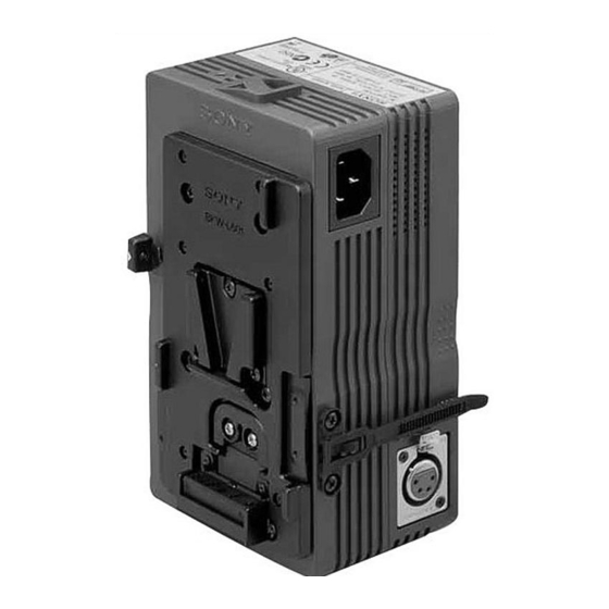
Summary of Contents for Sony AC-DN2B
- Page 1 AC ADAPTOR AC-DN2B MAINTENANCE MANUAL 1st Edition Serial No. 10001 and Higher...
- Page 2 Ce manual est destiné uniquement aux personnes compétentes en charge de l’entretien. Afin de réduire les risques de décharge électrique, d’incendie ou de blessure n’effectuer que les réparations indiquées dans le mode d’emploi à moins d’être qualifié pour en effectuer d’autres. Pour toute réparation faire appel à une personne compétente uniquement. AC-DN2B...
-
Page 3: Table Of Contents
Output Voltage Adjustment ..............2-1 (E) 2-3. Note after Adjustment ................2-1 (E) 3. Spare Parts 3-1. Exploded Views ..................3-1 3-2. Electrical Parts List ..................3-3 3-3. Supplied Accessory ..................3-4 3-4. Optional Fixture ..................3-4 1 (E) AC-DN2B... - Page 4 4. Diagrams and Board Layouts Overall ........................4-1 MAIN ........................4-2 SUB01 ........................4-3 SUB02 ........................4-3 Frame ........................4-4 2 (E) AC-DN2B...
-
Page 5: Manual Structure
Manual Structure Purpose of this manual This manual is the maintenance manual for AC Adaptor AC-DN2B. This manual describes the information items on maintenance, and items that premise the service based on the components parts such as alignment, schematic diagram, board layout and spare parts list, assuming use of service engineers. -
Page 7: Service Overview
When connecting a cable to the DC OUT connector (XLR, power code for your location. 4P), be sure to use the specified connector/complete cable assemblies. SONY POWER CORD (2.4 m) DK-2401L (Angle type) Fig. Power cord Rated current Rated voltage... -
Page 8: Connector Input/Output Signals
DC OUT (3P) _ _ _ _ _ EXT VIEW _ _ _ _ _ Pin No. Signal Specifications BATT (_) OUT GND for DC OUT BATT (+) OUT +16.5 to +16.9 V, 2.2 A MAX RID IN SENS 1-2 (E) AC-DN2B... -
Page 9: Removing The Cabinets
2. Remove the four screws (PSW3 x 8) and remove the upper case. 3. Remove the two screws (B3 x 6) securing the shield plate. PSW3 x 8 PSW3 x 8 Upper case Shield plate B3 x 6 1-3 (E) AC-DN2B... -
Page 10: Replacing The Fuse
Sony P/N : 1-763-098-11 Sony P/N : ! 9-885-009-46 5 A 250 V Recommended Replacement Period : Every five years 1. Remove the cabinets while referring to Section 1-4. -
Page 11: Notes On Repair Parts
Therefore, specified parts should be used in the case of replacement. 2. Standardization of Parts Some repair parts supplied by Sony differ from those used for the unit. These are because of parts common- ality and improvement. Parts list has the present standardized repair parts. -
Page 13: Electrical Alignment
Specifications : 16.7 ± 0.3 V Connection <Connection for 5P terminal> Lower cover Electric Load VR251 DC Voltmeter SUB02 board (B side) 2-3. Note after Adjustment After adjustment has been completed, be sure to lock 1VR251 with paint. 2-1 (E) AC-DN2B... -
Page 15: Spare Parts
7-627-556-77 s SCREW PRECISION +P2.6X6 TYPE1 9-885-004-70 o HARNESS ASSY, INLET(WITH SW) 7-682-547-09 s SCREW +B3X6 9-885-009-68 o CASE, UPPER 7-684-221-00 s NUT 4, HEXAGON CAP 9-885-009-69 o HARNESS ASSY, OUTPUT 7-685-752-09 s SCREW +PTT3X8 7-685-792-09 s SCREW +PTP2.6X6 AC-DN2B... - Page 16 7-627-553-38 s SCREW, PRECISION +P 2X3 3-669-596-00 s WASHER (2.3), STOPPER 7-627-556-38 s SCREW +P 2.6X4.0 3-679-648-02 o SPRING, COMPRESSION 7-682-546-09 s SCREW +B 3X5 3-679-688-02 o LEVER, RELEASE 7-682-948-01 s SCREW +PSW 3X8 3-679-690-02 o MOUNT, V 3-680-952-01 o KNOB, RELEASE LEVER AC-DN2B...
-
Page 17: Electrical Parts List
9-885-009-09 s DIODE 1SS184-TE85L 9-885-009-09 s DIODE 1SS184-TE85L 9-885-009-09 s DIODE 1SS184-TE85L 9-885-009-09 s DIODE 1SS184-TE85L 9-885-009-09 s DIODE 1SS184-TE85L 9-885-009-09 s DIODE 1SS184-TE85L 9-885-009-09 s DIODE 1SS184-TE85L 9-885-009-09 s DIODE 1SS184-TE85L 9-885-009-10 s DIODE U2JC44 9-885-009-11 s DIODE FCH30A06 AC-DN2B... -
Page 18: Supplied Accessory
9-885-009-67 s DIODE TLG223 ----- FRAME ----- Ref.No. or Q’ty Part No. SP Description HN001 9-885-009-69 o HARNESS ASSY, OUTPUT HN002 ! 9-885-009-70 o HARNESS ASSY, INLET (WITH SW) HN003 9-885-009-74 o CONNECTOR ASSY, BATTERY HN004 9-885-009-75 o HARNESS ASSY, XLR AC-DN2B... -
Page 19: Diagrams And Board Layouts
Overall Overall Section 4 Diagrams and Board Layouts AC-DN2B (SY) : S/N 10001 and Higher MAIN Overall LOT NO. 085- AC-DN2B... -
Page 20: Main
MAIN MAIN AC-DN2B (SY) : S/N 10001 and Higher MAIN MAIN -A SIDE- -B SIDE- AC-DN2B... -
Page 21: Sub01
SUB01, SUB02 SUB01, SUB02 AC-DN2B (SY) : S/N 10001 and Higher SUB01 SUB01 -A SIDE- -B SIDE- AC-DN2B (SY) : S/N 10001 and Higher SUB02 SUB02 -A SIDE- -B SIDE- AC-DN2B... -
Page 22: Frame
Frame Frame AC-DN2B (SY) : S/N 10001 and Higher CN52 HN004 DC OUT AC(H)IN ZD01 AC(C)IN HN002 CN51 HN003 DC OUT ZD02 C109 D251 CN252 HN001 RID IN R108 C108 R122 R251 C102 BATT(+)OUT R109 SENS BATT(-)OUT R253 C101 R257... - Page 23 2 V AC range are suitable. (See Fig. A) To Exposed Metal Parts on Set 0.15 µ F 1.5 k Z voltmeter (0.75V) Earth Ground Fig A. Using an AC voltmeter to check AC leakage. AC-DN2B...
- Page 24 Printed in Japan Sony Corporation AC-DN2B (SY) J, E 2000. 10 16 Communication System Solutions Network Company 9-968-578-01 (1) ©2000...
Need help?
Do you have a question about the AC-DN2B and is the answer not in the manual?
Questions and answers