Table of Contents
Advertisement
Quick Links
Advertisement
Table of Contents

Subscribe to Our Youtube Channel
Related Manuals for Sharkoon T9


Summary of Contents for Sharkoon T9
- Page 1 Manual...
-
Page 2: Table Of Contents
10. The pre-installed fans (Value edition only) Installation of additional fans / optimized airflow Dear customer! Congratulations for purchasing this premium quality SHARKOON product. For a long life time and to take full advantage of this product we recommend you to read this manual completely. -
Page 3: Features
475 x 200 x 440 mm (L x W x H) • Weight: ~6.6 kg 2. Package content • PC case “T9 Value” or "T9 Economy" • Screw kit: Screws for mainboard Screws for PSU moun- Screws for drive moun-... - Page 4 Mounting angles for HDDs (decoupled / A) and 3.5" devices (not decoupled / B) Quick fasteners for optical drives 5.25" bezel with 3.5" opening Note: If you are missing any of the items listed above, please contact our customer service immediately: support@sharkoon.com (Germany and Europe) support@sharkoon.com.tw (international).
-
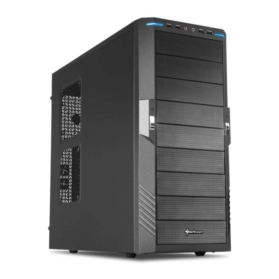
Page 5: The Case At A Glance
C – 5.25" drive bays D – covered: pre-installed 120 mm fans (Value edition) Side view (closed/left) A – T9 Economy edition a – Brackets for two 120 mm fans B – T9 Value edition b – Acrylic side panel... - Page 6 Side view (opened/left) A – Drive bays for 5.25" devices B – Mainboard mounting panel with: a – Installation opening coolers and b – Cable management system Back side view A – Opening for I/O shield B – Pre-installed 120 mm fan (Value edition) C –...
-
Page 7: Installation Of A Mainboard
4. Installation of a mainboard 1. Open the case by loosening the thumb screws on the case’s back side and removing the left side panel. Lay down the case sidewise on an even surface. 2. The mainboard’s mounting panel inside the case provides various drillings to fix the stand-offs (fig. - Page 8 3. Remove the mainboard and screw the stand-offs into the respective drillings of the mounting panel (fig. 3). (Stand-offs) fig. 3 4. Press the I/O shield (delivered with the mainboard) into the I/O shield opening in the case’s back side. 5.
-
Page 9: Installation Of A Psu
6. Plug the connectors of the case’s front bezel to the respective connectors of the mainboard (also refer to your mainboard’s manual for further information). Note: The eSATA cable connected to the front eSATA connection should not exceed 50 cm of length otherwise transmission errors may occur! With premium quality eSATA cables this maximum length may be exceeded. -
Page 10: Installation Of A Hdd
6. Installation of a HDD 1. Remove the case’s right side panel. 2. Attach the decoupled mounting angles to the HDD from both sides (fig. 7). (Screws for HDD mounting) (Decoupled mounting angles) fig. 7 3. Slide the HDD with attached mounting angles into the case’s respective drive bay and screw it from both sides (fig. -
Page 11: Installation Of An Optical Device
7. Installation of an optical device 1. Remove the case’s front panel by gently dragging it towards you (fig. 9). fig. 9 2. Dismantle the 5.25" front bezel from the mounting bay in which you intend to install the drive by loosening its screws and pushing the bezel to the inside (fig. 10). Remove the quick fasteners (fig. -
Page 12: Installation Of A 3.5" Device
4. Attach the optical device from both sides using the quick fasteners (fig. 13). fig. 13 Note: If you intend to transport the case we recommend securing (additionally) the installed drives: Screws for 5.25" drive mounting 5. Connect the optical drive to the power supply and the mainboard. (Put the front bezel back onto the case.) 8. - Page 13 3. Screw the mounting angles to the 3.5" device from both sides (fig. 16). fig. 16 4. Slide the 3.5" device with attached mounting rails into the case’s drive bay (fig. 17) and screw it to the drive bay from both sides (fig. 18). fig.
-
Page 14: Installation Of An Add-On Card
9. Installation of an add-on card 1. Remove the slot bezel’s fixation screw and take away the slot bezel (fig. 20). fig. 20 2. Insert the add-on card into the mainboard’s respective slot and fix it to the case by re-attaching the fixation screw (fig. -
Page 15: Installation Of Additional Fans / Optimized Airflow
Legal disclaimer: As a continuing policy of product improvement at SHARKOON, the design and specifications are subject to change without prior notice. National product specifications may vary. All rights reserved especially (also in extracts) for translation, reprinting, reproduction by copying or other technical means.
Need help?
Do you have a question about the T9 and is the answer not in the manual?
Questions and answers