
Related Manuals for Sharkoon TAREA


Summary of Contents for Sharkoon TAREA
- Page 1 Handbuch Manual Manuel d‘utilisation Guia usario Manuale d´istruzioni Gebruiksaanwijzing Guia usário Instukcja obstugi 使用手冊 ユー ザー マニ ュアル...
-
Page 2: Table Of Contents
Installation of an add-on card 10. Installation of additional fans / optimized airflow Dear customer! Congratulations for purchasing this premium quality SHARKOON product. For a long life time and to take full advantage of this product we recommend you to read this manual completely. -
Page 3: Features
1x 80 mm or 1x 120 mm fan (optional) • Dimensions: 475 x 202 x 440 mm (L x W x H) • Weight: ~6.2 kg 2. Package content • ATX case "Tarea" • Screw kit: Screws for mainboard Screws for PSU... - Page 4 Mounting angles for HDDs (with decoupling / A) and 3.5" devices (not decoupled / B) Quick fasteners for ODDs 5.25" bezel with 3.5" opening Note: If you are missing any of the items listed above, please contact our customer service immediately: support@sharkoon.com (Germany and Europe) support@sharkoon.com.tw (international). Tarea...
-
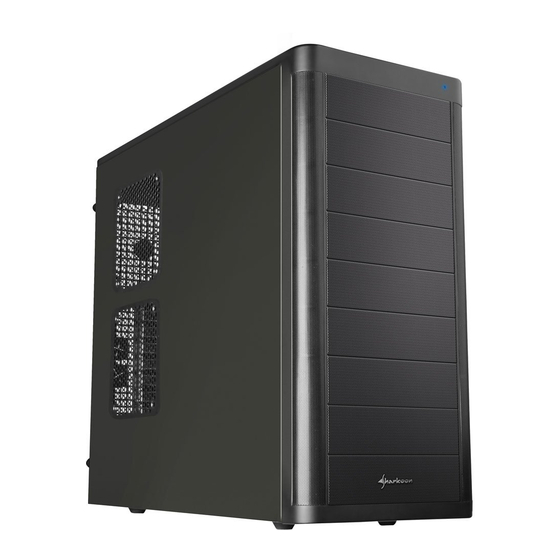
Page 5: The Case At A Glance
A – Power and B – Reset button Case top: C – Top I/O with: a – 1x headphone and microphone connector b – 2x USB2.0 and c – 1x eSATA connector Side view (closed/left) A – Fan brackets (2x 120 mm) Tarea... - Page 6 A – Opening for I/O shield B – 120 mm fan bracket C – Slot bezels D – Openings for water cooling E – PSU bracket F – Thumb screws Bottom view A – Case feet B – Air intake for PSU Tarea...
-
Page 7: Installation Of A Mainboard
Lay down the case sidewise on an even surface. 2. The mainboard’s mounting panel inside the case provides various drillings to fix the stand-offs (fig. 1). fig. 1 The mainboard contains special screw openings (fig. 2). fig. 2 Tarea... - Page 8 4. Press the I/O shield (delivered with the mainboard) into the I/O shield opening in the case’s back side. 5. Place the mainboard back onto the stand-offs and screw the mainboard to them (fig. 4). (Screws for mainboard mounting) fig. 4 Tarea...
-
Page 9: Installation Of A Psu
1. Set up the case in front of you and put the PSU from the inside against the PSU bracket on the case’s back side (fig. 5). fig. 5 2. Screw the PSU to the case from the outside (fig. 6). (Screws for PSU mounting) fig. 6 Tarea... -
Page 10: Installation Of A Hdd
(Decoupled mounting angles) fig. 7 3. Slide the HDD with attached mounting angles into the case’s respective drive bay and screw it from both sides (fig. 8). fig. 8 4. Connect the HDD to the power supply and the mainboard. Tarea... -
Page 11: Installation Of An Optical Device
(fig. 10). Remove the quick fasteners (fig. 11). fig. 10 fig. 11 (Carefully take out an optionally present metal bezel covering the 3.5" drive bay by using a gripper.) 3. Slide the optical drive into the case’s drive bay (fig. 12). fig. 12 Tarea... -
Page 12: Installation Of A 3.5" Device
(fig. 14). Remove the quick fasteners (fig. 15). fig. 14 fig. 15 (Carefully take out an optionally present metal bezel covering the drive bay by using a gripper.) Tarea... - Page 13 5. Connect the 3.5" device to the power supply and the mainboard. 6. Screw the 5.25" bezel with 3.5" opening into the front panel (fig. 19) and place it back onto the case. 5.25" bezel with 3.5" opening fig. 19 Tarea...
-
Page 14: Installation Of An Add-On Card
1. Remove the slot bezel’s fixation screw and take away the slot bezel (fig. 21). fig. 21 2. Insert the add-on card into the mainboard’s respective slot and fix it to the case by re-attaching the fixation screw (fig. 22). fig. 22 Tarea... -
Page 15: Installation Of Additional Fans / Optimized Airflow
Legal disclaimer: As a continuing policy of product improvement at SHARKOON, the design and specifications are subject to change without prior notice. National product specifications may vary. All rights reserved especially (also in extracts) for translation, reprinting, reproduction by copying or other technical means.
Need help?
Do you have a question about the TAREA and is the answer not in the manual?
Questions and answers