Table of Contents
Advertisement
Quick Links
Advertisement
Table of Contents

Subscribe to Our Youtube Channel
Related Manuals for Sharkoon MS120


Summary of Contents for Sharkoon MS120
- Page 1 Manual MS120...
-
Page 2: Table Of Contents
12. Installation of additional fans / optimized airflow Dear customer! Congratulations for purchasing this premium quality SHARKOON product. For a long life time and to take full advantage of this product we recommend you to read this manual completely. Enjoy our product! SHARKOON Technologies ... -
Page 3: Features
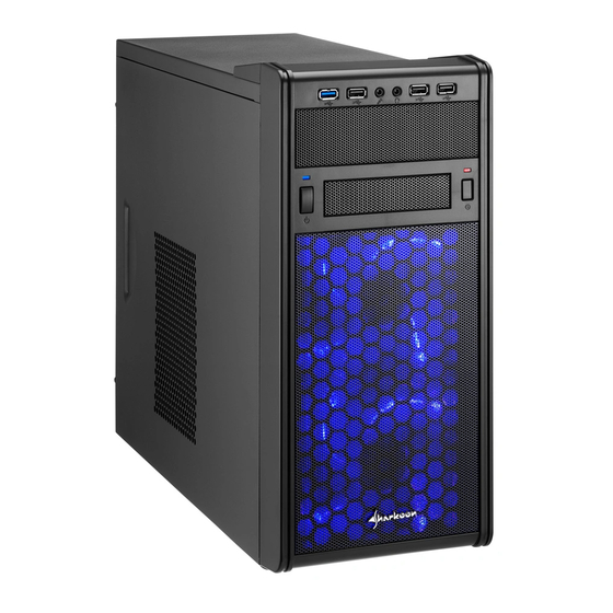
Dimensions: 420 x 175 x 375 mm (L x W x H) • Weight: ~4 kg • Fan configuration: Case front 2x 120 mm LED fans Rear panel 1x 80 mm or 1x 92 mm fan (optional) Case bottom 1x 120 mm fan (optional) MS120... -
Page 4: Package Content
2. Package contents • ATX case "MS120" • Screw kit: Screws for mainboard and Mounting screws for 2.5" Screws for PSU Screws for HDD mounting drive mounting HDDs/SSDs mounting (3.5" and 5.25") • Accessory kit: Stand-offs for mainboard Washers Cable tie (A) and speaker (B) -
Page 5: The Case At A Glance
C – Power LED D – On/off button E – 3.5" mounting bay F – LED for HDD activity G – Reset button H – behind the mesh panel: 2x 120 mm LED fans Side panel (closed/left) A – Air inlet MS120... - Page 6 D – Mainboard mounting panel Rear panel A – PSU bracket B – Opening for I/O shield C – Fan bracket (80 or 92 mm) D – Slot bezels E – Thumb screws F – Connection cable for the front USB3.0 plug MS120...
-
Page 7: Installation Notes
2. In order to install long VGA cards, it might be necessary to remove the left HDD mounting panel (see 5.). To have the option to install at least two 3.5" HDDs, there is an additional HDD attachment in the bottom panel of the case. MS120... -
Page 8: Removing The Left Hdd Mounting Plate
1. Unscrew the thumb screws on the back side of the case and remove both side panels. 2. Unscrew the three attachment screws of the HDD mounting panel and remove the panel from the case (fig. 2 a-c). Fig. 2 a-c MS120... -
Page 9: Installation Of A Mainboard
(fig. 3). Fig. 3 The mainboard contains special screw mounts (fig. 4). Fig. 4 Place the mainboard to the mounting panel. A standoff must be screwed into every hole on the mounting panel visible through the mainboard’s screw openings. MS120... - Page 10 4. Insert the I/O shield (delivered with the mainboard) into the I/O shield opening in the rear panel of the case. 5. Place the mainboard back onto the standoffs and screw the mainboard to them (fig. 6). (Screws for mainboard mounting) Fig. 6 MS120...
-
Page 11: Installation Of A Psu
1. Position the case in front of you and set the PSU from the inside against the PSU bracket on the case’s rear panel. 2. Screw the PSU to the case from the outside (fig. 7). (Screws for PSU mounting) Fig. 7 MS120... -
Page 12: Installation Of A Hdd
Prior to the 2.5" HDD/SSD installation, the buffers for 3.5" HDDs must be removed from the attachments. 1. Hold the HDD/SSD against the respective attachment (fig. 8 a and b). Fig. 8 a (3.5" HDD) Fig. 8 b (2.5" HDD) MS120... -
Page 13: Into The Bottom Panel
1. To use the HDD attachment in the bottom panel, the left HDD attachment panel must be removed from the case (see above 5.). 2. Remove four buffers from the HDD attachment panel, which you removed from the case, and insert them into the openings on the case‘s bottom panel (fig. 10). (Buffers) Fig. 10 MS120... -
Page 14: Installation Of An Optical Device
Fig. 11 a und b 4. Connect the HDD to the power supply and the mainboard. 9. Installation of an optical device 1. Remove the case’s front panel by gently pulling it towards you (fig. 12). Fig. 12 MS120... - Page 15 2. Dismantle the 5.25" front bezel from the mounting bay by pushing it out of the front panel (fig. 13). Fig. 13 3. Place the front panel back onto the case. 4. Slide the optical drive into the case’s drive bay (fig. 14). Fig. 14 MS120...
-
Page 16: Installation Of A 3.5" Device
1. Remove the case’s front panel by gently pulling it towards you. 2. Dismantle the 3.5" front bezel by pushing it out of the front panel (fig. 16). Fig. 16 3. Place the front panel back onto the case. MS120... -
Page 17: Installation Of An Add-On Card
Fig. 17 5. Connect the 3.5" device to the power supply and the mainboard. 11. Installation of an add-on card 1. Remove the anchor screw of the slot bezel and take it from the case (fig. 18). Fig. 18 MS120... -
Page 18: Installation Of Additional Fans / Optimized Airflow
The PC components with the highest heat development should be placed directly within the airflow. 2. The installation of the lower fan is an additional application for VGA cooling. The bottom PCI slot of the mainboard will be occupied when used. MS120... -
Page 19: Legal Disclaimer
Legal disclaimer: As a continuing policy of product improvement at SHARKOON, the design and specifications are subject to change without prior notice. National product specifications may vary. All rights reserved especially (also in extracts) for translation, reprinting, reproduction by copying or other technical means.
Need help?
Do you have a question about the MS120 and is the answer not in the manual?
Questions and answers