Table of Contents
Advertisement
For service questions, contact US Stove at 1-800-750-2723.
For sales inquiries, contact Sylvane at 1-800-934-9194 or visit www.sylvane.com.
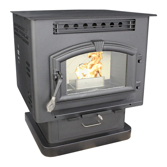
American Harvest
READ THIS ENTIRE MANUAL, THOROUGHLY, BEFORE ATTEMPTING TO INSTALL AND/
OR BURN YOUR NEW AMERICAN HARVEST *MULTI-FUEL HEATER. FAILURE TO FOLLOW
THESE INSTRUCTIONS MAY RESULT IN PROPERTY DAMAGE, BODILY INJURIES OR
Safety Notice: If this heater is not properly installed, a house fire may result.
For your safety, follow the installation directions. Contact local building or fire of-
ficials about restrictions and installation requirements peculiar to your area. Do
Not Plug this appliance into an electrical outlet before reading and understanding
all operations and always unplug the unit before attempting any work or main-
tenance. Do not connect this heater to any chimney flue already serving another
appliance. Carefully observe and maintain all clearances to combustibles.
A note about fuel: Use only dried shelled corn with a moisture content of 14%
or less (11 to 12% provides the best results); any pellet fuel used should
have an ash content of 1% or less. If not, efficiency will suffer. This heater has
successfully burned pellets with a 2-1/2% ash content, though less ash is preferred
and more efficient.
Your American Harvest Multi-Fuel Heater operates on a negative pressure. There-
fore, all venting connections (elbows, T-pipe) must be sealed and airtight.
*This heater is capable of burning wood, biomass pellets and a wide variety of grains,
UNITED STATES STOVE COMPANY GRANTS NO WARRANTY, IMPLIED OR STATED,
FOR THE INSTALLATION OR MAINTENANCE OF THE HEATER AND ASSUMES NO
United States Stove Company • 227 Industrial Park Road, P.O. Box 151 • South Pittsburg, TN 37380 • www.usstove.com
USSC
i Use Hi-Temp silicone at each joint or connection.
including corn, soybeans, cherry and olive pits, and all larger seeds.
SAVE THESE INSTRUCTIONS
RESPONSIBILITY FOR ANY CONSEQUENTIAL DAMAGE(S).
Tested &
Listed By
Safety Tested to ASTM-E 1509, (UM) 84-HUD
S
C
U
S
EVEN DEATH.
Portland
Oregon USA
US
Omni-Test Laboratories, Inc.
851772 rev A
1
Advertisement
Table of Contents

Related Manuals for US Stove Company American Harvest 6041


Summary of Contents for US Stove Company American Harvest 6041
- Page 1 Tested & Portland Listed By Oregon USA Omni-Test Laboratories, Inc. Safety Tested to ASTM-E 1509, (UM) 84-HUD United States Stove Company • 227 Industrial Park Road, P.O. Box 151 • South Pittsburg, TN 37380 • www.usstove.com 851772 rev A USSC...
-
Page 2: Specifications
Initial burn off may cause slight smoke and odor the first few hours of operation. Perform initial burn outside if possible SPECIFICATIONS United States Stove Company reserves the right to alter products, specifications and price without notice. Safety Tested & Listed to ASTM- E 1509, (UM) 84-HUD, by OMNI Test Laboratories, Inc., Portland,... - Page 3 6041TP PEDESTAL TRIM ASSEMBLY Assemble trim pieces as shown with the screws provided in the parts bag. After trim assembly, attach to the pedestal base at the location shown using the screws provided. 6041HF ASSEMBLY Assembly 1. Unpack unit and make sure all components are included; (4) Legs, and all hardware for installation.
- Page 4 6041I ASSEMBLY DISCONNECT THE POWER CORD BEFORE SERVICING THIS Heater For the following assemblies, we suggest locating the unit near it’s desired location. Depending on installation, you may want to connect the exhaust venting before installing the facade parts. Assembly - Facade (Surround) Remove contents from packaging and make sure you have all components: (2) Top Facade (a)
-
Page 5: Component Location
COMPONENT LOCATION USSC... -
Page 6: Safety Steps
SAFETY STEPS IMPORTANT: Proper installation of this heater is necessary for safe and efficient operation. In- stalling this product improperly may result in a house fire and personal injury. All applicable building codes for your location must be followed. In areas where building codes require additional steps to the installation of this product not included in this manual, the building codes will take precedent and must be followed. -
Page 7: Shelled Corn
BURNING SOLID FUELS continued... SHELLED CORN (Dry, preferably corn with 11- 12% moisture content) • Corn must contain less than 14% moisture content. Wet corn will rapidly deteriorate heater components, reduce efficiency and void all warranties. Purchase a moisture tester if in doubt. •... -
Page 8: Hearth Protection
CLEARANCES TO COMBUSTIBLES 6041(TP)(HF) The heater must be installed with the following minimum clearances to side and back wall combustible materials. NOTE: These are minimum clearances to combustible walls established by the testing lab. PARALLEL - A - Sidewall to Top Edge of Unit 8 in./203mm... - Page 9 CLEARANCES TO COMBUSTIBLES 6041I USSC...
-
Page 10: Guidelines For Exhaust Venting Systems Design
GUIDELINES FOR EXHAUST VENTING SYSTEMS DESIGN It is recommended that only an authorized installer install your multi-fuel heater, preferably an NFI certified specialist. The following installation guidelines must be followed to ensure conformity with both the safety listing of this heater and to local building codes. -
Page 11: Design Guidelines For Outside Combustion Air Connection
DESIGN GUIDELINES FOR OUTSIDE COMBUSTION AIR CONNECTION 1. For installations with horizontal through-the-wall exhaust, it is strongly recommended that the heater combustion air be connected to the outside. If the home is newer or has been tightly insulated, it is required to install outside combustion air. -
Page 12: Installation Configurations
INSTALLATION CONFIGURATIONS The Multifuel Heater Model 6041TP/6041HF may be installed as follows: 1) A freestanding unit The Multifuel Heater Model 6041I insert may be installed as follows: 1) In a pre-fab firebox (Factory Built) 2) In an existing masonry fireplace 3) As a build-in MOBILE HOME INSTALLATION REQUIREMENTS IN ADDITION TO THE STANDARD INSTALLATION INSTRUCTION, THE FOLLOWING... - Page 13 Note: Always check dimensions on unit before cutting hole in wall 3" PL Vent Termination Cap 3" PL Vent 90° Elbow 3" PL Vent (12" Long) A MINIMUM OF 3 VERTICAL FEET OF PIPE OUTSIDE THE HOME IS REQUIRED! COMBUSTION EXHAUST OUTLET 10 1/16 AIR INTAKE...
- Page 14 THROUGH THE WALL, VERTICAL PIPE INSTALLATION WITH TERMINATION CAP A MINIMUM OF 3 VERTICAL FEET OF PIPE OUTSIDE THE HOME IS REQUIRED! The Hearth Pad is not required under the unit if the floor is noncombustible but is required 6 inches (152mm) beyond the front of the unit and 6 inches (152mm) beyond each side of the door if the floor is a combustible floor.
- Page 15 DESIGN GUIDELINES FOR 6041I INSERT INSTALLATION A MINIMUM OF 3 VERTICAL FEET OF PIPE OUTSIDE THE HOME IS REQUIRED! INSTALLATION AS A BUILT-IN FIREPLACE A continuous sheet of non-combustible floor protection must be installed underneath the unit to prevent the possibil- ity of embers falling through to the combustible floor.
- Page 16 DESIGN GUIDELINES FOR 6041I INSERT INSTALLATION INSTALLATION INTO A MASONRY FIREPLACE When installing into a masonry fireplace, DO NOT remove any bricks or masonry, with the following exception: masonry or steel, including the damper plate, may be removed from the smoke shelf and adjacent damper frame, if necessary, to accommo- date a chimney liner.
-
Page 17: Cleaning The Glass
GLASS MAINTENANCE, REMOVAL AND REPLACEMENT Your Multi-Fuel Heater comes to you with the glass door installed in place, ready for use. The glass is surrounded on the edges with a gasket and seated in a glass channel. It is held in place with two (2) clips. REMOVAL OF BROKEN OR DAMAGED CERAMIC GLASS Open the door and then lift it off of the hinges. -
Page 18: Understanding The Control Board
UNDERSTANDING THE CONTROL BOARD CONTROL PANEL Turning the heater OFF/ON, as well as adjustments for the fuel feed rate and room fan speed are performed by pressing the appropriate button(s) on the control panel which is located on the lower left-hand side of your American Harvest heater. The insert model 6041I is located on the left facade. - Page 19 TO START A FIRE... • Never use gasoline, gasoline-type lantern fuel, kerosene, charcoal lighter fluid, or similar liquids to start or “freshen up” a fire in this heater. Keep all such liquids well away from the heater while it is in use. Using Wood Pellets: Ensure your display shows a “Pr”...
-
Page 20: Disposal Of Ashes
DISPOSAL OF ASHES Disposal of Ashes Ashes should be placed in a metal container with a tight fitting lid. The closed container of ashes should be placed on a noncombustible floor or on the ground, well away from all combustible materials, pending final disposal. If the ashes are disposed of by burial in soil or otherwise locally dispersed, they should be retained in the closed container until all cinders have been thoroughly cooled. -
Page 21: Automatic Safety Features
Weekly Maintenance • Shut down the heater as directed in the operating instructions. Allow the heater to cool to room temperature. Re- move the small clean-out slides in the lower corners of the firebox. Tap the sides of the burn chamber with a wooden stick. -
Page 22: Control Board Functions
CONTROL BOARD FUNCTIONS START-UP SEQUENCE OF EVENTS Once the control panel is turned on, a timer begins that will start, stop and continue operation of the Multi-fuel Heater as a preset temperature is achieved. COMPONENT OPERATION START OPERATION END Draft Fan Starts Immediately Will continue until shutdown. - Page 23 ERROR CODES and DISPLAY INDICATORS Error Error Possible Code Description Causes Err1 • Inadequate ventilation. The high limit temperature sensor • Room fan failure. has tripped. • Exhaust Blockage. • Electrical Open in the over temperature switch or wiring. Err2 •...
-
Page 24: Troubleshooting
TROUBLE SHOOTING i Disconnect the power supply before performing any maintenance! NOTE: Turning the heater to “OFF” does not disconnect the power to all of the electrical components of the heater. i Never try to repair or replace any part of the heater unless instructions for doing so are given in this manual. All other work should be done by a trained technician. -
Page 25: Wiring Diagram
WIRING DIAGRAM WIRING SCHEMATIC USSC... - Page 26 PARTS DIAGRAM - 6041TP USSC...
- Page 27 PARTS LIST - 6041TP Part No. Part No. Description Description Qty. Qty. Part No. Part No. Description Description Qty. Qty. 69529 Pedestal 891180 Auger Cover Gasket, 0.188 x 1.0 Flat FbrGlss. 25410 Pedestal Bottom 88120 0.25 ft 25451 Pedestal Back 80488 Drive Motor (Auger) 69478...
- Page 28 PARTS DIAGRAM - 6041I USSC...
- Page 29 PARTS LIST - 6041I Part No. Description Qty. Part No. Description Qty. 891373 Pad, Door Hinge (Threaded) 25580 Left Side-Rear Cabinet 69547 Weldment Sub-Base 25578 Back, Cabinet 25569 Bracket, Caster 25587 Wldmt., Facade Panel Rt-Side 891424 Caster, Plastic 89943 Knob, Cabinet Door 1/4-20 x 1-1/2 Hex Bolt 83412 25585...
-
Page 30: Parts Diagram/List
TOP VIEW SCALE 1 : 1 891138 Handle, Nickel USSC REAR VIEW-PERSPECTIVE SCALE 3 / 4 DESCRIPTION SCALE SIZE UNITED STATES STOVE COMPANY TOLERANCES HOLES .005" -.001" EXCEPT DECIMAL BLANK NUMBER DWN BY ESTABLISHED 1869 .XX = 0.03 XXX = 0.010... - Page 31 NOTE USSC...
-
Page 32: Part Description
When placing an order or for warranty claims, please provide the following informa- tion found on the Certification Plate located below the ash door. PART NUMBER PART DESCRIPTION MODEL NUMBER - 6041 / 6041TP / 6041HF / 6041I SERIAL NUMBER______________ 227 Industrial Park Road P.O. Box 151...